EP1393832B1 - Verfahren und Vorrichtung zum Induktivbiegen von Rohren - Google Patents
Verfahren und Vorrichtung zum Induktivbiegen von Rohren Download PDFInfo
- Publication number
- EP1393832B1 EP1393832B1 EP03090269A EP03090269A EP1393832B1 EP 1393832 B1 EP1393832 B1 EP 1393832B1 EP 03090269 A EP03090269 A EP 03090269A EP 03090269 A EP03090269 A EP 03090269A EP 1393832 B1 EP1393832 B1 EP 1393832B1
- Authority
- EP
- European Patent Office
- Prior art keywords
- bending
- plane
- pressure rollers
- pressure
- induction
- Prior art date
- Legal status (The legal status is an assumption and is not a legal conclusion. Google has not performed a legal analysis and makes no representation as to the accuracy of the status listed.)
- Expired - Lifetime
Links
- 238000000034 method Methods 0.000 title claims description 25
- 238000012998 induction bending Methods 0.000 title claims description 10
- 238000005452 bending Methods 0.000 claims abstract description 25
- 238000010438 heat treatment Methods 0.000 claims abstract description 6
- 238000006073 displacement reaction Methods 0.000 claims 1
- 230000002093 peripheral effect Effects 0.000 abstract description 2
- 230000001939 inductive effect Effects 0.000 description 4
- 230000015572 biosynthetic process Effects 0.000 description 2
- 206010010219 Compulsions Diseases 0.000 description 1
- 230000001419 dependent effect Effects 0.000 description 1
- 238000011161 development Methods 0.000 description 1
- 230000018109 developmental process Effects 0.000 description 1
- 230000000694 effects Effects 0.000 description 1
- 238000004519 manufacturing process Methods 0.000 description 1
- 238000010792 warming Methods 0.000 description 1
Images


Classifications
-
- B—PERFORMING OPERATIONS; TRANSPORTING
- B21—MECHANICAL METAL-WORKING WITHOUT ESSENTIALLY REMOVING MATERIAL; PUNCHING METAL
- B21D—WORKING OR PROCESSING OF SHEET METAL OR METAL TUBES, RODS OR PROFILES WITHOUT ESSENTIALLY REMOVING MATERIAL; PUNCHING METAL
- B21D7/00—Bending rods, profiles, or tubes
- B21D7/02—Bending rods, profiles, or tubes over a stationary forming member; by use of a swinging forming member or abutment
- B21D7/024—Bending rods, profiles, or tubes over a stationary forming member; by use of a swinging forming member or abutment by a swinging forming member
- B21D7/025—Bending rods, profiles, or tubes over a stationary forming member; by use of a swinging forming member or abutment by a swinging forming member and pulling or pushing the ends of the work
-
- B—PERFORMING OPERATIONS; TRANSPORTING
- B21—MECHANICAL METAL-WORKING WITHOUT ESSENTIALLY REMOVING MATERIAL; PUNCHING METAL
- B21D—WORKING OR PROCESSING OF SHEET METAL OR METAL TUBES, RODS OR PROFILES WITHOUT ESSENTIALLY REMOVING MATERIAL; PUNCHING METAL
- B21D9/00—Bending tubes using mandrels or the like
- B21D9/16—Auxiliary equipment, e.g. machines for filling tubes with sand
- B21D9/18—Auxiliary equipment, e.g. machines for filling tubes with sand for heating or cooling of bends
Definitions
- the invention relates to a method and an apparatus for the induction bending of pipes according to the Preamble of claim 1, or of claim 8.
- This proposed procedure is to be carried out by a system in which before or behind or in front of and behind the inductor in an adjustable distance from the pipe Scaffold at least four in their distance from each other by means of known hydraulic Servomotors of a hydraulic system via hydraulic elements infinitely adjustable Pressure rollers arranged in at least two mutually perpendicular planes are.
- JP 56026625 A a device for the induction bending of pipes is disclosed.
- a guide is arranged, consisting of a tube comprising the holding device with a plurality of distributed over the circumference arranged pressure rollers.
- the distance between two opposing pressure rollers corresponds to the actual outside diameter of the incoming pipe.
- the adjustable to a predetermined distance pressure rollers to prevent the ovalization of the bent pipe.
- two axially spaced apart pressure rollers are provided per set of rollers.
- the object of the invention is to specify a method and a device for the induction bending of pipes, with the reproducible the formation of an impermissible ovality in the bow area is avoided.
- each of the heating zone leaving arc section in one of the largest expected ovality selected level at least two Setting the circumference to the nominal outside diameter of the pipe bend, forcibly guided, wherein in the rearward extension of the plane the center of rotation of the Biegearmes cuts.
- the optimal positions to be set and distances of the rollers are each through previous calculation, eg B. determined by finite element method (FEM).
- FEM finite element method
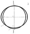
- Figure 2 shows the same cross section 2 of an arc section as Figure 1 but with an exaggerated representation of the wall thickness.
- the output tube is pressed not only oval by the forces acting on the induction bending, but at the same time the wall thickness is reduced 3 in the tension zone and the wall thickness 4 is upset in the pressure zone.
- FIG. 3 schematically illustrates an inventive inductive bending system 5. It consists of a here only indicated water-cooled inductor 6, a clamping element 7 with an attached bending arm 8. The alignment lines of the inductor 6 and the bending arm 8 intersect at the fulcrum. 9
- the bending process now proceeds in such a way that the output tube 10 by means of the inductor 6 is heated in a narrow strip over the circumference.
- the at the front End mounted clamping element 7 is connected to a bending arm 8, the is pivoted slowly according to the feed. Act through the swing Forces on the heated narrow strip of the output tube 10 and force it to follow the curved path defined by the bending radius R.
- a framework 11 is arranged behind the inductor 6.
- it is equipped with three, preferably hydraulically adjustable, pressure rollers 14, 14 ', 14 "(see FIG. 4 ).
- the pressure rollers 14, 14', 14" have a diaboloform in cross-section.
- Andeutungmud are the employment of the pressure rollers actuated hydraulic units 12, 13, 13 'shown. They are arranged in this embodiment that in the Y-axis two 13, 13 'are approximately opposite each other and in the X-axis a hydraulic unit 12 is located in the pressure zone area.
- the on the hydraulic units 13, 13 'drawn circumferential arrows are intended to indicate the possibility of optimal To be able to adjust the position variably.
Description
Der Abstand zweier einander gegenüber liegender Druckrollen entspricht dem IST-Außendurchmesser des einlaufenden Rohres. Die auf einen vorgegebenen Abstand einstellbaren Druckrollen sollen das Ovalisieren des gebogenen Rohres verhindern. Vorzugsweise sind pro Rollensatz zwei axial beabstandet voneinander angeordnete Druckrollen vorgesehen.
- Figur 1
- schematisch den Vergleich gebogener Rohrquerschnitt mit idealem Rohrquerschnitt,
- Figur 2
- die Wanddickenverteilung in einem gebogenen Rohrquerschnitt,
- Figur 3
- schematisch eine erfindungsgemäß ausgebildete Induktivbiegeanlage,
- Figur 4
- eine Ansicht in Richtung X in Figur 3.
| Nr. | Bezeichnung |
| 1 | idealer Rohrquerschnitt |
| 2 | gebogener Rohrquerschnitt |
| 3 | Wanddicke Zugzone |
| 4 | Wanddicke Druckzone |
| 5 | Induktivbiegeanlage |
| 6 | Induktor |
| 7 | Klemmelement |
| 8 | Biegearm |
| 9 | Drehpunkt |
| 10 | Ausgangsrohr |
| 11 | Gerüst |
| 12 | Hydraulikaggregat |
| 13, 13' | Hydraulikaggregat |
| 14, 14', 14" | Druckrollen |
Claims (11)
- Verfahren zum Induktivbiegen von Rohren, insbesondere Großrohre, auf einer Induktivbiegeanlage, bei dem während des Biegevorganges unmittelbar hinter der Erwärmungszone ein auf das Rohr wirkender Druck ausgeübt wird
dadurch gekennzeichnet, dass jeweils der die Erwärmungszone verlassende Bogenabschnitt in einer die größte zu erwartende Ovalität ausgewählten Ebene an mindestens zwei Stellen des Umfangs auf Nennaußendurchmesser des Rohrbogens zwangsweise geführt wird,
wobei in rückwärtiger Verlängerung die Ebene den Drehmittelpunkt des Biegearmes (8) der Induktivbiegeanlage schneidet. - Verfahren nach Anspruch 1
dadurch gekennzeichnet, dass der Führungszwang erstmalig ausgeübt wird, wenn der erste Bogenabschnitt eine für das Ansetzen eines Führungsmittels erforderliche Bogenerstreckung erreicht hat. - Verfahren nach Anspruch 1 und 2
dadurch gekennzeichnet, dass an zwei gegenüber liegenden Stellen des Umfanges der Führungszwang ausgeübt wird. - Verfahren nach Anspruch 3
dadurch gekennzeichnet, dass die Ebene des Führungszwanges nahezu mit der senkrechten Biegeebene zusammenfällt. - Verfahren nach Anspruch 1 und 2
dadurch gekennzeichnet, dass an drei über den Umfang verteilt angeordneten Stellen der Führungszwang ausgeübt wird. - Verfahren nach Anspruch 5
dadurch gekennzeichnet, dass die dritte Stelle des Führungszwanges in der waagerechten Biegeebene im Druckzonenbereich liegt. - Verfahren nach einem der Ansprüche 1 bis 6
dadurch gekennzeichnet, dass durch Abschätzung oder Berechnung die Anzahl, die Position und die Abstände der Stellen des Führungszwanges ermittelt werden. - Vorrichtung zur Durchführung des Verfahrens nach Anspruch 1 mit einem wassergekühlten Induktor (6), einem Biegearm (8) und einem hinter dem Induktor angeordneten Gerüst (11), in dem stufenlos radial anstellbare Druckrollen (14, 14', 14") befestigt sind
dadurch gekennzeichnet, dass mindestens zwei in Umfangsrichtung verschiebbare Druckrollen (14, 14', 14") angeordnet sind, die während des Biegevorganges auf einen vorzugebenden Abstand fest einstellbar sind. - Vorrichtung nach Anspruch 8
dadurch gekennzeichnet, dass zwei Druckrollen vorgesehen sind, die einander gegenüber liegen. - Vorrichtung nach Anspruch 8 und 9
dadurch gekennzeichnet, dass die Anstelleinrichtung für die Druckrollen mit einem Anschlag versehen ist. - Vorrichtung nach Anspruch 9
dadurch gekennzeichnet, dass die Verschiebung der zwei einander gegenüber liegenden Druckrollen miteinander gekoppelt ist.
Applications Claiming Priority (2)
| Application Number | Priority Date | Filing Date | Title |
|---|---|---|---|
| DE10240341 | 2002-08-27 | ||
| DE10240341A DE10240341A1 (de) | 2002-08-27 | 2002-08-27 | Verfahren und Vorrichtung zum Induktivbiegen von Rohren |
Publications (2)
| Publication Number | Publication Date |
|---|---|
| EP1393832A1 EP1393832A1 (de) | 2004-03-03 |
| EP1393832B1 true EP1393832B1 (de) | 2005-03-23 |
Family
ID=31197559
Family Applications (1)
| Application Number | Title | Priority Date | Filing Date |
|---|---|---|---|
| EP03090269A Expired - Lifetime EP1393832B1 (de) | 2002-08-27 | 2003-08-26 | Verfahren und Vorrichtung zum Induktivbiegen von Rohren |
Country Status (5)
| Country | Link |
|---|---|
| EP (1) | EP1393832B1 (de) |
| AT (1) | ATE291504T1 (de) |
| DE (2) | DE10240341A1 (de) |
| ES (1) | ES2236664T3 (de) |
| PL (1) | PL204409B1 (de) |
Cited By (1)
| Publication number | Priority date | Publication date | Assignee | Title |
|---|---|---|---|---|
| CN103447360A (zh) * | 2013-08-26 | 2013-12-18 | 河南省驰源石油化工机械有限公司 | 一种弧形钢管生产装置 |
Families Citing this family (7)
| Publication number | Priority date | Publication date | Assignee | Title |
|---|---|---|---|---|
| CA2749686C (en) * | 2009-01-14 | 2013-10-01 | Sumitomo Metal Industries, Ltd. | Hollow member and an apparatus and method for its manufacture |
| CN103170810B (zh) * | 2013-04-17 | 2015-03-25 | 二重集团(德阳)重型装备股份有限公司 | 90°弯管的内壁堆焊方法 |
| CN104097017B (zh) * | 2014-07-26 | 2016-08-24 | 唐山开元特种焊接设备有限公司 | 一种弯管堆焊机 |
| CN104690117B (zh) * | 2015-03-27 | 2017-03-01 | 华电重工股份有限公司 | 大口径厚壁钢管的特大半径弯管及其成型方法 |
| DE102015106571A1 (de) * | 2015-04-28 | 2016-11-03 | AWS Schäfer Technologie GmbH | Verfahren zum Induktionsbiegeumformen eines druckfesten Rohrs mit großer Wandstärke und großem Durchmesser und Induktions-Rohrbiegevorrichtung |
| CN109047379B (zh) * | 2018-10-11 | 2024-03-08 | 浙江工业大学之江学院 | 一种空间弯管截面椭圆度快速检测机构 |
| CN112372318B (zh) * | 2020-11-05 | 2021-10-15 | 湖南翰坤实业有限公司 | 一种矩形框用折弯成型装置 |
Family Cites Families (5)
| Publication number | Priority date | Publication date | Assignee | Title |
|---|---|---|---|---|
| US3902344A (en) * | 1974-04-01 | 1975-09-02 | Rollmet Inc | Tube bending method |
| GB1487520A (en) * | 1975-07-23 | 1977-10-05 | Daiichi Koshuha Kogyo Kk | Method and apparatus for bending metal pipes bars or rods |
| JPS5626625A (en) * | 1979-08-13 | 1981-03-14 | Dai Ichi High Frequency Co Ltd | Method and apparatus for preventing flattening at hot bending work for pipe |
| DE3150381A1 (de) * | 1981-12-16 | 1983-06-23 | Mannesmann AG, 4000 Düsseldorf | Verfahren und anlage zur vermeidung der ovalitaet beim biegen von rohren |
| JPS59185527A (ja) * | 1983-04-07 | 1984-10-22 | Mitsubishi Heavy Ind Ltd | 高周波ベンダによる管曲げ方法及びその装置 |
-
2002
- 2002-08-27 DE DE10240341A patent/DE10240341A1/de not_active Withdrawn
-
2003
- 2003-08-26 ES ES03090269T patent/ES2236664T3/es not_active Expired - Lifetime
- 2003-08-26 AT AT03090269T patent/ATE291504T1/de not_active IP Right Cessation
- 2003-08-26 EP EP03090269A patent/EP1393832B1/de not_active Expired - Lifetime
- 2003-08-26 DE DE50300381T patent/DE50300381D1/de not_active Expired - Lifetime
- 2003-08-27 PL PL361869A patent/PL204409B1/pl not_active IP Right Cessation
Cited By (1)
| Publication number | Priority date | Publication date | Assignee | Title |
|---|---|---|---|---|
| CN103447360A (zh) * | 2013-08-26 | 2013-12-18 | 河南省驰源石油化工机械有限公司 | 一种弧形钢管生产装置 |
Also Published As
| Publication number | Publication date |
|---|---|
| ATE291504T1 (de) | 2005-04-15 |
| ES2236664T3 (es) | 2005-07-16 |
| EP1393832A1 (de) | 2004-03-03 |
| DE50300381D1 (de) | 2005-04-28 |
| PL204409B1 (pl) | 2010-01-29 |
| PL361869A1 (en) | 2004-03-08 |
| DE10240341A1 (de) | 2004-03-18 |
Similar Documents
| Publication | Publication Date | Title |
|---|---|---|
| DE2532735C3 (de) | Vorrichtung zum Warmbiegen von Metallrohren | |
| EP0296317B1 (de) | Verfahren und Vorrichtung zum Biegen eines Bleches | |
| DE102007012316B9 (de) | Verfahren und Anbiegepresse zum Anbiegen der Randstreifen eines zu einem Schlitzrohr zu formenden ebenen Bleches | |
| EP1393832B1 (de) | Verfahren und Vorrichtung zum Induktivbiegen von Rohren | |
| DE2738394C2 (de) | Verfahren zum Biegen von Rohren oder ähnlichen Werkstücken sowie Vorrichtung zum Durchführen des Verfahrens | |
| EP1807226B1 (de) | Verfahren und anbiegepresse zum anbiegen der randstreifen eines zu einem schlitzrohr zu formenden bleches | |
| DE2257981A1 (de) | Verfahren und vorrichtung zum ziehen von rohren | |
| DE2642583A1 (de) | Schweissmaschine zum verbinden von bandstahlabschnitten oder -rollen | |
| EP1448323A1 (de) | Vorrichtung zur herstellung eines rohres | |
| DE2818909C2 (de) | Richtmaschine für Stangen, Rohre oder dergleichen Werkstücke | |
| DE1016675B (de) | Einrichtung zum Runden von Blechstreifen fuer die Herstellung von geschweissten Rohren mit Laengsnaht, insbesondere von solchen groesseren Durchmessers | |
| DE2559694C3 (de) | Vorrichtung zum Warmbiegen von Metallrohren | |
| DE19512646B4 (de) | Verfahren und Vorrichtung zum Fertigbiegen eines vorgebogenen Rohres | |
| DE102006026136B3 (de) | Vorrichtung zum Formen von Hohlprofilen | |
| EP0876228B1 (de) | Verfahren und vorrichtung zur herstellung von rohren nach dem uoe-verfahren | |
| DE102015102271A1 (de) | Verfahren und Vorrichtung zum Richten von metallischen Teilen mit einer Reduzierung von Quetschkanten | |
| EP0429815B1 (de) | Vorrichtung zum Formen eines Flansches oder dergleichen, insbesondere am Ende eines dünnwandigen Matallrohres | |
| DE2337377C3 (de) | Vorrichtung zum Richten von Profüträgem | |
| EP0182003A2 (de) | Schrägrollenrichtmaschine mit mehr als 2 Richtrollen | |
| DE102020106664B4 (de) | Verfahren und Vorrichtung zum Biegen von Profilen mit variablem Querschnitt | |
| DE102016105838A1 (de) | Vorrichtung und Verfahren zum Nachbiegen eines vorgeformten Rohres | |
| DE2804019C3 (de) | Vorrichtung zum Biegen eines Rohres zu einem Rohrbogen | |
| DE1937285C3 (de) | Verfahren und Einrichtung zum Sicken und Bördeln eines Rohres durch Rollieren | |
| DE1552992C3 (de) | Vorrichtung zur Herstellung von Well- oder Faltrohrbogen | |
| DE3150381A1 (de) | Verfahren und anlage zur vermeidung der ovalitaet beim biegen von rohren |
Legal Events
| Date | Code | Title | Description |
|---|---|---|---|
| PUAI | Public reference made under article 153(3) epc to a published international application that has entered the european phase |
Free format text: ORIGINAL CODE: 0009012 |
|
| AK | Designated contracting states |
Kind code of ref document: A1 Designated state(s): AT BE BG CH CY CZ DE DK EE ES FI FR GB GR HU IE IT LI LU MC NL PT RO SE SI SK TR |
|
| AX | Request for extension of the european patent |
Extension state: AL LT LV MK |
|
| 17P | Request for examination filed |
Effective date: 20040212 |
|
| GRAP | Despatch of communication of intention to grant a patent |
Free format text: ORIGINAL CODE: EPIDOSNIGR1 |
|
| AKX | Designation fees paid |
Designated state(s): AT BE BG CH CY CZ DE DK EE ES FI FR GB GR HU IE IT LI LU MC NL PT RO SE SI SK TR |
|
| GRAS | Grant fee paid |
Free format text: ORIGINAL CODE: EPIDOSNIGR3 |
|
| GRAA | (expected) grant |
Free format text: ORIGINAL CODE: 0009210 |
|
| AK | Designated contracting states |
Kind code of ref document: B1 Designated state(s): AT BE BG CH CY CZ DE DK EE ES FI FR GB GR HU IE IT LI LU MC NL PT RO SE SI SK TR |
|
| PG25 | Lapsed in a contracting state [announced via postgrant information from national office to epo] |
Ref country code: TR Free format text: LAPSE BECAUSE OF FAILURE TO SUBMIT A TRANSLATION OF THE DESCRIPTION OR TO PAY THE FEE WITHIN THE PRESCRIBED TIME-LIMIT Effective date: 20050323 Ref country code: FI Free format text: LAPSE BECAUSE OF FAILURE TO SUBMIT A TRANSLATION OF THE DESCRIPTION OR TO PAY THE FEE WITHIN THE PRESCRIBED TIME-LIMIT Effective date: 20050323 Ref country code: IE Free format text: LAPSE BECAUSE OF FAILURE TO SUBMIT A TRANSLATION OF THE DESCRIPTION OR TO PAY THE FEE WITHIN THE PRESCRIBED TIME-LIMIT Effective date: 20050323 Ref country code: EE Free format text: LAPSE BECAUSE OF FAILURE TO SUBMIT A TRANSLATION OF THE DESCRIPTION OR TO PAY THE FEE WITHIN THE PRESCRIBED TIME-LIMIT Effective date: 20050323 Ref country code: SK Free format text: LAPSE BECAUSE OF FAILURE TO SUBMIT A TRANSLATION OF THE DESCRIPTION OR TO PAY THE FEE WITHIN THE PRESCRIBED TIME-LIMIT Effective date: 20050323 Ref country code: RO Free format text: LAPSE BECAUSE OF FAILURE TO SUBMIT A TRANSLATION OF THE DESCRIPTION OR TO PAY THE FEE WITHIN THE PRESCRIBED TIME-LIMIT Effective date: 20050323 Ref country code: SI Free format text: LAPSE BECAUSE OF FAILURE TO SUBMIT A TRANSLATION OF THE DESCRIPTION OR TO PAY THE FEE WITHIN THE PRESCRIBED TIME-LIMIT Effective date: 20050323 |
|
| REG | Reference to a national code |
Ref country code: GB Ref legal event code: FG4D Free format text: NOT ENGLISH |
|
| REG | Reference to a national code |
Ref country code: CH Ref legal event code: EP |
|
| GBT | Gb: translation of ep patent filed (gb section 77(6)(a)/1977) |
Effective date: 20050323 |
|
| REG | Reference to a national code |
Ref country code: IE Ref legal event code: FG4D Free format text: GERMAN |
|
| REF | Corresponds to: |
Ref document number: 50300381 Country of ref document: DE Date of ref document: 20050428 Kind code of ref document: P |
|
| PG25 | Lapsed in a contracting state [announced via postgrant information from national office to epo] |
Ref country code: GR Free format text: LAPSE BECAUSE OF FAILURE TO SUBMIT A TRANSLATION OF THE DESCRIPTION OR TO PAY THE FEE WITHIN THE PRESCRIBED TIME-LIMIT Effective date: 20050623 Ref country code: BG Free format text: LAPSE BECAUSE OF FAILURE TO SUBMIT A TRANSLATION OF THE DESCRIPTION OR TO PAY THE FEE WITHIN THE PRESCRIBED TIME-LIMIT Effective date: 20050623 Ref country code: DK Free format text: LAPSE BECAUSE OF FAILURE TO SUBMIT A TRANSLATION OF THE DESCRIPTION OR TO PAY THE FEE WITHIN THE PRESCRIBED TIME-LIMIT Effective date: 20050623 |
|
| PG25 | Lapsed in a contracting state [announced via postgrant information from national office to epo] |
Ref country code: HU Free format text: LAPSE BECAUSE OF FAILURE TO SUBMIT A TRANSLATION OF THE DESCRIPTION OR TO PAY THE FEE WITHIN THE PRESCRIBED TIME-LIMIT Effective date: 20050624 |
|
| REG | Reference to a national code |
Ref country code: ES Ref legal event code: FG2A Ref document number: 2236664 Country of ref document: ES Kind code of ref document: T3 |
|
| PG25 | Lapsed in a contracting state [announced via postgrant information from national office to epo] |
Ref country code: LU Free format text: LAPSE BECAUSE OF NON-PAYMENT OF DUE FEES Effective date: 20050826 Ref country code: AT Free format text: LAPSE BECAUSE OF NON-PAYMENT OF DUE FEES Effective date: 20050826 Ref country code: CY Free format text: LAPSE BECAUSE OF FAILURE TO SUBMIT A TRANSLATION OF THE DESCRIPTION OR TO PAY THE FEE WITHIN THE PRESCRIBED TIME-LIMIT Effective date: 20050826 |
|
| PG25 | Lapsed in a contracting state [announced via postgrant information from national office to epo] |
Ref country code: MC Free format text: LAPSE BECAUSE OF NON-PAYMENT OF DUE FEES Effective date: 20050831 |
|
| PG25 | Lapsed in a contracting state [announced via postgrant information from national office to epo] |
Ref country code: PT Free format text: LAPSE BECAUSE OF FAILURE TO SUBMIT A TRANSLATION OF THE DESCRIPTION OR TO PAY THE FEE WITHIN THE PRESCRIBED TIME-LIMIT Effective date: 20050907 |
|
| REG | Reference to a national code |
Ref country code: IE Ref legal event code: FD4D |
|
| ET | Fr: translation filed | ||
| PLBE | No opposition filed within time limit |
Free format text: ORIGINAL CODE: 0009261 |
|
| STAA | Information on the status of an ep patent application or granted ep patent |
Free format text: STATUS: NO OPPOSITION FILED WITHIN TIME LIMIT |
|
| 26N | No opposition filed |
Effective date: 20051227 |
|
| PG25 | Lapsed in a contracting state [announced via postgrant information from national office to epo] |
Ref country code: SE Free format text: LAPSE BECAUSE OF FAILURE TO SUBMIT A TRANSLATION OF THE DESCRIPTION OR TO PAY THE FEE WITHIN THE PRESCRIBED TIME-LIMIT Effective date: 20050623 |
|
| REG | Reference to a national code |
Ref country code: CH Ref legal event code: PL |
|
| PG25 | Lapsed in a contracting state [announced via postgrant information from national office to epo] |
Ref country code: LI Free format text: LAPSE BECAUSE OF NON-PAYMENT OF DUE FEES Effective date: 20070831 Ref country code: CH Free format text: LAPSE BECAUSE OF NON-PAYMENT OF DUE FEES Effective date: 20070831 |
|
| PGFP | Annual fee paid to national office [announced via postgrant information from national office to epo] |
Ref country code: ES Payment date: 20090821 Year of fee payment: 7 |
|
| PGFP | Annual fee paid to national office [announced via postgrant information from national office to epo] |
Ref country code: GB Payment date: 20090827 Year of fee payment: 7 Ref country code: NL Payment date: 20090814 Year of fee payment: 7 |
|
| REG | Reference to a national code |
Ref country code: NL Ref legal event code: V1 Effective date: 20110301 |
|
| GBPC | Gb: european patent ceased through non-payment of renewal fee |
Effective date: 20100826 |
|
| PG25 | Lapsed in a contracting state [announced via postgrant information from national office to epo] |
Ref country code: NL Free format text: LAPSE BECAUSE OF NON-PAYMENT OF DUE FEES Effective date: 20110301 |
|
| PG25 | Lapsed in a contracting state [announced via postgrant information from national office to epo] |
Ref country code: GB Free format text: LAPSE BECAUSE OF NON-PAYMENT OF DUE FEES Effective date: 20100826 |
|
| REG | Reference to a national code |
Ref country code: ES Ref legal event code: FD2A Effective date: 20111019 |
|
| PG25 | Lapsed in a contracting state [announced via postgrant information from national office to epo] |
Ref country code: ES Free format text: LAPSE BECAUSE OF NON-PAYMENT OF DUE FEES Effective date: 20100827 |
|
| PGFP | Annual fee paid to national office [announced via postgrant information from national office to epo] |
Ref country code: FR Payment date: 20130823 Year of fee payment: 11 |
|
| PGFP | Annual fee paid to national office [announced via postgrant information from national office to epo] |
Ref country code: CZ Payment date: 20140821 Year of fee payment: 12 Ref country code: DE Payment date: 20140821 Year of fee payment: 12 |
|
| PGFP | Annual fee paid to national office [announced via postgrant information from national office to epo] |
Ref country code: IT Payment date: 20140826 Year of fee payment: 12 |
|
| PGFP | Annual fee paid to national office [announced via postgrant information from national office to epo] |
Ref country code: BE Payment date: 20140820 Year of fee payment: 12 |
|
| REG | Reference to a national code |
Ref country code: FR Ref legal event code: ST Effective date: 20150430 |
|
| PG25 | Lapsed in a contracting state [announced via postgrant information from national office to epo] |
Ref country code: FR Free format text: LAPSE BECAUSE OF NON-PAYMENT OF DUE FEES Effective date: 20140901 |
|
| REG | Reference to a national code |
Ref country code: DE Ref legal event code: R119 Ref document number: 50300381 Country of ref document: DE |
|
| PG25 | Lapsed in a contracting state [announced via postgrant information from national office to epo] |
Ref country code: CZ Free format text: LAPSE BECAUSE OF NON-PAYMENT OF DUE FEES Effective date: 20150826 Ref country code: IT Free format text: LAPSE BECAUSE OF NON-PAYMENT OF DUE FEES Effective date: 20150826 |
|
| PG25 | Lapsed in a contracting state [announced via postgrant information from national office to epo] |
Ref country code: DE Free format text: LAPSE BECAUSE OF NON-PAYMENT OF DUE FEES Effective date: 20160301 |
|
| PG25 | Lapsed in a contracting state [announced via postgrant information from national office to epo] |
Ref country code: BE Free format text: LAPSE BECAUSE OF NON-PAYMENT OF DUE FEES Effective date: 20150831 |