EP1393832B1 - Method and device for induction-bending of pipes - Google Patents
Method and device for induction-bending of pipes Download PDFInfo
- Publication number
- EP1393832B1 EP1393832B1 EP03090269A EP03090269A EP1393832B1 EP 1393832 B1 EP1393832 B1 EP 1393832B1 EP 03090269 A EP03090269 A EP 03090269A EP 03090269 A EP03090269 A EP 03090269A EP 1393832 B1 EP1393832 B1 EP 1393832B1
- Authority
- EP
- European Patent Office
- Prior art keywords
- bending
- plane
- pressure rollers
- pressure
- induction
- Prior art date
- Legal status (The legal status is an assumption and is not a legal conclusion. Google has not performed a legal analysis and makes no representation as to the accuracy of the status listed.)
- Expired - Lifetime
Links
- 238000000034 method Methods 0.000 title claims description 25
- 238000012998 induction bending Methods 0.000 title claims description 10
- 238000005452 bending Methods 0.000 claims abstract description 25
- 238000010438 heat treatment Methods 0.000 claims abstract description 6
- 238000006073 displacement reaction Methods 0.000 claims 1
- 230000002093 peripheral effect Effects 0.000 abstract description 2
- 230000001939 inductive effect Effects 0.000 description 4
- 230000015572 biosynthetic process Effects 0.000 description 2
- 206010010219 Compulsions Diseases 0.000 description 1
- 230000001419 dependent effect Effects 0.000 description 1
- 238000011161 development Methods 0.000 description 1
- 230000018109 developmental process Effects 0.000 description 1
- 230000000694 effects Effects 0.000 description 1
- 238000004519 manufacturing process Methods 0.000 description 1
- 238000010792 warming Methods 0.000 description 1
Images


Classifications
-
- B—PERFORMING OPERATIONS; TRANSPORTING
- B21—MECHANICAL METAL-WORKING WITHOUT ESSENTIALLY REMOVING MATERIAL; PUNCHING METAL
- B21D—WORKING OR PROCESSING OF SHEET METAL OR METAL TUBES, RODS OR PROFILES WITHOUT ESSENTIALLY REMOVING MATERIAL; PUNCHING METAL
- B21D7/00—Bending rods, profiles, or tubes
- B21D7/02—Bending rods, profiles, or tubes over a stationary forming member; by use of a swinging forming member or abutment
- B21D7/024—Bending rods, profiles, or tubes over a stationary forming member; by use of a swinging forming member or abutment by a swinging forming member
- B21D7/025—Bending rods, profiles, or tubes over a stationary forming member; by use of a swinging forming member or abutment by a swinging forming member and pulling or pushing the ends of the work
-
- B—PERFORMING OPERATIONS; TRANSPORTING
- B21—MECHANICAL METAL-WORKING WITHOUT ESSENTIALLY REMOVING MATERIAL; PUNCHING METAL
- B21D—WORKING OR PROCESSING OF SHEET METAL OR METAL TUBES, RODS OR PROFILES WITHOUT ESSENTIALLY REMOVING MATERIAL; PUNCHING METAL
- B21D9/00—Bending tubes using mandrels or the like
- B21D9/16—Auxiliary equipment, e.g. machines for filling tubes with sand
- B21D9/18—Auxiliary equipment, e.g. machines for filling tubes with sand for heating or cooling of bends
Definitions
- the invention relates to a method and an apparatus for the induction bending of pipes according to the Preamble of claim 1, or of claim 8.
- This proposed procedure is to be carried out by a system in which before or behind or in front of and behind the inductor in an adjustable distance from the pipe Scaffold at least four in their distance from each other by means of known hydraulic Servomotors of a hydraulic system via hydraulic elements infinitely adjustable Pressure rollers arranged in at least two mutually perpendicular planes are.
- JP 56026625 A a device for the induction bending of pipes is disclosed.
- a guide is arranged, consisting of a tube comprising the holding device with a plurality of distributed over the circumference arranged pressure rollers.
- the distance between two opposing pressure rollers corresponds to the actual outside diameter of the incoming pipe.
- the adjustable to a predetermined distance pressure rollers to prevent the ovalization of the bent pipe.
- two axially spaced apart pressure rollers are provided per set of rollers.
- the object of the invention is to specify a method and a device for the induction bending of pipes, with the reproducible the formation of an impermissible ovality in the bow area is avoided.
- each of the heating zone leaving arc section in one of the largest expected ovality selected level at least two Setting the circumference to the nominal outside diameter of the pipe bend, forcibly guided, wherein in the rearward extension of the plane the center of rotation of the Biegearmes cuts.
- the optimal positions to be set and distances of the rollers are each through previous calculation, eg B. determined by finite element method (FEM).
- FEM finite element method
- Figure 2 shows the same cross section 2 of an arc section as Figure 1 but with an exaggerated representation of the wall thickness.
- the output tube is pressed not only oval by the forces acting on the induction bending, but at the same time the wall thickness is reduced 3 in the tension zone and the wall thickness 4 is upset in the pressure zone.
- FIG. 3 schematically illustrates an inventive inductive bending system 5. It consists of a here only indicated water-cooled inductor 6, a clamping element 7 with an attached bending arm 8. The alignment lines of the inductor 6 and the bending arm 8 intersect at the fulcrum. 9
- the bending process now proceeds in such a way that the output tube 10 by means of the inductor 6 is heated in a narrow strip over the circumference.
- the at the front End mounted clamping element 7 is connected to a bending arm 8, the is pivoted slowly according to the feed. Act through the swing Forces on the heated narrow strip of the output tube 10 and force it to follow the curved path defined by the bending radius R.
- a framework 11 is arranged behind the inductor 6.
- it is equipped with three, preferably hydraulically adjustable, pressure rollers 14, 14 ', 14 "(see FIG. 4 ).
- the pressure rollers 14, 14', 14" have a diaboloform in cross-section.
- Andeutungmud are the employment of the pressure rollers actuated hydraulic units 12, 13, 13 'shown. They are arranged in this embodiment that in the Y-axis two 13, 13 'are approximately opposite each other and in the X-axis a hydraulic unit 12 is located in the pressure zone area.
- the on the hydraulic units 13, 13 'drawn circumferential arrows are intended to indicate the possibility of optimal To be able to adjust the position variably.
Abstract
Description
Die Erfindung betrifft ein Verfahren und eine Vorrichtung zum Induktivbiegen von Rohren gemäß dem
Oberbegriff des Patentanspruches 1, bzw. des Patentanspruches 8.The invention relates to a method and an apparatus for the induction bending of pipes according to the
Preamble of claim 1, or of
Aus der DE-OS 2112019 ist ein Verfahren und eine Vorrichtung zum Induktivbiegen von Rohren bekannt. Bei diesem Verfahren wird mittels einer Induktivspule partiell ein Rohrabschnitt über den gesamten Rohrumfang erwärmt und mit Hilfe eines Biegearmes gebogen. Nachteilig bei diesem Verfahren ist, dass der Rohrbogen aufgrund der einwirkenden Kräfte über den gesamten Bogenbereich eine Ovalität aufweist, die eine Nacharbeit des Bogenbereiches erforderlich macht, um den vorgegebenen Durchmesser zu erzielen.From DE-OS 2112019 a method and an apparatus for the induction bending of pipes is known. at This method is by means of an inductive coil partially a pipe section over the heated entire pipe circumference and bent by means of a bending arm. A disadvantage of This method is that the pipe bend due to the forces acting on the entire arch area has an ovality, which is a rework of the arch area required to achieve the given diameter.
Zur Überwindung dieses Problems ist bereits vorgeschlagen worden (DE 3150381 A1), dass während des Biegevorganges, unmittelbar vor oder hinter bzw. vor und hinter der Erwärmungszone, in mindestens zwei senkrecht zueinander stehenden Ebenen ein beidseitig auf das Rohr wirkender, erforderlichenfalls sich im Bogenablauf umkehrender, Druck ausgeübt wird. Dieser Druck soll eine umgekehrte Rückfederung berücksichtigende Vorovalität sowohl in waagerechter Biegeebene als auch senkrecht dazu im elastoplastischen Werkstoffbereich bewirken.To overcome this problem has already been proposed (DE 3150381 A1), that during the bending process, immediately before or behind or in front of and behind the Warming zone, in at least two mutually perpendicular planes acting on both sides of the tube, if necessary reversing in the arc, Pressure is exercised. This pressure should take into account a reverse springback Vorovality both in horizontal bending plane and perpendicular to it in cause elastoplastic material area.
Diese vorgeschlagene Verfahrensweise soll durch eine Anlage erfolgen, bei der vor oder hinter bzw. vor und hinter dem Induktor in einem im Seitenabstand vom Rohr einstellbaren Gerüst mindestens vier in ihrem Abstand voneinander mit Hilfe an sich bekannter hydraulischer Stellmotoren von einem Hydrauliksystem über Hydraulikelemente stufenlos anstellbare Druckrollen in mindestens zwei senkrecht zueinander stehenden Ebenen angeordnet sind.This proposed procedure is to be carried out by a system in which before or behind or in front of and behind the inductor in an adjustable distance from the pipe Scaffold at least four in their distance from each other by means of known hydraulic Servomotors of a hydraulic system via hydraulic elements infinitely adjustable Pressure rollers arranged in at least two mutually perpendicular planes are.
Die vorgeschlagene Verfahrensweise führt nicht zum gewünschten Erfolg, da die erforderliche Vorovalisierung bzw. die zu erwartende Rückfederung nur ungenau ermittelbar ist. Sie kann zu stark oder zu schwach voreingestellt sein, so dass nach der Rückfederung eine nicht tolerierbare Ovalität verbleibt. Die Voreinstellung ist problematisch, da sie von vielen Parametern gleichzeitig abhängt. Es fließen das s/D-Verhältnis, das R/D-Verhältnis und der Werkstoff ein. Auch das Herstellverfahren des Ausgangsrohres beeinflusst den Grad der Rückfederung.The proposed procedure does not lead to the desired result, since the required Vorovalisierung or the expected springback can only be determined inaccurately. she may be too strong or too weak, so that after springback one intolerable ovality remains. The default setting is problematic as it is by many Parameters depends simultaneously. The S / D ratio, the R / D ratio and the flow Material. Also, the manufacturing process of the output pipe affects the degree of Springback.
In der JP 56026625 A ist eine Vorrichtung zum Induktivbiegen von Rohren offenbart. Vor
dem Induktor ist eine Führung angeordnet, bestehend aus einer das Rohr umfassenden
Haltevorrichtung mit einer Vielzahl von über den Umfang verteilt
angeordneten Druckrollen.
Der Abstand zweier einander gegenüber liegender Druckrollen entspricht dem
IST-Außendurchmesser des einlaufenden Rohres. Die auf einen vorgegebenen
Abstand einstellbaren Druckrollen sollen das Ovalisieren des gebogenen Rohres
verhindern. Vorzugsweise sind pro Rollensatz zwei axial beabstandet voneinander
angeordnete Druckrollen vorgesehen.In JP 56026625 A a device for the induction bending of pipes is disclosed. In front of the inductor, a guide is arranged, consisting of a tube comprising the holding device with a plurality of distributed over the circumference arranged pressure rollers.
The distance between two opposing pressure rollers corresponds to the actual outside diameter of the incoming pipe. The adjustable to a predetermined distance pressure rollers to prevent the ovalization of the bent pipe. Preferably, two axially spaced apart pressure rollers are provided per set of rollers.
Aufgabe der Erfindung ist es, ein Verfahren und eine Vorrichtung zum Induktivbiegen von Rohren anzugeben, mit dem reproduzierbar die Ausbildung einer unzulässigen Ovalität im Bogenbereich vermieden wird.The object of the invention is to specify a method and a device for the induction bending of pipes, with the reproducible the formation of an impermissible ovality in the bow area is avoided.
Diese Aufgabe wird ausgehend vom Oberbegriff in Verbindung mit den kennzeichnenden
Merkmalen des Anspruches 1 bzw. 8 gelöst. Vorteilhafte Weiterbildungen
sind Gegenstand von Unteransprüchen.This object is based on the preamble in conjunction with the characterizing
Characteristics of
Nach der Lehre der Erfindung wird jeweils der die Erwärmungszone verlassende Bogenabschnitt in einer die größte zu erwartende Ovalität ausgewählten Ebene an mindestens zwei Stellen des Umfanges auf Nennaußendurchmesser des Rohrbogens zwangsweise geführt, wobei in rückwärtiger Verlängerung die Ebene den Drehmittelpunkt des Biegearmes schneidet.According to the teachings of the invention, each of the heating zone leaving arc section in one of the largest expected ovality selected level at least two Setting the circumference to the nominal outside diameter of the pipe bend, forcibly guided, wherein in the rearward extension of the plane the center of rotation of the Biegearmes cuts.
Aufgrund der ungleichen Kraftverhältnisse in der Zugzone im Vergleich zur Druckzone liegt die Ovalform nicht symmetrisch zum Koordinatensystem. Um dies zu berücksichtigen wird weiterbildend vorgeschlagen, eine dritte Druckrolle im Bereich der Druckzone vorzusehen. Due to the unequal force conditions in the tension zone compared to the pressure zone the oval shape is not symmetrical to the coordinate system. To take this into account weiterbildend proposed to provide a third pressure roller in the pressure zone.
Im Unterschied zum bekannten Verfahren wird keine Vorovalisierung erzeugt, sondern die nach und nach die Erwärmungszone verlassenden Bogenabschnitte werden zwangsweise geführt.In contrast to the known method no Vorovalisierung is generated, but the gradually leaving the heating zone arc sections are forcibly guided.
Diese Verfahrensweise setzt voraus, dass zu Beginn des Biegevorganges zuerst ein Stück Bogen erzeugt werden muss, um an diesen ersten Bogenabschnitt und nicht am Ausgangsrohr einen Führungszwang mittels anstellbarer Rollen ausüben zu können.This procedure requires that at the beginning of the bending process, first a piece Bow must be created to this first arc section and not at the Starting pipe to exert a leadership compulsion by means of adjustable roles can.
Um die üblicherweise mit Fortschreiten des Biegevorganges eintretende und sich stärker ausprägende Ovalisierung verhindern zu können, werden vorzugsweise die beiden einander gegenüber liegenden Rollen, bei Bedarf auch eine dritte Rolle, angestellt.To the usually with the progress of the bending process entering and stronger Preventing pronounced ovalization, preferably the two opposite roles, if necessary, a third role, employed.
Die einzustellenden optimalen Positionen und Abstände der Rollen werden jeweils durch vorherige Berechnung, z. B. mittels Finiter-Elemente-Methode (FEM) ermittelt. Damit können gezielt die Umfangsbereiche geführt werden, in denen die größte Ovalität auftritt. Der Haltedruck der angestellten Rollen muss so hoch sein, dass die eingestellten Abstände zueinander trotz der ansteigenden entgegenwirkenden Kräfte unverändert bleiben.The optimal positions to be set and distances of the rollers are each through previous calculation, eg B. determined by finite element method (FEM). In order to The peripheral areas in which the greatest ovality occurs can be selectively guided. The holding pressure of the employed rollers must be so high that the set distances remain unchanged despite the increasing counteracting forces.
Auf diese Weise werden die die Erwärmungszone verlassenden Bogenabschnitte zwangsgeführt und die Ausbildung einer unzulässigen Ovalität unterdrückt.In this way, the arc sections leaving the heating zone become forced and the formation of an impermissible ovality suppressed.
Weitere vorteilhafte Merkmale, Vorteile und Einzelheiten der Erfindung ergeben sich aus der nachfolgenden Beschreibung von einem in einer Zeichnung dargestellten Ausführungsbeispiel.Further advantageous features, advantages and details of the invention will become apparent from the following Description of an embodiment shown in a drawing.
Es zeigen:
- Figur 1
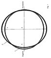
- schematisch den Vergleich gebogener Rohrquerschnitt mit idealem Rohrquerschnitt,
-
Figur 2 - die Wanddickenverteilung in einem gebogenen Rohrquerschnitt,
-
Figur 3 - schematisch eine erfindungsgemäß ausgebildete Induktivbiegeanlage,
-
Figur 4 - eine Ansicht in Richtung X in
Figur 3.
- FIG. 1
- schematically the comparison of bent pipe cross-section with ideal pipe cross section,
- FIG. 2
- the wall thickness distribution in a curved pipe cross section,
- FIG. 3
- schematically an inventively designed induction bending,
- FIG. 4
- a view in the direction X in Figure 3.
In Figur 1 ist zur Demonstration ein schematisch induktiv gebogener Rohrquerschnitt 2 in
einen idealen Rohrquerschnitt 1 eingezeichnet worden. In Figure 1 , a schematically inductively
Wie man gut erkennen kann, wird der ursprünglich nahezu kreisrunde Rohrquerschnitt 1
durch die beim Induktivbiegen einwirkenden Kräfte oval gedrückt. Wird mit X die waagerechte
Biegeebene bezeichnet, so wird deutlich, dass in der Y-Achse der Rohrquerschnitt 2
nach außen wandert und außerhalb des idealen Rohrquerschnittes 1 liegt und umgekehrt
in der X-Achse der gebogene Rohrquerschnitt 2 nach innen wandert und zumindest auf
einer Seite vollständig innerhalb des idealen Rohrquerschnittes 1 liegt.As you can see well, the originally nearly circular tube cross section becomes 1
pressed oval by the forces acting on the inductive bending. Is the horizontal with X
Bending plane, it is clear that in the Y-axis of the
Figur 2 zeigt den gleichen Querschnitt 2 eines Bogenabschnittes wie Figur 1 aber mit
einer übertriebenen Darstellung der Wanddicke. In bekannter Weise wird das
Ausgangsrohr durch die einwirkenden Kräfte beim Induktivbiegen nicht nur oval gedrückt,
sondern gleichzeitig wird die Wanddicke 3 in der Zugzone verringert und die Wanddicke 4
in der Druckzone angestaucht. Figure 2 shows the
In Figur 3 ist schematisch eine erfindungsgemäß ausgebildete Induktivbiegeanlage 5
dargestellt. Sie besteht aus einem hier nur angedeuteten wassergekühlten Induktor 6,
einem Klemmelement 7 mit einem daran befestigten Biegearm 8. Die Fluchtlinien vom
Induktor 6 und vom Biegearm 8 schneiden sich im Drehpunkt 9. FIG. 3 schematically illustrates an inventive
Der Biegevorgang läuft nun in der Weise ab, dass das Ausgangsrohr 10 mittels des Induktors
6 in einem schmalen Streifen über den Umfang erwärmt wird. Das am stirnseitigen
Ende angebrachte Klemmelement 7 ist mit einem Biegearm 8 verbunden, der
entsprechend dem Vorschub langsam geschwenkt wird. Durch die Schwenkung wirken
Kräfte auf den erwärmten schmalen Streifen des Ausgangsrohres 10 ein und zwingen es
der durch den Biegeradius R festgelegten Kurvenbahn zu folgen.The bending process now proceeds in such a way that the
Um den in den Figuren 1 und 2 dargestellten Effekt einer Ovalisierung entgegenzuwirken
ist erfindungsgemäß hinter dem Induktor 6 ein Gerüst 11 angeordnet. In diesem
Ausführungsbeispiel ist es mit drei, vorzugsweise hydraulisch anstellbaren, Druckrollen 14,
14', 14" (siehe Figur 4) bestückt. Vorzugsweise haben die Druckrollen 14, 14', 14" im
Querschnitt gesehen eine Diaboloform.In order to counteract the effect of ovalization shown in FIGS. 1 and 2 , according to the invention a
Andeutungsweise sind die die Anstellung der Druckrollen betätigenden Hydraulikaggregate
12, 13, 13' dargestellt. Sie sind in diesem Ausführungsbeispiel so angeordnet, dass in der
Y-Achse zwei 13, 13' näherungsweise einander gegenüber liegen und in der X-Achse sich
ein Hydraulikaggregat 12 im Druckzonenbereich befindet. Die an den Hydraulikaggregaten
13, 13' eingezeichneten Umfangspfeile sollen die Möglichkeit andeuten, die optimale
Position variabel einstellen zu können. Andeutungsweise are the employment of the pressure rollers actuated
Claims (11)
- Method for induction-bending of pipes, in particular large pipes, on an induction-bending unit in which, during the bending process, a pressure, which acts on the pipe, is exerted directly after the heating zone,
characterised in that
the arc portion respectively, which is leaving the heating zone, is guided with force in a plane, which has selected the largest ovality to be expected, at at least two positions of the circumference to the nominal outer diameter of the pipe arc, the plane intersecting the centre of rotation of the bending arm (8) of the induction-bending unit in the rear extension. - Method according to claim 1,
characterised in that
the guiding force is exerted for the first time when the first arc portion has achieved an arc extension which is required for application of a guiding means. - Method according to claim 1 and 2,
characterised in that
the guiding force is exerted at two positions of the circumference which are situated opposite each other. - Method according to claim 3,
characterised in that
the plane of the guiding force coincides nearly with the perpendicular bending plane. - Method according to claim 1 and 2,
characterised in that
the guiding force is exerted at three positions which are disposed distributed over the circumference. - Method according to claim 5,
characterised in that
the third position of the guiding force lies in the horizontal bending plane in the pressure zone region. - Method according to one of the claims 1 to 6,
characterised in that
the number, the position and the spacings of the positions of the guiding force are determined by estimation or calculation. - Device for implementing the method according to claim 1, having a water-cooled inductor (6), a bending arm (8) and a frame (11), which is disposed behind the inductor, in which continuously radially adjustable pressure rollers (14, 14', 14") are mounted,
characterised in that
at least two pressure rollers (14, 14', 14"), which are displaceable in the circumferential direction, are disposed, said rollers being adjustable rigidly to a prescribable spacing during the bending process. - Device according to claim 8,
characterised in that
two pressure rollers are provided which are situated opposite each other. - Device according to claim 8 and 9,
characterised in that
the adjustment device for the pressure rollers is provided with a limit stop. - Device according to claim 9,
characterised in that
the displacement of the two pressure rollers, which are situated opposite each other, is connected mutually.
Applications Claiming Priority (2)
| Application Number | Priority Date | Filing Date | Title |
|---|---|---|---|
| DE10240341A DE10240341A1 (en) | 2002-08-27 | 2002-08-27 | Method and device for inductively bending pipes |
| DE10240341 | 2002-08-27 |
Publications (2)
| Publication Number | Publication Date |
|---|---|
| EP1393832A1 EP1393832A1 (en) | 2004-03-03 |
| EP1393832B1 true EP1393832B1 (en) | 2005-03-23 |
Family
ID=31197559
Family Applications (1)
| Application Number | Title | Priority Date | Filing Date |
|---|---|---|---|
| EP03090269A Expired - Lifetime EP1393832B1 (en) | 2002-08-27 | 2003-08-26 | Method and device for induction-bending of pipes |
Country Status (5)
| Country | Link |
|---|---|
| EP (1) | EP1393832B1 (en) |
| AT (1) | ATE291504T1 (en) |
| DE (2) | DE10240341A1 (en) |
| ES (1) | ES2236664T3 (en) |
| PL (1) | PL204409B1 (en) |
Cited By (1)
| Publication number | Priority date | Publication date | Assignee | Title |
|---|---|---|---|---|
| CN103447360A (en) * | 2013-08-26 | 2013-12-18 | 河南省驰源石油化工机械有限公司 | Device for producing arc-shaped steel pipes |
Families Citing this family (7)
| Publication number | Priority date | Publication date | Assignee | Title |
|---|---|---|---|---|
| KR20110105397A (en) * | 2009-01-14 | 2011-09-26 | 수미도모 메탈 인더스트리즈, 리미티드 | Hollow member, and manufacturing device and manufacturing method therefor |
| CN103170810B (en) * | 2013-04-17 | 2015-03-25 | 二重集团(德阳)重型装备股份有限公司 | Bead-welding method of inner wall of 90-degree bent pipe |
| CN104097017B (en) * | 2014-07-26 | 2016-08-24 | 唐山开元特种焊接设备有限公司 | A kind of bend pipe built-up welder |
| CN104690117B (en) * | 2015-03-27 | 2017-03-01 | 华电重工股份有限公司 | The especially big radius elbow of large diameter thick wall steel pipe and its forming method |
| DE102015106571A1 (en) * | 2015-04-28 | 2016-11-03 | AWS Schäfer Technologie GmbH | Method for induction bending forming of a pressure-resistant pipe with large wall thickness and large diameter and induction tube bending device |
| CN109047379B (en) * | 2018-10-11 | 2024-03-08 | 浙江工业大学之江学院 | Quick detection mechanism for ovality of cross section of space bent pipe |
| CN112372318B (en) * | 2020-11-05 | 2021-10-15 | 湖南翰坤实业有限公司 | Bending forming device for rectangular frame |
Family Cites Families (5)
| Publication number | Priority date | Publication date | Assignee | Title |
|---|---|---|---|---|
| US3902344A (en) * | 1974-04-01 | 1975-09-02 | Rollmet Inc | Tube bending method |
| GB1487520A (en) * | 1975-07-23 | 1977-10-05 | Daiichi Koshuha Kogyo Kk | Method and apparatus for bending metal pipes bars or rods |
| JPS5626625A (en) * | 1979-08-13 | 1981-03-14 | Dai Ichi High Frequency Co Ltd | Method and apparatus for preventing flattening at hot bending work for pipe |
| DE3150381A1 (en) * | 1981-12-16 | 1983-06-23 | Mannesmann AG, 4000 Düsseldorf | Method and installation for avoiding ovality in the bending of tubes |
| JPS59185527A (en) * | 1983-04-07 | 1984-10-22 | Mitsubishi Heavy Ind Ltd | Method and device for bending pipe by high frequency bender |
-
2002
- 2002-08-27 DE DE10240341A patent/DE10240341A1/en not_active Withdrawn
-
2003
- 2003-08-26 AT AT03090269T patent/ATE291504T1/en not_active IP Right Cessation
- 2003-08-26 EP EP03090269A patent/EP1393832B1/en not_active Expired - Lifetime
- 2003-08-26 DE DE50300381T patent/DE50300381D1/en not_active Expired - Lifetime
- 2003-08-26 ES ES03090269T patent/ES2236664T3/en not_active Expired - Lifetime
- 2003-08-27 PL PL361869A patent/PL204409B1/en not_active IP Right Cessation
Cited By (1)
| Publication number | Priority date | Publication date | Assignee | Title |
|---|---|---|---|---|
| CN103447360A (en) * | 2013-08-26 | 2013-12-18 | 河南省驰源石油化工机械有限公司 | Device for producing arc-shaped steel pipes |
Also Published As
| Publication number | Publication date |
|---|---|
| PL204409B1 (en) | 2010-01-29 |
| ATE291504T1 (en) | 2005-04-15 |
| PL361869A1 (en) | 2004-03-08 |
| ES2236664T3 (en) | 2005-07-16 |
| EP1393832A1 (en) | 2004-03-03 |
| DE10240341A1 (en) | 2004-03-18 |
| DE50300381D1 (en) | 2005-04-28 |
Similar Documents
| Publication | Publication Date | Title |
|---|---|---|
| DE2532735C3 (en) | Device for hot bending of metal pipes | |
| EP0296317B1 (en) | Method and device for bending a sheet metal | |
| DE102007012316B9 (en) | Method and bending press for bending the edge strips of a planar sheet to be formed into a slotted pipe | |
| EP1393832B1 (en) | Method and device for induction-bending of pipes | |
| DE2738394C2 (en) | Method for bending pipes or similar workpieces and device for carrying out the method | |
| EP1807226B1 (en) | Method and bending press for bending the boundary edge of a sheet for shaping into an open seam tube | |
| DE2257981A1 (en) | METHOD AND DEVICE FOR PULLING PIPES | |
| DE2642583A1 (en) | WELDING MACHINE FOR JOINING STRIP STEEL SECTIONS OR ROLLS | |
| EP1448323A1 (en) | Device for production of a tube | |
| DE2818909C2 (en) | Straightening machine for bars, tubes or similar workpieces | |
| DE1016675B (en) | Device for rounding sheet metal strips for the production of welded pipes with longitudinal seams, especially those of larger diameter | |
| DE2559694C3 (en) | Device for hot bending of metal pipes | |
| DE19512646B4 (en) | Method and device for final bending of a pre-bent pipe | |
| DE102006026136B3 (en) | Device for forming hollow profiles | |
| EP0876228B1 (en) | Process and device for producing pipes as per the uoe-process | |
| DE102015102271A1 (en) | Method and device for straightening metallic parts with a reduction of pinch edges | |
| EP0429815B1 (en) | Device for forming of a flange or similar, in particular at the end of a thin walled metalpipe | |
| DE2337377C3 (en) | Device for straightening Profüträgem | |
| EP0182003A2 (en) | Cross-roll straightening machine with more than two straightening rolls | |
| DE102020106664B4 (en) | Method and device for bending profiles with variable cross-sections | |
| DE102016105838A1 (en) | Apparatus and method for post bending a preformed pipe | |
| DE2804019C3 (en) | Device for bending a pipe into a pipe bend | |
| DE1937285C3 (en) | Method and device for beading and flanging a pipe by roller burnishing | |
| DE1552992C3 (en) | Device for the production of corrugated or folded pipe bends | |
| DE3150381A1 (en) | Method and installation for avoiding ovality in the bending of tubes |
Legal Events
| Date | Code | Title | Description |
|---|---|---|---|
| PUAI | Public reference made under article 153(3) epc to a published international application that has entered the european phase |
Free format text: ORIGINAL CODE: 0009012 |
|
| AK | Designated contracting states |
Kind code of ref document: A1 Designated state(s): AT BE BG CH CY CZ DE DK EE ES FI FR GB GR HU IE IT LI LU MC NL PT RO SE SI SK TR |
|
| AX | Request for extension of the european patent |
Extension state: AL LT LV MK |
|
| 17P | Request for examination filed |
Effective date: 20040212 |
|
| GRAP | Despatch of communication of intention to grant a patent |
Free format text: ORIGINAL CODE: EPIDOSNIGR1 |
|
| AKX | Designation fees paid |
Designated state(s): AT BE BG CH CY CZ DE DK EE ES FI FR GB GR HU IE IT LI LU MC NL PT RO SE SI SK TR |
|
| GRAS | Grant fee paid |
Free format text: ORIGINAL CODE: EPIDOSNIGR3 |
|
| GRAA | (expected) grant |
Free format text: ORIGINAL CODE: 0009210 |
|
| AK | Designated contracting states |
Kind code of ref document: B1 Designated state(s): AT BE BG CH CY CZ DE DK EE ES FI FR GB GR HU IE IT LI LU MC NL PT RO SE SI SK TR |
|
| PG25 | Lapsed in a contracting state [announced via postgrant information from national office to epo] |
Ref country code: TR Free format text: LAPSE BECAUSE OF FAILURE TO SUBMIT A TRANSLATION OF THE DESCRIPTION OR TO PAY THE FEE WITHIN THE PRESCRIBED TIME-LIMIT Effective date: 20050323 Ref country code: FI Free format text: LAPSE BECAUSE OF FAILURE TO SUBMIT A TRANSLATION OF THE DESCRIPTION OR TO PAY THE FEE WITHIN THE PRESCRIBED TIME-LIMIT Effective date: 20050323 Ref country code: IE Free format text: LAPSE BECAUSE OF FAILURE TO SUBMIT A TRANSLATION OF THE DESCRIPTION OR TO PAY THE FEE WITHIN THE PRESCRIBED TIME-LIMIT Effective date: 20050323 Ref country code: EE Free format text: LAPSE BECAUSE OF FAILURE TO SUBMIT A TRANSLATION OF THE DESCRIPTION OR TO PAY THE FEE WITHIN THE PRESCRIBED TIME-LIMIT Effective date: 20050323 Ref country code: SK Free format text: LAPSE BECAUSE OF FAILURE TO SUBMIT A TRANSLATION OF THE DESCRIPTION OR TO PAY THE FEE WITHIN THE PRESCRIBED TIME-LIMIT Effective date: 20050323 Ref country code: RO Free format text: LAPSE BECAUSE OF FAILURE TO SUBMIT A TRANSLATION OF THE DESCRIPTION OR TO PAY THE FEE WITHIN THE PRESCRIBED TIME-LIMIT Effective date: 20050323 Ref country code: SI Free format text: LAPSE BECAUSE OF FAILURE TO SUBMIT A TRANSLATION OF THE DESCRIPTION OR TO PAY THE FEE WITHIN THE PRESCRIBED TIME-LIMIT Effective date: 20050323 |
|
| REG | Reference to a national code |
Ref country code: GB Ref legal event code: FG4D Free format text: NOT ENGLISH |
|
| REG | Reference to a national code |
Ref country code: CH Ref legal event code: EP |
|
| GBT | Gb: translation of ep patent filed (gb section 77(6)(a)/1977) |
Effective date: 20050323 |
|
| REG | Reference to a national code |
Ref country code: IE Ref legal event code: FG4D Free format text: GERMAN |
|
| REF | Corresponds to: |
Ref document number: 50300381 Country of ref document: DE Date of ref document: 20050428 Kind code of ref document: P |
|
| PG25 | Lapsed in a contracting state [announced via postgrant information from national office to epo] |
Ref country code: GR Free format text: LAPSE BECAUSE OF FAILURE TO SUBMIT A TRANSLATION OF THE DESCRIPTION OR TO PAY THE FEE WITHIN THE PRESCRIBED TIME-LIMIT Effective date: 20050623 Ref country code: BG Free format text: LAPSE BECAUSE OF FAILURE TO SUBMIT A TRANSLATION OF THE DESCRIPTION OR TO PAY THE FEE WITHIN THE PRESCRIBED TIME-LIMIT Effective date: 20050623 Ref country code: DK Free format text: LAPSE BECAUSE OF FAILURE TO SUBMIT A TRANSLATION OF THE DESCRIPTION OR TO PAY THE FEE WITHIN THE PRESCRIBED TIME-LIMIT Effective date: 20050623 |
|
| PG25 | Lapsed in a contracting state [announced via postgrant information from national office to epo] |
Ref country code: HU Free format text: LAPSE BECAUSE OF FAILURE TO SUBMIT A TRANSLATION OF THE DESCRIPTION OR TO PAY THE FEE WITHIN THE PRESCRIBED TIME-LIMIT Effective date: 20050624 |
|
| REG | Reference to a national code |
Ref country code: ES Ref legal event code: FG2A Ref document number: 2236664 Country of ref document: ES Kind code of ref document: T3 |
|
| PG25 | Lapsed in a contracting state [announced via postgrant information from national office to epo] |
Ref country code: LU Free format text: LAPSE BECAUSE OF NON-PAYMENT OF DUE FEES Effective date: 20050826 Ref country code: AT Free format text: LAPSE BECAUSE OF NON-PAYMENT OF DUE FEES Effective date: 20050826 Ref country code: CY Free format text: LAPSE BECAUSE OF FAILURE TO SUBMIT A TRANSLATION OF THE DESCRIPTION OR TO PAY THE FEE WITHIN THE PRESCRIBED TIME-LIMIT Effective date: 20050826 |
|
| PG25 | Lapsed in a contracting state [announced via postgrant information from national office to epo] |
Ref country code: MC Free format text: LAPSE BECAUSE OF NON-PAYMENT OF DUE FEES Effective date: 20050831 |
|
| PG25 | Lapsed in a contracting state [announced via postgrant information from national office to epo] |
Ref country code: PT Free format text: LAPSE BECAUSE OF FAILURE TO SUBMIT A TRANSLATION OF THE DESCRIPTION OR TO PAY THE FEE WITHIN THE PRESCRIBED TIME-LIMIT Effective date: 20050907 |
|
| REG | Reference to a national code |
Ref country code: IE Ref legal event code: FD4D |
|
| ET | Fr: translation filed | ||
| PLBE | No opposition filed within time limit |
Free format text: ORIGINAL CODE: 0009261 |
|
| STAA | Information on the status of an ep patent application or granted ep patent |
Free format text: STATUS: NO OPPOSITION FILED WITHIN TIME LIMIT |
|
| 26N | No opposition filed |
Effective date: 20051227 |
|
| PG25 | Lapsed in a contracting state [announced via postgrant information from national office to epo] |
Ref country code: SE Free format text: LAPSE BECAUSE OF FAILURE TO SUBMIT A TRANSLATION OF THE DESCRIPTION OR TO PAY THE FEE WITHIN THE PRESCRIBED TIME-LIMIT Effective date: 20050623 |
|
| REG | Reference to a national code |
Ref country code: CH Ref legal event code: PL |
|
| PG25 | Lapsed in a contracting state [announced via postgrant information from national office to epo] |
Ref country code: LI Free format text: LAPSE BECAUSE OF NON-PAYMENT OF DUE FEES Effective date: 20070831 Ref country code: CH Free format text: LAPSE BECAUSE OF NON-PAYMENT OF DUE FEES Effective date: 20070831 |
|
| PGFP | Annual fee paid to national office [announced via postgrant information from national office to epo] |
Ref country code: ES Payment date: 20090821 Year of fee payment: 7 |
|
| PGFP | Annual fee paid to national office [announced via postgrant information from national office to epo] |
Ref country code: GB Payment date: 20090827 Year of fee payment: 7 Ref country code: NL Payment date: 20090814 Year of fee payment: 7 |
|
| REG | Reference to a national code |
Ref country code: NL Ref legal event code: V1 Effective date: 20110301 |
|
| GBPC | Gb: european patent ceased through non-payment of renewal fee |
Effective date: 20100826 |
|
| PG25 | Lapsed in a contracting state [announced via postgrant information from national office to epo] |
Ref country code: NL Free format text: LAPSE BECAUSE OF NON-PAYMENT OF DUE FEES Effective date: 20110301 |
|
| PG25 | Lapsed in a contracting state [announced via postgrant information from national office to epo] |
Ref country code: GB Free format text: LAPSE BECAUSE OF NON-PAYMENT OF DUE FEES Effective date: 20100826 |
|
| REG | Reference to a national code |
Ref country code: ES Ref legal event code: FD2A Effective date: 20111019 |
|
| PG25 | Lapsed in a contracting state [announced via postgrant information from national office to epo] |
Ref country code: ES Free format text: LAPSE BECAUSE OF NON-PAYMENT OF DUE FEES Effective date: 20100827 |
|
| PGFP | Annual fee paid to national office [announced via postgrant information from national office to epo] |
Ref country code: FR Payment date: 20130823 Year of fee payment: 11 |
|
| PGFP | Annual fee paid to national office [announced via postgrant information from national office to epo] |
Ref country code: CZ Payment date: 20140821 Year of fee payment: 12 Ref country code: DE Payment date: 20140821 Year of fee payment: 12 |
|
| PGFP | Annual fee paid to national office [announced via postgrant information from national office to epo] |
Ref country code: IT Payment date: 20140826 Year of fee payment: 12 |
|
| PGFP | Annual fee paid to national office [announced via postgrant information from national office to epo] |
Ref country code: BE Payment date: 20140820 Year of fee payment: 12 |
|
| REG | Reference to a national code |
Ref country code: FR Ref legal event code: ST Effective date: 20150430 |
|
| PG25 | Lapsed in a contracting state [announced via postgrant information from national office to epo] |
Ref country code: FR Free format text: LAPSE BECAUSE OF NON-PAYMENT OF DUE FEES Effective date: 20140901 |
|
| REG | Reference to a national code |
Ref country code: DE Ref legal event code: R119 Ref document number: 50300381 Country of ref document: DE |
|
| PG25 | Lapsed in a contracting state [announced via postgrant information from national office to epo] |
Ref country code: CZ Free format text: LAPSE BECAUSE OF NON-PAYMENT OF DUE FEES Effective date: 20150826 Ref country code: IT Free format text: LAPSE BECAUSE OF NON-PAYMENT OF DUE FEES Effective date: 20150826 |
|
| PG25 | Lapsed in a contracting state [announced via postgrant information from national office to epo] |
Ref country code: DE Free format text: LAPSE BECAUSE OF NON-PAYMENT OF DUE FEES Effective date: 20160301 |
|
| PG25 | Lapsed in a contracting state [announced via postgrant information from national office to epo] |
Ref country code: BE Free format text: LAPSE BECAUSE OF NON-PAYMENT OF DUE FEES Effective date: 20150831 |