EP1393804A1 - Mehrschichtiger Katalysator zur autothermen Dampfreformierung von Kohlenwasserstoffen und Verfahren zu seiner Verwendung - Google Patents
Mehrschichtiger Katalysator zur autothermen Dampfreformierung von Kohlenwasserstoffen und Verfahren zu seiner Verwendung Download PDFInfo
- Publication number
- EP1393804A1 EP1393804A1 EP02019014A EP02019014A EP1393804A1 EP 1393804 A1 EP1393804 A1 EP 1393804A1 EP 02019014 A EP02019014 A EP 02019014A EP 02019014 A EP02019014 A EP 02019014A EP 1393804 A1 EP1393804 A1 EP 1393804A1
- Authority
- EP
- European Patent Office
- Prior art keywords
- catalyst
- catalyst layer
- oxides
- layer
- hydrocarbons
- Prior art date
- Legal status (The legal status is an assumption and is not a legal conclusion. Google has not performed a legal analysis and makes no representation as to the accuracy of the status listed.)
- Withdrawn
Links
Images
Classifications
-
- B—PERFORMING OPERATIONS; TRANSPORTING
- B01—PHYSICAL OR CHEMICAL PROCESSES OR APPARATUS IN GENERAL
- B01J—CHEMICAL OR PHYSICAL PROCESSES, e.g. CATALYSIS OR COLLOID CHEMISTRY; THEIR RELEVANT APPARATUS
- B01J23/00—Catalysts comprising metals or metal oxides or hydroxides, not provided for in group B01J21/00
- B01J23/38—Catalysts comprising metals or metal oxides or hydroxides, not provided for in group B01J21/00 of noble metals
- B01J23/40—Catalysts comprising metals or metal oxides or hydroxides, not provided for in group B01J21/00 of noble metals of the platinum group metals
- B01J23/46—Ruthenium, rhodium, osmium or iridium
- B01J23/464—Rhodium
-
- B—PERFORMING OPERATIONS; TRANSPORTING
- B01—PHYSICAL OR CHEMICAL PROCESSES OR APPARATUS IN GENERAL
- B01J—CHEMICAL OR PHYSICAL PROCESSES, e.g. CATALYSIS OR COLLOID CHEMISTRY; THEIR RELEVANT APPARATUS
- B01J23/00—Catalysts comprising metals or metal oxides or hydroxides, not provided for in group B01J21/00
- B01J23/38—Catalysts comprising metals or metal oxides or hydroxides, not provided for in group B01J21/00 of noble metals
- B01J23/40—Catalysts comprising metals or metal oxides or hydroxides, not provided for in group B01J21/00 of noble metals of the platinum group metals
-
- B—PERFORMING OPERATIONS; TRANSPORTING
- B01—PHYSICAL OR CHEMICAL PROCESSES OR APPARATUS IN GENERAL
- B01J—CHEMICAL OR PHYSICAL PROCESSES, e.g. CATALYSIS OR COLLOID CHEMISTRY; THEIR RELEVANT APPARATUS
- B01J37/00—Processes, in general, for preparing catalysts; Processes, in general, for activation of catalysts
- B01J37/02—Impregnation, coating or precipitation
- B01J37/024—Multiple impregnation or coating
- B01J37/0244—Coatings comprising several layers
-
- C—CHEMISTRY; METALLURGY
- C01—INORGANIC CHEMISTRY
- C01B—NON-METALLIC ELEMENTS; COMPOUNDS THEREOF; METALLOIDS OR COMPOUNDS THEREOF NOT COVERED BY SUBCLASS C01C
- C01B3/00—Hydrogen; Gaseous mixtures containing hydrogen; Separation of hydrogen from mixtures containing it; Purification of hydrogen; Reversible storage of hydrogen
- C01B3/02—Production of hydrogen; Production of gaseous mixtures containing hydrogen
- C01B3/32—Production of hydrogen; Production of gaseous mixtures containing hydrogen by reaction of gaseous or liquid organic compounds with gasifying agents, e.g. water, carbon dioxide or air
- C01B3/34—Production of hydrogen; Production of gaseous mixtures containing hydrogen by reaction of gaseous or liquid organic compounds with gasifying agents, e.g. water, carbon dioxide or air by reaction of hydrocarbons with gasifying agents
- C01B3/38—Production of hydrogen; Production of gaseous mixtures containing hydrogen by reaction of gaseous or liquid organic compounds with gasifying agents, e.g. water, carbon dioxide or air by reaction of hydrocarbons with gasifying agents using catalysts
- C01B3/382—Processes with two or more reaction steps, of which at least one is catalytic, e.g. steam reforming and partial oxidation
-
- C—CHEMISTRY; METALLURGY
- C01—INORGANIC CHEMISTRY
- C01B—NON-METALLIC ELEMENTS; COMPOUNDS THEREOF; METALLOIDS OR COMPOUNDS THEREOF NOT COVERED BY SUBCLASS C01C
- C01B3/00—Hydrogen; Gaseous mixtures containing hydrogen; Separation of hydrogen from mixtures containing it; Purification of hydrogen; Reversible storage of hydrogen
- C01B3/02—Production of hydrogen; Production of gaseous mixtures containing hydrogen
- C01B3/32—Production of hydrogen; Production of gaseous mixtures containing hydrogen by reaction of gaseous or liquid organic compounds with gasifying agents, e.g. water, carbon dioxide or air
- C01B3/34—Production of hydrogen; Production of gaseous mixtures containing hydrogen by reaction of gaseous or liquid organic compounds with gasifying agents, e.g. water, carbon dioxide or air by reaction of hydrocarbons with gasifying agents
- C01B3/38—Production of hydrogen; Production of gaseous mixtures containing hydrogen by reaction of gaseous or liquid organic compounds with gasifying agents, e.g. water, carbon dioxide or air by reaction of hydrocarbons with gasifying agents using catalysts
- C01B3/40—Production of hydrogen; Production of gaseous mixtures containing hydrogen by reaction of gaseous or liquid organic compounds with gasifying agents, e.g. water, carbon dioxide or air by reaction of hydrocarbons with gasifying agents using catalysts characterised by the catalyst
-
- H—ELECTRICITY
- H01—ELECTRIC ELEMENTS
- H01M—PROCESSES OR MEANS, e.g. BATTERIES, FOR THE DIRECT CONVERSION OF CHEMICAL ENERGY INTO ELECTRICAL ENERGY
- H01M8/00—Fuel cells; Manufacture thereof
- H01M8/06—Combination of fuel cells with means for production of reactants or for treatment of residues
- H01M8/0606—Combination of fuel cells with means for production of reactants or for treatment of residues with means for production of gaseous reactants
- H01M8/0612—Combination of fuel cells with means for production of reactants or for treatment of residues with means for production of gaseous reactants from carbon-containing material
-
- C—CHEMISTRY; METALLURGY
- C01—INORGANIC CHEMISTRY
- C01B—NON-METALLIC ELEMENTS; COMPOUNDS THEREOF; METALLOIDS OR COMPOUNDS THEREOF NOT COVERED BY SUBCLASS C01C
- C01B2203/00—Integrated processes for the production of hydrogen or synthesis gas
- C01B2203/02—Processes for making hydrogen or synthesis gas
- C01B2203/0205—Processes for making hydrogen or synthesis gas containing a reforming step
- C01B2203/0227—Processes for making hydrogen or synthesis gas containing a reforming step containing a catalytic reforming step
- C01B2203/0244—Processes for making hydrogen or synthesis gas containing a reforming step containing a catalytic reforming step the reforming step being an autothermal reforming step, e.g. secondary reforming processes
-
- C—CHEMISTRY; METALLURGY
- C01—INORGANIC CHEMISTRY
- C01B—NON-METALLIC ELEMENTS; COMPOUNDS THEREOF; METALLOIDS OR COMPOUNDS THEREOF NOT COVERED BY SUBCLASS C01C
- C01B2203/00—Integrated processes for the production of hydrogen or synthesis gas
- C01B2203/02—Processes for making hydrogen or synthesis gas
- C01B2203/0283—Processes for making hydrogen or synthesis gas containing a CO-shift step, i.e. a water gas shift step
-
- C—CHEMISTRY; METALLURGY
- C01—INORGANIC CHEMISTRY
- C01B—NON-METALLIC ELEMENTS; COMPOUNDS THEREOF; METALLOIDS OR COMPOUNDS THEREOF NOT COVERED BY SUBCLASS C01C
- C01B2203/00—Integrated processes for the production of hydrogen or synthesis gas
- C01B2203/08—Methods of heating or cooling
- C01B2203/0805—Methods of heating the process for making hydrogen or synthesis gas
- C01B2203/0838—Methods of heating the process for making hydrogen or synthesis gas by heat exchange with exothermic reactions, other than by combustion of fuel
- C01B2203/0844—Methods of heating the process for making hydrogen or synthesis gas by heat exchange with exothermic reactions, other than by combustion of fuel the non-combustive exothermic reaction being another reforming reaction as defined in groups C01B2203/02 - C01B2203/0294
-
- C—CHEMISTRY; METALLURGY
- C01—INORGANIC CHEMISTRY
- C01B—NON-METALLIC ELEMENTS; COMPOUNDS THEREOF; METALLOIDS OR COMPOUNDS THEREOF NOT COVERED BY SUBCLASS C01C
- C01B2203/00—Integrated processes for the production of hydrogen or synthesis gas
- C01B2203/10—Catalysts for performing the hydrogen forming reactions
- C01B2203/1005—Arrangement or shape of catalyst
-
- C—CHEMISTRY; METALLURGY
- C01—INORGANIC CHEMISTRY
- C01B—NON-METALLIC ELEMENTS; COMPOUNDS THEREOF; METALLOIDS OR COMPOUNDS THEREOF NOT COVERED BY SUBCLASS C01C
- C01B2203/00—Integrated processes for the production of hydrogen or synthesis gas
- C01B2203/10—Catalysts for performing the hydrogen forming reactions
- C01B2203/1041—Composition of the catalyst
- C01B2203/1047—Group VIII metal catalysts
-
- C—CHEMISTRY; METALLURGY
- C01—INORGANIC CHEMISTRY
- C01B—NON-METALLIC ELEMENTS; COMPOUNDS THEREOF; METALLOIDS OR COMPOUNDS THEREOF NOT COVERED BY SUBCLASS C01C
- C01B2203/00—Integrated processes for the production of hydrogen or synthesis gas
- C01B2203/10—Catalysts for performing the hydrogen forming reactions
- C01B2203/1041—Composition of the catalyst
- C01B2203/1047—Group VIII metal catalysts
- C01B2203/1064—Platinum group metal catalysts
-
- C—CHEMISTRY; METALLURGY
- C01—INORGANIC CHEMISTRY
- C01B—NON-METALLIC ELEMENTS; COMPOUNDS THEREOF; METALLOIDS OR COMPOUNDS THEREOF NOT COVERED BY SUBCLASS C01C
- C01B2203/00—Integrated processes for the production of hydrogen or synthesis gas
- C01B2203/14—Details of the flowsheet
- C01B2203/142—At least two reforming, decomposition or partial oxidation steps in series
-
- C—CHEMISTRY; METALLURGY
- C01—INORGANIC CHEMISTRY
- C01B—NON-METALLIC ELEMENTS; COMPOUNDS THEREOF; METALLOIDS OR COMPOUNDS THEREOF NOT COVERED BY SUBCLASS C01C
- C01B2203/00—Integrated processes for the production of hydrogen or synthesis gas
- C01B2203/80—Aspect of integrated processes for the production of hydrogen or synthesis gas not covered by groups C01B2203/02 - C01B2203/1695
- C01B2203/82—Several process steps of C01B2203/02 - C01B2203/08 integrated into a single apparatus
-
- Y—GENERAL TAGGING OF NEW TECHNOLOGICAL DEVELOPMENTS; GENERAL TAGGING OF CROSS-SECTIONAL TECHNOLOGIES SPANNING OVER SEVERAL SECTIONS OF THE IPC; TECHNICAL SUBJECTS COVERED BY FORMER USPC CROSS-REFERENCE ART COLLECTIONS [XRACs] AND DIGESTS
- Y02—TECHNOLOGIES OR APPLICATIONS FOR MITIGATION OR ADAPTATION AGAINST CLIMATE CHANGE
- Y02E—REDUCTION OF GREENHOUSE GAS [GHG] EMISSIONS, RELATED TO ENERGY GENERATION, TRANSMISSION OR DISTRIBUTION
- Y02E60/00—Enabling technologies; Technologies with a potential or indirect contribution to GHG emissions mitigation
- Y02E60/30—Hydrogen technology
- Y02E60/50—Fuel cells
-
- Y—GENERAL TAGGING OF NEW TECHNOLOGICAL DEVELOPMENTS; GENERAL TAGGING OF CROSS-SECTIONAL TECHNOLOGIES SPANNING OVER SEVERAL SECTIONS OF THE IPC; TECHNICAL SUBJECTS COVERED BY FORMER USPC CROSS-REFERENCE ART COLLECTIONS [XRACs] AND DIGESTS
- Y02—TECHNOLOGIES OR APPLICATIONS FOR MITIGATION OR ADAPTATION AGAINST CLIMATE CHANGE
- Y02P—CLIMATE CHANGE MITIGATION TECHNOLOGIES IN THE PRODUCTION OR PROCESSING OF GOODS
- Y02P20/00—Technologies relating to chemical industry
- Y02P20/50—Improvements relating to the production of bulk chemicals
- Y02P20/52—Improvements relating to the production of bulk chemicals using catalysts, e.g. selective catalysts
Definitions
- the invention relates to a multilayer catalyst for the production of Hydrogen through autothermal steam reforming.
- the invention further relates to a Process for the autothermal steam reforming of hydrocarbons Using this catalyst. This will turn on a preheat temperature heated educt mixture of hydrocarbons, oxygen and water or Water vapor passed over a multilayer catalyst, which in the It is capable of both partial oxidation and steam reforming of Catalyze hydrocarbons.
- the method is used for generation of hydrogen or hydrogen-containing fuel gases in reformer systems for Fuel cells.
- CPO Catalytic Partial Oxidation
- the present invention is concerned with a further possibility of Hydrogen production, the so-called autothermal steam reforming.
- This The process combines steam reforming (equation (1)) with the catalytic partial oxidation (equation (2)), the exothermic, partial oxidation being the provides the necessary heat of reaction for endothermic steam reforming.
- the starting material mixture can be preheated to a preheating temperature.
- the product mixture is at the temperature prevailing at the reactor outlet in thermodynamic equilibrium.
- the autothermal steam reforming connects the Advantages of the catalytic partial oxidation (good starting behavior) with those of the Steam reforming (high hydrogen yields).
- the process is therefore well suited for the on-board generation of hydrogen for mobile fuel cell systems also for use in compact reformers for stationary fuel cell systems.
- US-A-4,415,484 discloses a catalyst for use in an autothermal Reforming reactor.
- the catalyst contains 0.01 to 6% rhodium and 10 to 35 % Calcium oxide on a support made of aluminum oxide, which in addition about 3 contains up to 15% magnesium oxide.
- the catalyst is used in the form of pellets and is particularly characterized by a low tendency to coke at low Oxygen / carbon ratios.
- a typical catalyst system for Implementation of the autothermal reforming contains approximately according to this document a third of its length is an iron oxide catalyst for partial oxidation and the rhodium catalyst described over two thirds of its length. On multilayer catalyst structure is not described.
- WO 98/55227 describes a bifunctional catalyst for the partial oxidation of hydrocarbons, which is both an activity for the dehydrogenation of the Owns hydrocarbons as well as has the ability to hydrocarbon chain to oxidize selectively.
- the dehydrogenation activity is caused by metals of the 8th group of the Periodic table provided during the selective oxidation by ionized oxygen takes place.
- Oxides are the source of ionized oxygen Crystallize fluorite structure or a perovskite structure such as zirconium oxide, Cerium oxide, bismuth oxide, etc.
- a preferred catalyst is Pt / CeGdO, for example. He comes in pellet form with diameters from 1.125 to 1.5 inches (2.8 to 3.8 cm) used.
- WO 99/48805 describes a process for the catalytic generation of hydrogen through a self-sustaining, partial oxidation and steam reforming of Hydrocarbons, a mixture of the hydrocarbons and one Oxygen-containing gas and optionally steam reacted on a catalyst , which contains rhodium dispersed on a carrier material, which as cations Contains cerium and zircon.
- the catalyst is used in granular form. On multilayer structure of the catalyst is not described.
- DE 197 27 841 A1 describes a method and a device for autothermal Reforming of hydrocarbons in which the fuel has a Feed device is fed to a two-stage reforming reactor.
- the emerging reformate is in a heat exchanger in counterflow and in heat-exchanging to raw materials from outside to inside Reformed.
- the fuel supplied via the feed device is with the starting material directly to the reaction zone having a catalyst applied in which the combustion and reforming or catalysis performed becomes.
- the reforming reactor contains an upper part with a catalyst coated honeycomb body and in the lower area one with catalyst coated bed. A honeycomb body can also be used instead of the bed become.
- a multi-layer structure of the catalyst is not described here either.
- EP 0 112 613 B1 describes a process for the autothermal reforming of Hydrocarbons described in which the partial oxidation in Zone 1, the Steam reforming spatially separated from it, takes place in Zone 2.
- the partial Oxidation becomes Pt and Pd-containing catalysts for steam reforming Precious metal catalysts used.
- a multilayer structure of the Catalyst is not disclosed.
- WO 99/33567 describes catalysts for the partial oxidation of Hydrocarbons whose monolithic supports have a multi-layer structure have different porosity.
- the multilayer refers Structure not on the catalyst itself, but on the carrier substrate.
- the catalyst system contains a first catalytic one Component based on copper oxide and zinc oxide, which acts as the lower layer mainly catalyzes steam reforming, as well as a second, upper catalytic one Layer containing a noble metal (platinum or palladium) and a metal oxide and the mainly the partial oxidation of methanol activated.
- the one described here Catalyst system is for the autothermal reforming of hydrocarbons however not usable because of the higher decomposition temperatures or reduction of the base metal oxides (CuO, ZnO) and subsequently to one Alloy formation comes with the precious metal component, so long-term stability is not given.
- the invention provides a catalyst and a method for autothermal, catalytic Steam reforming of hydrocarbons using this catalyst ready.
- the catalyst according to the invention has a multilayer on a support body Coating immense two different catalyst layers, each one contain at least one platinum group metal on an oxidic support material.
- the multilayer coating has in addition to a first, lower catalyst layer, the preferably catalyzes the partial oxidation ("CPO" according to Eq. (2)), a second, top catalyst layer, which is mainly an activity related to the Steam reforming (according to Eq. (1)).
- CPO partial oxidation
- a second, top catalyst layer which is mainly an activity related to the Steam reforming (according to Eq. (1)).
- the Layer sequence apart from the different catalyst components, vice versa.
- a preheat temperature is reached heated educt mixture of hydrocarbons, oxygen and water or Water vapor is passed over the catalyst, an adiabatic Reaction is carried out.
- the process is one-step, that is The starting material mixture is passed over a single, multilayer catalyst which is in the Is able, by the catalytic, partial oxidation of the starting material mixture for the to provide the energy required for endothermic steam reforming.
- This increases the temperature of the educt mixture from the preheating temperature to the necessary Reaction temperature between 600 and 900 ° C.
- Partial oxidation and Steam reforming flows smoothly into one another on the catalytic converter.
- the sequence of exothermic catalytic, partial oxidation and endothermic steam reforming result in a uniform temperature profile in the catalyst that is not large Temperature fluctuations and peaks.
- the catalyst according to the invention contains a catalyst mass on a support body, which in the form of a multiple coating on the geometric surfaces of the Carrier body is applied.
- Preferred supporting bodies are monolithic honeycomb bodies made of ceramic or metal, open-cell ceramic or metallic foam body, Metal sheets or irregularly shaped components.
- the total thickness of the catalytic Coating is usually between 20 and 200 ⁇ m.
- the catalyst mass contains, in addition to a first, lower catalyst layer, which preferably catalyzes the partial oxidation, a second, upper catalyst layer which has an activity with regard to steam reforming.
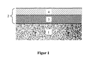
- FIG. 1 A schematic representation of a possible structure of the catalyst according to the invention is shown in FIG. 1 .
- the catalyst comprises a support body (1) on which a multilayer catalyst mass (2) is applied, which in turn comprises a lower layer (3) and an upper layer (4).
- the lower catalyst layer can catalyze the partial oxidation
- the upper catalyst layer can catalyze the steam reforming.
- the two different catalyst layers each contain at least one Platinum group metal on a finely divided, oxidic carrier material. It is about So so-called supported catalysts or supported catalysts, in which the Precious metal in a high distribution (i.e. dispersion) on the oxidic carrier material is applied.
- supported catalyst refers to this Invention only on the catalyst mass and must be differentiated from the catalyst the carrier body (1) with the catalyst mass (2) applied to it includes.
- the lower catalyst layer (3) which catalyzes the partial oxidation, contains as Precious metal preferably 0.1 to 5 wt .-% platinum, based on their total weight.
- platinum has a high activity for the oxidation of hydrocarbons.
- the oxidation activity can be adapted to the requirements of the process
- a catalyst mass which contains platinum is preferably used Contains alumina and rare earth oxides.
- the upper catalyst layer (4) (for steam reforming) contains noble metal preferably 0.1 to 5% by weight of rhodium, based on their total weight. Rhodium points a high activity for steam reforming while maintaining its Oxidation activity is low compared to that of platinum.
- Suitable oxidic carrier materials for the platinum group metals are oxides such as aluminum oxide, silicon dioxide, titanium dioxide or mixed oxides thereof and zeolites. Materials with a specific surface area of more than 10 m 2 / g are preferably used in order to enable a highly disperse distribution of the catalytically active components on this large surface area.
- the techniques for producing such a supported catalyst and for coating an inert support body with it are known to the person skilled in the art.
- the catalyst mass can additionally have at least one Oxide selected from boron oxide, bismuth oxide, gallium oxide, oxides of the alkali metals, Oxides of alkaline earth metals, oxides of subgroup elements and oxides of Rare earth metals, for example in a concentration of up to 40 wt .-%, based on the total weight of the catalyst mass.
- Oxide selected from boron oxide, bismuth oxide, gallium oxide, oxides of the alkali metals, Oxides of alkaline earth metals, oxides of subgroup elements and oxides of Rare earth metals, for example in a concentration of up to 40 wt .-%, based on the total weight of the catalyst mass.
- the multilayer catalyst according to the invention has considerable advantages conventional catalysts. So the inventors found that Surprisingly, by applying the upper catalyst layer (for Steam reforming) on the lower, oxidation-active layer overall the partial Oxidation of the starting material mixture is damped at the inlet of the catalyst. Thereby high temperature peaks are avoided, which could destroy the catalyst. In addition, the yield of hydrogen is increased and the content of Residual hydrocarbons, especially methane, are lowered
- the process can be carried out using aliphatic and / or aromatic hydrocarbons (methane, Propane, toluene etc.) or hydrocarbon mixtures (e.g. natural gas, gasoline, heating oil or diesel oil) are operated.
- the Air ratio ⁇ of the educt mixture and its preheating temperature should be chosen that there is a temperature between 600 and 900 ° C at the outlet of the catalyst established.
- the proposed procedure provides only part of an overall procedure Obtaining hydrogen for mobile and stationary fuel cell units.
- the entire process includes autothermal reforming Process steps for removing carbon monoxide from the reformate, for example by one or more water gas shift stages.
- the reaction in the Water gas shift stages are exothermic and can be in continuous operation of the reformer unit
- the amount of heat required to preheat the educt mixture to a suitable one Provide preheating temperature between about 270 and 350 ° C, for example. to
- the reactant mixture can also be put into operation quickly for a short time be electrically preheated.
- the low thermal mass of the catalyst leads Advantageously, the full after just a few seconds Hydrogen production begins.
- the catalyst mass can be on a monolithic support body, which has a length L and an entry face flow channels are applied up to an exit end face and a lower catalyst layer lying directly on the support body and one on the lower catalyst layer located upper catalyst layer.
- the lower layer over the entire length L of the supporting body, and the upper layer only on a certain segment, for example the outlet-side part of the supporting body applied.
- the exact design of the layer sequence depends on the Construction, the geometry and the mode of operation of the reformer system.
- the catalyst mass can be an additional one Catalyst layer, for example for carbon monoxide conversion, which is applied in whole or in part as a third layer on the second coating.
- the Catalyst layer for carbon monoxide conversion can be catalytically active Components of at least one of the noble metals Pt, Pd, Rh, Ru, Ir, Os and Au on one oxidic carrier material from the group aluminum oxide, silicon dioxide, titanium dioxide, Contain rare earth oxides or mixed oxides thereof or zeolites. Even more than three-layer structures, for example four-layer arrangements, are possible.
- Methane was reformed using the process according to the invention, a two-layer catalyst being used.
- the catalyst was a catalytically coated ceramic honeycomb body with a cell density of 62 cells / cm 2 and a volume of 30 ml.
- the lower layer of the two-layer catalyst consisted of one Platinum / alumina / ceria / zirconia supported catalyst.
- the top layer of the The catalyst consisted of a rhodium / alumina supported catalyst.
- the Total concentration of the catalytic coating was 150 g / l; the Coating concentration of the noble metals was 0.5 g / l platinum and 0.5 g / l rhodium.
- the inlet temperature of the mixture was 610 ° C, the outlet temperature was 645 ° C.
- the dry reformate of the two-layer catalyst contained 45.9% by volume of hydrogen, compared to 43.4% by volume in the dry reformate of the single-layer catalyst of comparative example 1.
- the CO content was only 4.1% by volume and the residual methane content (CH 4 ) could be significantly reduced to 1% by volume by using the two-layer catalyst.
- Table 1 The results are summarized in Table 1.
- a catalytically coated ceramic honeycomb body with a cell density of 62 cells / cm 2 and a volume of 30 ml was also used as a comparative example.
- the catalytic coating in the single-layer system consisted of a rhodium / aluminum oxide supported catalyst and was applied to the honeycomb body in a concentration of 150 grams per liter. The coating concentration of the rhodium was 1 g / l. Methane was reformed according to the procedure described in Example 1.
- the starting materials were turned on Heated 600 ° C and then passed together over the catalyst.
- the material flows from Methane, water and air were identical to example 1.
- the inlet temperature was 605 ° C
- the outlet temperature was 640 ° C.
- the dry reformate of the single-layer catalyst contained 43.4% by volume of hydrogen (compared to 45.9% by volume in the two-layer catalyst according to the invention from Example 1).
- the concentrations of undesired CO (4.8 vol .-%) and residual methane (1.7 vol .-%) were significantly higher.
- the results are also summarized in Table 1. From this one can see the superiority of the multilayer catalyst system according to the invention.
Landscapes
- Chemical & Material Sciences (AREA)
- Chemical Kinetics & Catalysis (AREA)
- Organic Chemistry (AREA)
- Engineering & Computer Science (AREA)
- Materials Engineering (AREA)
- General Health & Medical Sciences (AREA)
- Health & Medical Sciences (AREA)
- Combustion & Propulsion (AREA)
- Inorganic Chemistry (AREA)
- Manufacturing & Machinery (AREA)
- Sustainable Development (AREA)
- Sustainable Energy (AREA)
- Electrochemistry (AREA)
- General Chemical & Material Sciences (AREA)
- Life Sciences & Earth Sciences (AREA)
- Hydrogen, Water And Hydrids (AREA)
- Catalysts (AREA)
Abstract
Die Erfindung betrifft einen Katalysator sowie ein Verfahren zur autothermen, katalytischen Dampfreformierung von Kohlenwasserstoffen unter Verwendung des Katalysators. Der Katalysator besitzt einen mehrschichtigen Aufbau und enthält eine untere, direkt auf einem Tragkörper liegende Katalysatorschicht und eine auf der unteren Katalysatorschicht liegende obere Katalysatorschicht, wobei die untere Katalysatorschicht vorzugsweise die partielle Oxidation und die obere Katalysatorschicht vorzugsweise die Dampfreformierung katalysiert. Jede Katalysatorschicht enthält mindestens ein Platingruppenmetall auf einem oxidischen Trägermaterial. Das Verfahren erfolgt in einem adiabatischen Prozess durch Leiten eines auf eine Vorwärmtemperatur erwärmten Eduktgemisches aus den Kohlenwasserstoffen, Sauerstoff und Wasser oder Wasserdampf über den mehrschichtigen Katalysator. Katalysator und Verfahren finden Verwendung zur Erzeugung von wasserstoffhaltigen Brenngasen in Reformersystemen für Brennstoffzellen.
Description
Die Erfindung betrifft einen mehrschichtigen Katalysator zur Erzeugung von
Wasserstoff durch autotherme Dampfreformierung. Weiterhin betrifft die Erfindung ein
Verfahren zur autothermen Dampfreformierung von Kohlenwasserstoffen unter
Verwendung dieses Katalysators. Dabei wird ein auf eine Vorwärmtemperatur
erwärmtes Eduktgemisch aus Kohlenwasserstoffen, Sauerstoff und Wasser oder
Wasserdampf über einen mehrschichtig aufgebauten Katalysator geleitet, der in der
Lage ist, sowohl die partielle Oxidation als auch die Dampfreformierung von
Kohlenwasserstoffen zu katalysieren. Das Verfahren findet Verwendung zur Erzeugung
von Wasserstoff bzw. wasserstoffhaltigen Brenngasen in Reformersystemen für
Brennstoffzellen.
Für die Produktion von Wasserstoff können bekanntermaßen Kohlenwasserstoffe bei
hohen Temperaturen in der Gegenwart von Wasserdampf an einem geeigneten
Katalysator zu Wasserstoff, Kohlenmonoxid und Kohlendioxid umgesetzt werden.
Diese Reaktion (auch als "Dampfreformierung" bezeichnet) ist stark endotherm und
läuft zum Beispiel nach folgender Reaktionsgleichung ab:
C8H18 + 8 H2O ⇄ 8 CO + 17 H2 ΔH = + 1250 kJ/mol
Charakteristisch für die Dampfreformierungsreaktion (1) ist das sogenannte
Dampf/Kohlenstoff-Verhältnis S/C (Steam to Carbon ratio). In der Reaktionsgleichung
(1) ist S/C gleich 1.
Eine weitere, bekannte Möglichkeit zur Erzeugung von Wasserstoff ist die katalytische
partielle Oxidation (engl. "Catalytic Partial Oxidation", abgekürzt "CPO"). Hierbei
werden die Kohlenwasserstoffe in Gegenwart von Sauerstoff an einem Katalysator
gemäß der Reaktionsgleichung für die partielle Oxidation (2) zu Kohlenmonoxid und
Wasserstoff umgesetzt:
C8H18 + 4 O2 ⇄ 8 CO(g) + 9 H2 ΔH = - 685 kJ/mol
Eine wichtige Kenngröße für die partielle Oxidation ist die Luftzahl λ, die als
Verhältnis aus eingesetzter Molanzahl Sauerstoff zu der für eine vollständige Oxidation
benötigten Molanzahl Sauerstoff definiert ist (siehe Reaktionsgleichung (3)):
C8H18 + 12.5O2 ⇄ 8 CO2 + 9 H2O λ = 1 ΔH = -5102 kJ/mol
Für einen vollständigen Umsatz des Kohlenwasserstoffs zu Kohlenmonoxid und
Wasserstoff gemäß Gleichung (3) wird eine Luftzahl λ < 1, idealerweise λ = 4/12,5 =
0,32 benötigt.
Die vorliegende Erfindung befasst sich mit einer weiteren Möglichkeit der
Wasserstoffgewinnung, der sogenannten autothermen Dampfreformierung. Dieses
Verfahren kombiniert die Dampfreformierung (Gleichung (1)) mit der katalytischen,
partiellen Oxidation (Gleichung (2)), wobei die exotherme, partielle Oxidation die
notwendige Reaktionswärme für die endotherme Dampfreformierung liefert. Das
Eduktgemisch kann hierbei auf eine Vorwärmtemperatur vorgewärmt werden. Das
Produktgemisch befindet sich bei der am Reaktorausgang herrschenden Temperatur im
thermodynamischen Gleichgewicht. Die autotherme Dampfreformierung verbindet die
Vorteile der katalytischen, partiellen Oxidation (gutes Startverhalten) mit denen der
Dampfreformierung (hohe Wasserstoffausbeuten). Das Verfahren ist damit gut geeignet
für die on-board-Erzeugung von Wasserstoff für mobile Brennstoffzellensysteme aber
auch für den Einsatz in kompakten Reformern für stationäre Brennstoffzellenanlagen.
Katalysatorsysteme für die autotherme Reformierung von Kohlenwasserstoffen sind
bekannt. Der Stand der Technik wird nachfolgend dargestellt:
US-A-4,415,484 offenbart einen Katalysator für die Verwendung in einem autothermen
Reformierungsreaktor. Der Katalysator enthält 0,01 bis 6% Rhodium, sowie 10 bis 35
% Calciumoxid auf einem Träger aus Aluminiumoxid, welches darüber hinaus etwa 3
bis 15 % Magnesiumoxid enthält. Der Katalysator wird in Form von Pellets eingesetzt
und zeichnet sich besonders durch eine geringe Neigung zur Verkokung bei niedrigen
Sauerstoff/Kohlenstoff-Verhältnissen aus. Ein typisches Katalysatorsystem zur
Durchführung der autothermen Reformierung enthält gemäß diesem Dokument auf etwa
einem Drittel seiner Länge einen Eisenoxid-Katalysator für die partielle Oxidation und
auf zwei Drittel seiner Länge den beschriebenen Rhodium-Katalysator. Ein
mehrschichtiger Katalysatoraufbau wird nicht beschrieben.
WO 98/55227 beschreibt einen bifunktionellen Katalysator für die partielle Oxidation
von Kohlenwasserstoffen, der sowohl eine Aktivität für die Dehydrierung der
Kohlenwasserstoffe besitzt, als auch die Fähigkeit hat, die Kohlenwasserstoffkette
selektiv zu oxidieren. Die Dehydrieraktivität wird durch Metalle der 8. Gruppe des
Periodensystems zur Verfügung gestellt, während die selektive Oxidation durch
ionisierten Sauerstoff erfolgt. Quelle für ionisierten Sauerstoff sind Oxide, die mit einer
Fluoritstruktur oder einer Perowskitstruktur kristallisieren wie zum Beispiel Zirkonoxid,
Ceroxid, Bismutoxid usw. Ein bevorzugter Katalysator ist zum Beispiel Pt/CeGdO. Er
wird in pelletierter Form mit Durchmessern von 1,125 bis 1,5 Zoll (2,8 bis 3,8 cm)
eingesetzt.
WO 99/48805 beschreibt ein Verfahren zur katalytischen Erzeugung von Wasserstoff
durch eine selbstunterhaltende, partielle Oxidation und Dampfreformierung von
Kohlenwasserstoffen, wobei eine Mischung aus den Kohlenwasserstoffen und einem
Sauerstoff enthaltenden Gas und gegebenenfalls Dampf an einem Katalysator umgesetzt
wird, der Rhodium auf einem Trägermaterial dispergiert enthält, welches als Kationen
Cer und Zirkon enthält. Der Katalysator wird in granulierter Form eingesetzt. Ein
mehrschichtiger Aufbau des Katalysators wird nicht beschrieben.
DE 197 27 841 A1 beschreibt ein Verfahren und eine Vorrichtung zur autothermen
Reformierung von Kohlenwasserstoffen, bei denen der Brennstoff über eine
Zuführungseinrichtung einem zweistufigen Reformierreaktor zugeführt wird. Das
entstehende Reformat wird in einem Wärmetauscher im Gegenstrom und in
wärmetauschender Weise zu von außen nach innen geführten Ausgangsstoffen der
Reformierung geleitet. Der über die Zuführungseinrichtung zugeführte Brennstoff wird
mit dem Ausgangsstoff direkt auf die einen Katalysator aufweisenden Reaktionszone
aufgebracht, in der die Verbrennung und Reformierung bzw. Katalyse durchgeführt
wird. Der Reformierreaktor enthält in einem oberen Bereich einen mit Katalysator
beschichteten Wabenkörper und in einem unteren Bereich eine mit Katalysator
beschichtete Schüttung. Anstelle der Schüttung kann auch ein Wabenkörper verwendet
werden. Auch hier wird ein mehrschichtiger Aufbau des Katalysators nicht beschrieben.
In EP 0 112 613 B1 wird ein Verfahren zur autothermen Reformierung von
Kohlenwasserstoffen beschrieben, bei dem die partielle Oxidation in Zone 1, die
Dampfreformierung räumlich davon getrennt, in Zone 2 erfolgt. Für die partielle
Oxidation werden Pt- und Pd-haltige Katalysatoren, für die Dampfreformierung
edelmetallhaltige Katalysatoren verwendet. Ein mehrschichtiger Aufbau des
Katalysators ist nicht offenbart.
WO 99/33567 beschreibt Katalysatoren für die partielle Oxidation von
Kohlenwasserstoffen, deren monolithische Träger eine mehrlagige Struktur mit
unterschiedlicher Porosität besitzen. In dieser Schrift bezieht sich der mehrlagige
Aufbau nicht auf den Katalysator selbst, sondern auf das Trägersubstrat.
In DE 100 62 662 A1 wird ein mehrschichtiges Katalysatorsystem zur Reformierung
von Methanol beschrieben. Das Katalysatorsystem enthält eine erste katalytische
Komponente auf Basis von Kupferoxid und Zinkoxid, die als untere Schicht
hauptsächlich die Dampfreformierung katalysiert, sowie eine zweite, obere katalytische
Schicht, die ein Edelmetall (Platin oder Palladium) und ein Metalloxid enthält und die
hauptsächlich die partielle Oxidation von Methanol aktiviert. Das hierin beschriebene
Katalysatorsystem ist für die autotherme Reformierung von Kohlenwasserstoffen
jedoch nicht verwendbar, da es aufgrund der höheren Temperaturen zur Zersetzung
bzw. Reduktion der Unedelmetalloxide (CuO, ZnO) und nachfolgend zu einer
Legierungsbildung mit der Edelmetallkomponente kommt, so dass die Langzeitstabilität
nicht gegeben ist.
Die Anmelderin hat sich eingehend mit dem Problem der autothermen Reformierung
von Kohlenwasserstoffen befasst. So wird beispielsweise in der EP 1 157 968 A1 ein
Verfahren zur autothermen Dampfreformierung von Kohlenwasserstoffen beschrieben,
das adiabatisch betrieben wird und einen Edelmetallkatalysator auf einem Tragkörper
benötigt.
Generelle Nachteile der vorbeschriebenen Verfahren sind der hohe Platzbedarf der
Reformereinheiten sowie die geringe Wasserstoffausbeute, die zu einem niedrigen
Reformerwirkungsgrad führt. Dieser niedrigere Reformerwirkungsgrad führt dann
wiederum dazu, dass das gesamte Brennstoffzellen-Antriebssystem (bestehend aus
Brennstoffzellen-Stack, Reformereinheit und Steuerungseinheit) einen niedrigeren
Gesamtwirkungsgrad besitzt, der nur unwesentlich besser ist als derjenige der modernen
optimierten Dieselaggregate für PKWs.
Bei Reformern, die in stationären Brennstoffzellensystemen Verwendung finden, führt
der niedrige Wirkungsgrad zu einer geringeren Gesamtausbeute an Strom und Wärme,
wodurch die Wettbewerbsfähigkeit mit konventionellen Kraft-Wärme-gekoppelten
Heiz-Systemen (KWK-Systemen) gemindert wird.
Es besteht Bedarf an Verfahren zur autothermen Dampfreformierung von
Kohlenwasserstoffen, die sehr hohe Wasserstoffausbeuten aufweisen und damit sehr gut
für den Einsatz in mobilen und stationären Brennstoffzellensystemen geeignet sind.
Weiterhin besteht Bedarf an für das Verfahren geeignete Katalysatoren.
Die Erfindung stellt ein Katalysator sowie ein Verfahren zur autothermen, katalytischen
Dampfreformierung von Kohlenwasserstoffen unter Verwendung dieses Katalysators
bereit.
Der erfindungsgemäße Katalysator weist auf einem Tragkörper eine mehrlagige
Beschichtung unfassend zwei unterschiedliche Katalysatorschichten, welche jeweils
mindestens ein Platingruppenmetall auf einem oxidischen Trägermaterial enthalten. Die
mehrlagige Beschichtung besitzt neben einer ersten, unteren Katalysatorschicht, die
vorzugsweise die partielle Oxidation ("CPO" nach Gl. (2)) katalysiert, eine zweite,
obere Katalysatorschicht, die hauptsächlich eine Aktivität bezüglich der
Dampfreformierung (nach Gl. (1)) aufweist. Im Vergleich zur DE 100 62 662 A1 ist die
Schichtfolge, abgesehen von den unterschiedlichen Katalysatorbestandteilen,
umgekehrt.
Bei dem erfindungsgemäßen Verfahren wird ein auf eine Vorwärmtemperatur
erwärmtes Eduktgemisch aus Kohlenwasserstoffen, Sauerstoff und Wasser oder
Wasserdampf über den Katalysator geleitet wird, wobei eine adiabatische
Reaktionsführung erfolgt. Das Verfahren ist insgesamt gesehen einstufig, das heißt das
Eduktgemisch wird über einen einzigen, mehrschichtigen Katalysator geleitet, der in der
Lage ist, durch die katalytische, partielle Oxidation des Eduktgemisches die für die
endotherme Dampfreformierung benötigte Energie bereitzustellen. Hierbei erhöht sich
die Temperatur des Eduktgemisches von der Vorwärmtemperatur auf die notwendige
Reaktionstemperatur zwischen 600 und 900° C. Partielle Oxidation und
Dampfreformierung gehen auf dem Katalysator gleitend ineinander über. Die Abfolge
von exothermer katalytischer, partieller Oxidation und endothermer Dampfreformierung
ergeben ein einheitliches Temperaturprofil im Katalysator, das keine großen
Temperaturschwankungen und -spitzen aufweist.
Der erfindungsgemäße Katalysator enthält auf einem Tragkörper eine Katalysatormasse,
die in Form einer mehrfachen Beschichtung auf den geometrischen Oberflächen des
Tragkörpers aufgebracht ist. Bevorzugte Tragkörper sind monolithische Wabenkörper
aus Keramik oder Metall, offenzellige keramische oder metallische Schaumkörper,
Metallbleche oder unregelmäßig geformte Bauteile. Die Gesamtdicke der katalytischen
Beschichtung liegt in der Regel zwischen 20 und 200 µm.
Im Falle einer zweilagigen Beschichtung enthält die Katalysatormasse neben einer
ersten, unteren Katalysatorschicht, die vorzugsweise die partielle Oxidation katalysiert,
eine zweite, obere Katalysatorschicht, die eine Aktivität bezüglich der
Dampfreformierung aufweist. Eine schematische Darstellung eines möglichen Aufbaus
des erfindungsgemäßen Katalysators ist in Figur 1 gezeigt. Der Katalysator umfasst
einen Tragkörper (1), auf dem eine mehrschichtige Katalysatormasse (2) aufgebracht
ist, die wiederum eine untere Schicht (3) und eine obere Schicht (4) unfasst. Die untere
Katalysatorschicht kann die partielle Oxidation, die obere Katalysatorschicht kann die
Dampfreformierung katalysieren.
Die beiden unterschiedlichen Katalysatorschichten enthalten jeweils mindestens ein
Platingruppenmetall auf einem feinteiligen, oxidischen Trägermaterial. Es handelt sich
also um sogenannte geträgerte Katalysatoren oder Trägerkatalysatoren, bei denen das
Edelmetall in hoher Verteilung (d.h. Dispersion) auf das oxidische Trägermaterial
aufgebracht ist. Der Begriff des Trägerkatalysators bezieht sich im Rahmen dieser
Erfindung nur auf die Katalysatormasse und muß von dem Katalysator unterschieden
werden, der den Tragkörper (1) mit der darauf aufgebrachten Katalysatormasse (2)
umfasst.
Die untere Katalysatorschicht (3), die die partielle Oxidation katalysiert, enthält als
Edelmetall bevorzugt 0,1 bis 5 Gew.-% Platin, bezogen auf ihr Gesamtgewicht. Platin
weist eine hohe Aktivität für die Oxidation von Kohlenwasserstoffen auf. Zur
Anpassung der Oxidationsaktivität an die Erfordernisse des Prozesses kann die
Katalysatormasse noch andere Edelmetalle, beispielsweise Palladium oder Rhodium,
enthalten. Bevorzugt wird eine Katalysatormasse eingesetzt, die Platin auf
Aluminiumoxid und Oxiden der Seltenen Erden enthält.
Die obere Katalysatorschicht (4) (zur Dampfreformierung) enthält als Edelmetall
bevorzugt 0,1 bis 5 Gew.-% Rhodium, bezogen auf ihr Gesamtgewicht. Rhodium weist
eine hohe Aktivität für die Dampfreformierung auf, wobei gleichzeitig seine
Oxidationsaktivität, verglichen mit der von Platin, gering ist. Bevorzugt wird eine
Katalysatormasse verwendet, die Rhodium auf einem aktiven Aluminiumoxid enthält.
Diese Katalysatorschicht kann zusätzlich noch Ceroxid zur Verminderung von
Rußablagerungen und zur Erhöhung der Schwefelresistenz enthalten.
Als oxidisches Trägermaterial für die Platingruppenmetalle kommen beispielsweise
Oxide wie Aluminiumoxid, Siliciumdioxid, Titandioxid oder Mischoxide hiervon und
Zeolithe in Frage. Bevorzugt werden Materialien mit einer spezifischen Oberfläche von
mehr als 10 m2/g eingesetzt, um eine möglichst hochdisperse Verteilung der katalytisch
aktiven Komponenten auf dieser großen Oberfläche zu ermöglichen. Die Techniken zur
Herstellung eines solchen Trägerkatalysators und zur Beschichtung eines inerten
Tragkörpers damit sind dem Fachmann bekannt.
Zur thermischen Stabilisierung der Katalysatormasse kann sie zusätzlich wenigstens ein
Oxid ausgewählt aus Boroxid, Bismutoxid, Galliumoxid, Oxide der Alkalimetalle,
Oxide der Erdalkalimetalle, Oxide der Nebengruppenelemente und Oxide der
Seltenerdmetalle beispielsweise in einer Konzentration von bis zu 40 Gew.-%, bezogen
auf das Gesamtgewicht der Katalysatormasse, enthalten.
Der erfindungsgemäße mehrschichtige Katalysator weist erhebliche Vorteile gegenüber
konventionellen Katalysatoren auf. So haben die Erfinder festgestellt, dass
überraschenderweise durch das Aufbringen der oberen Katalysatorschicht (zur
Dampfreformierung) auf die untere, oxidationsaktive Schicht insgesamt die partielle
Oxidation des Eduktgemisches am Einlauf des Katalysators gedämpft wird. Dadurch
werden hohe Temperaturspitzen vermieden, die den Katalysator zerstören könnten.
Zusätzlich wird die Ausbeute an Wasserstoff erhöht und der Gehalt an
Restkohlenwasserstoffen, insbesondere von Methan, abgesenkt.Das erfindungsgemäße
Verfahren kann mit aliphatischen und/oder aromatischen Kohlenwasserstoffen (Methan,
Propan, Toluol etc.) oder Kohlenwasserstoffgemischen (z.B. Erdgas, Benzin, Heizöl
oder Dieselöl) betrieben werden. Je nach verwendetem Kohlenwasserstoff kann mit
Dampf/Kohlenstoff-Verhältnissen S/C zwischen 0,7 und 5 gearbeitet werden. Die
Luftzahl λ des Eduktgemisches und seine Vorwärmtemperatur sollte dabei so gewählt,
daß sich am Ausgang des Katalysators eine Temperatur zwischen 600 und 900° C
einstellt.
Das vorgeschlagene Verfahren stellt nur einen Teil eines Gesamtverfahrens zur
Gewinnung von Wasserstoff für mobile und stationäre Brennstoffzelleneinheiten dar.
Das Gesamtverfahren umfasst neben der autothermen Reformierung noch
Verfahrensstufen zur Entfernung von Kohlenmonoxid aus dem Reformat,
beispielsweise durch ein oder mehrere Wassergas-Shift-Stufen. Die Reaktion in den
Wassergas-Shift-Stufen ist exotherm und kann im Dauerbetrieb der Reformereinheit die
notwendige Wärmemenge zur Vorwärmung des Eduktgemisches auf eine geeignete
Vorwärmtemperatur beispielsweise zwischen etwa 270 und 350° C liefern. Zur
schnellen Inbetriebnahme des Reformersystems kann das Eduktgemisch auch kurzzeitig
elektrisch vorgeheizt werden. Die geringe thermische Masse des Katalysators führt
vorteilhafterweise dazu, daß schon nach wenigen Sekunden die volle
Wasserstoffproduktion einsetzt.
Weitere Ausführungsformen der vorliegenden Erfindung betreffen sogenannte gradierte
sowie dreischichtige Katalysatoranordnungen.
Bei gradierten Katalysatoranordnungen kann die Katalysatormasse auf einem
monolithischen Tragkörper, der eine Länge L aufweist und von einer Eintrittsstirnfläche
bis zu einer Austrittsstirnfläche von Strömungskanälen durchzogen ist, aufgebracht sein
und eine untere, direkt auf dem Tragkörper liegende Katalysatorschicht und eine auf der
unteren Katalysatorschicht liegende obere Katalysatorschicht enthalten. Dabei ist die
untere Schicht über die gesamte Länge L des Tragkörpers, und die obere Schicht nur auf
einem bestimmten Segment, zum Beispiel dem austrittsseitigen Teil des Tragkörpers
aufgebracht. Die genaue Gestaltung der Schichtabfolge richtet sich dabei nach der
Konstruktion, der Geometrie und der Wirkungsweise des Reformersystems.
Bei dreischichtigen Katalysatoranordnungen kann die Katalysatormasse eine weitere
Katalysatorschicht, beispielsweise für die Kohlenmonoxid-Konvertierung besitzen, die
als dritte Lage ganz oder partiell auf der zweiten Beschichtung aufgebracht ist. Die
Katalysatorschicht für die Kohlenmonoxid-Konvertierung kann als katalytisch aktive
Komponenten wenigstens eines der Edelmetalle Pt, Pd, Rh, Ru, Ir, Os und Au auf einem
oxidischen Trägermaterial aus der Gruppe Aluminiumoxid, Siliciumdioxid, Titandioxid,
Seltenerdoxide oder Mischoxide hiervon oder Zeolithe enthalten. Auch mehr als
dreischichtige Aufbauten, beispielsweise vierschichtige Anordnungen, sind möglich.
Das nachfolgende Beispiel sowie das Vergleichsbeispiel sollen das Wesen der
Erfindung näher erläutern. Die Erfindung ist jedoch nicht auf diese Ausführungsformen
beschränkt.
Es wurde Methan nach dem erfindungsgemäßen Verfahren reformiert, wobei ein
zweischichtiger Katalysator zum Einsatz kam. Bei dem Katalysator handelte es sich um
einen katalytisch beschichteten keramischen Wabenkörper mit einer Zelldichte von 62
Zellen/cm2 und einem Volumen von 30 ml.
Die untere Schicht des Zweischichtkatalysators bestand aus einem
Platin/Aluminiumoxid/Ceroxid/Zirkonoxid-Trägerkatalysator. Die obere Schicht des
Katalysators bestand aus einem Rhodium/Aluminiumoxid-Trägerkatalysator. Die
Gesamtkonzentration der katalytischen Beschichtung betrug 150 g/l; die
Beschichtungskonzentration der Edelmetalle war 0,5g/l Platin und 0,5 g/l Rhodium.
Zur Durchführung der autothermen Reformierung wurden Edukte auf 600 °C erhitzt
und dann gemeinsam über den Katalysator geleitet. Folgende Stoffströme wurden
eingesetzt:
| Methan | 152 g/h |
| Wasser | 454 g/h |
| Luft | 319 Nl/h |
Die Eingangstemperatur des Stoffgemisches betrug 610°C, die Ausgangstemperatur lag
bei 645°C. Das Trockenreformat des Zweischichtkatalysators enthielt 45,9 Vol.-%
Wasserstoff, im Vergleich zu 43,4 Vol.-% im Trockenreformat des
Einschichtkatalysators von Vergleichsbeispiel 1. Der CO-Gehalt betrug lediglich 4,1
Vol.-% und der Restmethangehalt (CH4) konnte durch die Verwendung des
Zweischichtkatalysators deutlich auf 1 Vol.-% abgesenkt werden. Die Ergebnisse sind
in Tabelle 1 zusammengestellt.
Als Vergleichsbeispiel kam ebenfalls ein katalytisch beschichteter keramischer
Wabenkörper mit einer Zelldichte von 62 Zellen/cm2 und einem Volumen von 30 ml
zum Einsatz. Die katalytische Beschichtung bestand bei dem Einschichtsystem aus
einem Rhodium/Aluminiumoxid-Trägerkatalysator und war in einer Konzentration von
150 Gramm pro Liter auf den Wabenkörper aufgebracht. Die
Beschichtungskonzentration des Rhodiums betrug 1 g/l. Es wurde Methan nach dem in
Beispiel 1 beschriebenen Verfahren reformiert.
Zur Durchführung der autothermen Reformierung wurden die Edukte wiederum auf
600 °C erhitzt und dann gemeinsam über den Katalysator geleitet. Die Stoffströme von
Methan, Wasser und Luft waren identisch zu Beispiel 1.
Die Eingangstemperatur betrug 605°C, die Ausgangstemperatur lag bei 640°C. Das
Trockenreformat des Einschichtkatalysators enthielt 43,4 Vol.-% Wasserstoff (im
Vergleich zu 45,9 Vol.-% beim erfindungsgemäßen Zweischichtkatalysator von
Beispiel 1). Die Konzentrationen an unerwünschtem CO (4,8 Vol.-%) und Restmethan
(1,7 Vol.-%) lagen deutlich höher. Die Ergebnisse sind ebenfalls in Tabelle 1
zusammengestellt. Man erkennt daraus die Überlegenheit des erfindungsgemäßen
Mehrschichtkatalysatorsystems.
| Vergleich des erfindungsgemäßen Mehrschichtkatalysators mit einem konventionellen einschichtigem Katalysator bei der autothermen Reformierung von Methan | ||||
| Wasserstoff (Vol.-%) | Kohlendioxid (Vol.-%) | Kohlenmonoxid (Vol.-%) | Restmethan (Vol.-%) | |
| Beispiel 1 | 45,9 | 13,8 | 4,1 | 1,0 |
| Vergleichs- beispiel (VB 1) | 43,4 | 12,7 | 4,8 | 1,7 |
Claims (13)
- Katalysator zur autothermen katalytischen Reformierung von Kohlenwasserstoffen, umfassend einem Tragkörper und einer darauf aufgebrachten mehrschichtigen Katalysatormasse, wobei diese eine untere, direkt auf dem Tragkörper liegende Katalysatorschicht und eine auf der unteren Katalysatorschicht liegende obere Katalysatorschicht enthält, wobei die untere Katalysatorschicht vorzugsweise die partielle Oxidation und die obere Katalysatorschicht vorzugsweise die Dampfreformierung katalysiert.
- Katalysator nach Anspruch 1, wobei die untere Katalysatorschicht Platin in einer Konzentration von 0,1 bis 5 Gew.-%, und die obere Katalysatorschicht Rhodium in einer Konzentration von 0,1 bis 5 Gew.-%, bezogen auf ihr Gesamtgewicht, enthält.
- Katalysator nach Anspruch 1 oder 2, wobei die Katalysatorschichten als weitere katalytisch aktive Komponenten Edelmetalle, Seltenerdmetalle und Unedelmetalle der Nebengruppen enthalten.
- Katalysator nach Anspruch 3, wobei die Katalysatorschichten jeweils mindestens ein Metall aus der 8. Nebengruppe auf einem oxidischen Trägermaterial aus der Gruppe Aluminiumoxid, Siliciumdioxid, Titandioxid, Boroxid, Bismutoxid, Galliumoxid, Oxide der Alkalimetalle, Oxide der Erdalkalimetalle, Oxide der Nebengruppenelemente, Seltenerdoxide oder Mischoxide hiervon oder Zeolithe enthalten.
- Katalysator nach Anspruch 4, wobei die Katalysatormasse auf einem monolithischen Tragkörper, der eine Länge L aufweist und von einer Eintrittsstirnfläche bis zu einer Austrittsstirnfläche von Strömungskanälen durchzogen ist, eine untere, direkt auf dem Tragkörper liegende, Katalysatorschicht und eine auf der unteren Katalysatorschicht liegende obere Katalysatorschicht enthält, wobei die untere Schicht über die gesamte Länge des Tragkörpers und die obere Schicht nur auf einem Teil des Tragkörpers aufgebracht ist.
- Katalysator nach Anspruch 5, wobei er eine weitere Katalysatorschicht für die Kohlenmonoxid-Konvertierung enthält, die als dritte Schicht auf einem Teil der zweiten Katalysatorschicht aufgebracht ist.
- Katalysator nach Anspruch 6, wobei die Katalysatorschicht für die Kohlenmonoxid-Konvertierung als katalytisch aktive Komponenten wenigstens eines der Edelmetalle Pt, Pd, Rh, Ru, Ir, Os und Au auf einem oxidischen Trägermaterial aus der Gruppe Aluminiumoxid, Siliciumdioxid, Titandioxid, Seltenerdoxide oder Mischoxide hiervon oder Zeolithe enthält.
- Katalysator nach Anspruch 7, wobei die Katalysatorschicht für die Kohlenmonoxid-Konvertierung als weitere katalytisch aktive Komponenten mindesten ein Seltenerdmetall und wenigsten ein Unedelmetall der Nebengruppen enthält.
- Verfahren zur autothermen, katalytischen Dampfreformierung von Kohlenwasserstoffen durch Leiten eines auf eine Vorwärmtemperatur erwärmten Eduktgemisches aus Kohlenwasserstoffen, Sauerstoff und Wasser oder Wasserdampf über einen mehrschichtigen Katalysator, wobei es adiabatisch betrieben wird und der Katalysator auf einem Tragkörper eine Beschichtung umfassend einer mehrschichtigen Katalysatormasse aufweist, wobei die untere Katalysatorschicht vorzugsweise die partielle Oxidation, und die obere Katalysatorschicht vorzugsweise die Dampfreformierung katalysiert.
- Verfahren nach Anspruch 9, wobei die untere Katalysatorschicht Platin in einer Konzentration von 0,1 bis 5 Gew.-%, und die obere Katalysatorschicht Rhodium in einer Konzentration von 0,1 bis 5 Gew.-%, bezogen auf ihr Gesamtgewicht, enthält.
- Verfahren nach Anspruch 9 oder 10, wobei die einzelnen Katalysatorschichten zusätzlich wenigstens ein Oxid ausgewählt aus der Gruppe Boroxid, Bismutoxid, Galliumoxid, Oxide der Alkalimetalle, Oxide der Erdalkalimetalle, Oxide der Nebengruppenelemente und Oxide der Seltenerdmetalle in einer Konzentration von bis zu 70 Gew.-%, bezogen auf das Gesamtgewicht der Katalysatormasse, enthalten.
- Verwendung des Katalysators nach den Ansprüchen 1 bis 8 zur autothermen Dampfreformierung von Kohlenwasserstoffen in Reformern für Brennstoffzellensysteme.
- Reformer zur katalytischen Dampfreformierung von Kohlenwasserstoffen zur Wasserstofferzeugung für Brennstoffzellensysteme, wobei er die Katalysatormasse nach den Ansprüchen 1 bis 8 enthält.
Priority Applications (7)
| Application Number | Priority Date | Filing Date | Title |
|---|---|---|---|
| EP02019014A EP1393804A1 (de) | 2002-08-26 | 2002-08-26 | Mehrschichtiger Katalysator zur autothermen Dampfreformierung von Kohlenwasserstoffen und Verfahren zu seiner Verwendung |
| US10/644,377 US7150866B2 (en) | 2002-08-26 | 2003-08-20 | Catalyst for autothermal reforming of hydrocarbons with increased water gas shift activity |
| EP03794941A EP1542800B1 (de) | 2002-08-26 | 2003-08-26 | Verfahren zur autothermen dampfreformierung von kohlenwasserstoffen mit einem mehrschichtigen katalysator |
| PCT/EP2003/009449 WO2004024324A1 (de) | 2002-08-26 | 2003-08-26 | Mehrschichtiger katalysator zur autothermen dampfreformierung von kohlenwasserstoffen und verfahren zu seiner verwendung |
| CNA03823257XA CN1684771A (zh) | 2002-08-26 | 2003-08-26 | 用于烃自热水蒸气转化的多层催化剂和使用所述催化剂的方法 |
| JP2004535170A JP4950420B2 (ja) | 2002-08-26 | 2003-08-26 | 炭化水素の自己熱交換式水蒸気リフォーミングのための多層触媒および前記触媒を使用する方法 |
| AU2003264107A AU2003264107A1 (en) | 2002-08-26 | 2003-08-26 | Multi-layer catalyst for the autothermal steam reforming of hydrocarbons and a method for using said catalyst |
Applications Claiming Priority (1)
| Application Number | Priority Date | Filing Date | Title |
|---|---|---|---|
| EP02019014A EP1393804A1 (de) | 2002-08-26 | 2002-08-26 | Mehrschichtiger Katalysator zur autothermen Dampfreformierung von Kohlenwasserstoffen und Verfahren zu seiner Verwendung |
Publications (1)
| Publication Number | Publication Date |
|---|---|
| EP1393804A1 true EP1393804A1 (de) | 2004-03-03 |
Family
ID=31197822
Family Applications (2)
| Application Number | Title | Priority Date | Filing Date |
|---|---|---|---|
| EP02019014A Withdrawn EP1393804A1 (de) | 2002-08-26 | 2002-08-26 | Mehrschichtiger Katalysator zur autothermen Dampfreformierung von Kohlenwasserstoffen und Verfahren zu seiner Verwendung |
| EP03794941A Expired - Lifetime EP1542800B1 (de) | 2002-08-26 | 2003-08-26 | Verfahren zur autothermen dampfreformierung von kohlenwasserstoffen mit einem mehrschichtigen katalysator |
Family Applications After (1)
| Application Number | Title | Priority Date | Filing Date |
|---|---|---|---|
| EP03794941A Expired - Lifetime EP1542800B1 (de) | 2002-08-26 | 2003-08-26 | Verfahren zur autothermen dampfreformierung von kohlenwasserstoffen mit einem mehrschichtigen katalysator |
Country Status (6)
| Country | Link |
|---|---|
| US (1) | US7150866B2 (de) |
| EP (2) | EP1393804A1 (de) |
| JP (1) | JP4950420B2 (de) |
| CN (1) | CN1684771A (de) |
| AU (1) | AU2003264107A1 (de) |
| WO (1) | WO2004024324A1 (de) |
Cited By (2)
| Publication number | Priority date | Publication date | Assignee | Title |
|---|---|---|---|---|
| WO2016041654A1 (de) | 2014-09-18 | 2016-03-24 | Robert Bosch Gmbh | Brennstoffzellenvorrichtung mit verbessertem anodengasprozessor |
| US10686204B2 (en) | 2015-08-10 | 2020-06-16 | Nissan Motor Co., Ltd. | Solid oxide fuel cell system |
Families Citing this family (32)
| Publication number | Priority date | Publication date | Assignee | Title |
|---|---|---|---|---|
| WO2002090248A1 (en) * | 2001-05-07 | 2002-11-14 | Matsushita Electric Industrial Co., Ltd. | Hydrogen purification apparatus |
| GB0119327D0 (en) * | 2001-08-08 | 2001-10-03 | Johnson Matthey Plc | Catalyst |
| EP1578529A2 (de) * | 2002-12-20 | 2005-09-28 | Honda Giken Kogyo Kabushiki Kaisha | Platin und rhodium und/oder eisen-enthaltende katalysatorzusammensetzungen zur wasserstofferzeugung |
| CN1729139A (zh) * | 2002-12-20 | 2006-02-01 | 本田技研工业株式会社 | 用于氢产生的催化剂配方 |
| AU2003297472A1 (en) * | 2002-12-20 | 2004-07-22 | Honda Giken Kogyo Kabushiki Kaisha | Alkali-containing catalyst formulations for low and medium temperature hydrogen generation |
| AU2003303385A1 (en) * | 2002-12-20 | 2004-07-22 | Honda Giken Kogyo Kabushiki Kaisha | Platinum-ruthenium containing catalyst formulations for hydrogen generation |
| JP2006511424A (ja) * | 2002-12-20 | 2006-04-06 | 本田技研工業株式会社 | 水素生成用白金―アルカリ/アルカリ土類触媒配合物 |
| US7214331B2 (en) | 2004-02-26 | 2007-05-08 | The Boc Group, Inc. | Catalyst configuration and methods for syngas production |
| US8617265B2 (en) * | 2004-04-12 | 2013-12-31 | Intelligent Energy, Inc. | Hydrogen generation apparatus incorporating a staged catalyst and method for using same |
| JP2005305338A (ja) * | 2004-04-22 | 2005-11-04 | Toyota Motor Corp | 排ガス浄化触媒及びその製造方法 |
| KR100647700B1 (ko) * | 2005-09-14 | 2006-11-23 | 삼성에스디아이 주식회사 | 담지 촉매 및 이를 이용한 연료전지 |
| US7442364B1 (en) * | 2005-11-16 | 2008-10-28 | Wang Chi S | Plasma-induced hydrogen production from water |
| US20070130831A1 (en) * | 2005-12-08 | 2007-06-14 | General Electric Company | System and method for co-production of hydrogen and electrical energy |
| KR101255237B1 (ko) * | 2006-02-07 | 2013-04-16 | 삼성에스디아이 주식회사 | 연료전지용 담지 촉매, 그 제조방법, 이를 포함하는연료전지용 전극 및 상기 전극을 포함하는 연료전지 |
| JP5173180B2 (ja) * | 2006-10-30 | 2013-03-27 | 株式会社キャタラー | 排ガス浄化用触媒 |
| KR100837396B1 (ko) * | 2007-01-15 | 2008-06-12 | 삼성에스디아이 주식회사 | 담지 촉매, 그 제조방법, 이를 포함하는 캐소드 전극 및상기 캐소드 전극을 포함하는 연료전지 |
| KR101496916B1 (ko) * | 2007-10-29 | 2015-02-27 | 유미코어 니폰 쇼쿠바이 가부시키가이샤 | 질소 산화물 제거용 촉매 및 그것을 사용한 질소 산화물 제거 방법 |
| US9132416B1 (en) | 2007-11-29 | 2015-09-15 | U.S. Department Of Energy | Nano-structured noble metal catalysts based on hexametallate architecture for the reforming of hydrocarbon fuels |
| WO2009102500A2 (en) | 2008-02-15 | 2009-08-20 | Cummins Inc. | System and method for on-board waste heat recovery |
| US20100068130A1 (en) * | 2008-09-17 | 2010-03-18 | Frederick Carl Wilhelm | Process for the Production of Hydrogen Gas Employing a Thermally Stable Catalyst |
| US8207084B2 (en) | 2009-06-23 | 2012-06-26 | Ford Global Technologies, Llc | Urea-resistant catalytic units and methods of using the same |
| US20110159400A1 (en) * | 2010-03-02 | 2011-06-30 | Ford Global Technologies, Llc | Hybrid Catalyst System and Electrode Assembly Employing the Same |
| US20110159403A1 (en) * | 2010-03-02 | 2011-06-30 | Ford Global Technologies, Llc | Layered Catalyst Assembly and Electrode Assembly Employing the Same |
| US9745191B2 (en) * | 2011-04-11 | 2017-08-29 | Saudi Arabian Oil Company | Auto thermal reforming (ATR) catalytic structures |
| GB201303396D0 (en) * | 2013-02-26 | 2013-04-10 | Johnson Matthey Plc | Oxidation catalyst for a combustion engine |
| RU2684108C2 (ru) | 2014-02-07 | 2019-04-04 | Басф Корпорейшн | Катализатор для пиролиза сырья |
| FR3022803B1 (fr) * | 2014-06-27 | 2016-11-04 | Eurecat Sa | Procede pour limiter l'emission de poussieres a partir de grains de catalyseurs |
| CN106268307A (zh) * | 2016-10-20 | 2017-01-04 | 中国船舶重工集团公司第七八研究所 | 一种盒式催化单元 |
| CN108550861B (zh) * | 2018-05-03 | 2020-06-19 | 深圳市鑫三奇科技有限公司 | 一种燃料电池用触媒层 |
| EP3814274B1 (de) | 2018-06-29 | 2022-05-04 | Shell Internationale Research Maatschappij B.V. | Elektrisch beheizter reaktor und verfahren zur gasumwandlung mit diesem reaktor |
| US12544728B2 (en) | 2019-12-23 | 2026-02-10 | Shell Usa, Inc. | Electrically heated reactor, a furnace comprising said reactor and a method for gas conversions using said reactor |
| US12382670B2 (en) * | 2020-11-04 | 2025-08-05 | Samsung Electronics Co., Ltd. | Thin film structure and semiconductor device comprising the same |
Citations (3)
| Publication number | Priority date | Publication date | Assignee | Title |
|---|---|---|---|---|
| EP0462593A1 (de) * | 1990-06-20 | 1991-12-27 | Nippon Shokubai Co., Ltd. | Verwendung eines spezifischen Katalysators zur Reinigung von Abgasen aus Dieselmotoren |
| US5459119A (en) * | 1993-02-10 | 1995-10-17 | Ngk Insulators, Ltd. | Catalyst for purification of exhaust gases |
| WO2002018269A2 (en) * | 2000-08-31 | 2002-03-07 | Engelhard Corporation | Process for generating hydrogen-rich gas |
Family Cites Families (12)
| Publication number | Priority date | Publication date | Assignee | Title |
|---|---|---|---|---|
| US4415484A (en) * | 1982-04-26 | 1983-11-15 | United Technologies Corporation | Autothermal reforming catalyst |
| NO171409C (no) | 1982-09-30 | 1993-03-10 | Engelhard Corp | Fremgangsmaate ved fremstilling av en hydrogenrik gass vedautotermisk reformering av et hydrokarbonholdig utgangsmateriale |
| US6470152B2 (en) | 1992-03-17 | 2002-10-22 | Sony Corporation | Photographic and video image system |
| US6110861A (en) | 1997-06-02 | 2000-08-29 | The University Of Chicago | Partial oxidation catalyst |
| DE19727841A1 (de) | 1997-06-24 | 1999-01-07 | Fraunhofer Ges Forschung | Verfahren und Vorrichtung zur autothermen Reformierung von Kohlenwasserstoffen |
| US20020007595A1 (en) * | 1997-06-24 | 2002-01-24 | Uli Maier-Roeltgen | Method for reforming hydrocarbons autothermally |
| WO1999033567A1 (en) | 1997-12-24 | 1999-07-08 | Shell Internationale Research Maatschappij B.V. | Multiple layer monolithic structure and use thereof |
| GB9806199D0 (en) | 1998-03-24 | 1998-05-20 | Johnson Matthey Plc | Catalytic generation of hydrogen |
| JP3743995B2 (ja) * | 1999-12-15 | 2006-02-08 | 日産自動車株式会社 | メタノール改質触媒 |
| DE10025032A1 (de) * | 2000-05-20 | 2001-11-29 | Dmc2 Degussa Metals Catalysts | Verfahren zur autothermen, katalytischen Dampfreformierung von Kohlenwasserstoffen |
| JP2002104808A (ja) * | 2000-09-27 | 2002-04-10 | Hitachi Ltd | 燃料改質方法 |
| US6713040B2 (en) * | 2001-03-23 | 2004-03-30 | Argonne National Laboratory | Method for generating hydrogen for fuel cells |
-
2002
- 2002-08-26 EP EP02019014A patent/EP1393804A1/de not_active Withdrawn
-
2003
- 2003-08-20 US US10/644,377 patent/US7150866B2/en not_active Expired - Fee Related
- 2003-08-26 JP JP2004535170A patent/JP4950420B2/ja not_active Expired - Fee Related
- 2003-08-26 AU AU2003264107A patent/AU2003264107A1/en not_active Abandoned
- 2003-08-26 CN CNA03823257XA patent/CN1684771A/zh active Pending
- 2003-08-26 WO PCT/EP2003/009449 patent/WO2004024324A1/de not_active Ceased
- 2003-08-26 EP EP03794941A patent/EP1542800B1/de not_active Expired - Lifetime
Patent Citations (3)
| Publication number | Priority date | Publication date | Assignee | Title |
|---|---|---|---|---|
| EP0462593A1 (de) * | 1990-06-20 | 1991-12-27 | Nippon Shokubai Co., Ltd. | Verwendung eines spezifischen Katalysators zur Reinigung von Abgasen aus Dieselmotoren |
| US5459119A (en) * | 1993-02-10 | 1995-10-17 | Ngk Insulators, Ltd. | Catalyst for purification of exhaust gases |
| WO2002018269A2 (en) * | 2000-08-31 | 2002-03-07 | Engelhard Corporation | Process for generating hydrogen-rich gas |
Cited By (3)
| Publication number | Priority date | Publication date | Assignee | Title |
|---|---|---|---|---|
| WO2016041654A1 (de) | 2014-09-18 | 2016-03-24 | Robert Bosch Gmbh | Brennstoffzellenvorrichtung mit verbessertem anodengasprozessor |
| US10686204B2 (en) | 2015-08-10 | 2020-06-16 | Nissan Motor Co., Ltd. | Solid oxide fuel cell system |
| EP3336946B1 (de) * | 2015-08-10 | 2020-12-09 | Nissan Motor Co., Ltd. | Festoxidbrennstoffzellensystem |
Also Published As
| Publication number | Publication date |
|---|---|
| JP2005537132A (ja) | 2005-12-08 |
| US7150866B2 (en) | 2006-12-19 |
| EP1542800B1 (de) | 2012-07-18 |
| EP1542800A1 (de) | 2005-06-22 |
| WO2004024324A1 (de) | 2004-03-25 |
| CN1684771A (zh) | 2005-10-19 |
| AU2003264107A1 (en) | 2004-04-30 |
| US20040063577A1 (en) | 2004-04-01 |
| JP4950420B2 (ja) | 2012-06-13 |
Similar Documents
| Publication | Publication Date | Title |
|---|---|---|
| EP1542800B1 (de) | Verfahren zur autothermen dampfreformierung von kohlenwasserstoffen mit einem mehrschichtigen katalysator | |
| EP1157968B1 (de) | Verfahren zur autothermen, katalytischen Dampfreformierung von Kohlenwasserstoffen | |
| DE69913037T2 (de) | Reformierungsreaktor | |
| DE60225404T2 (de) | Verfahren zur katalytischen autothermen Dampfreformierung von Gemischen von höheren Alkoholen, insbesondere Ethanol mit Kohlenwasserstoffen | |
| DE60129569T2 (de) | Verfahren zur herstellung von synthesegas mit lanthanid-dotierter rhodiumkatalysatoren | |
| DE69908242T2 (de) | Reformer | |
| DE69506869T2 (de) | Selbstunterhaltender wasserstofferzeuger | |
| DE69925052T2 (de) | Verfahren zur Herstellung von wasserstoffreichem Gas | |
| DE69702190T2 (de) | Anlage für teiloxidationsreaktionen | |
| DE69905467T2 (de) | Katalytische teiloxidation mit einem rhodium-iridium legierungskatalysator | |
| EP0787679B1 (de) | Verfahren und Vorrichtung zur Gewinnung eines wasserstoffreichen, kohlenmonoxidarmen Gases | |
| EP1063011B1 (de) | Verwendung eines Katalysators für die Dampfreformierung von Methanol | |
| US4863707A (en) | Method of ammonia production | |
| WO2013135707A1 (de) | Verfahren zur herstellung eines kohlenmonoxid enthaltenden gasgemisches bei hohen temperaturen an mischmetalloxidkatalysatoren umfassend edelmetalle | |
| DE10013894A1 (de) | Verfahren zur katalytischen Umsetzung von Kohlenmonoxid in einem Wasserstoff enthaltenden Gasgemisch mit verbessertem Kaltstartverhalten und Katalysator hierfür | |
| EP1136441A2 (de) | Verfahren zur katalytischen Umsetzung von Kohlenmonoxid in einem Wasserstoff enthaltenden Gasgemisch | |
| KR20030055252A (ko) | 수소 풍부 기체의 제조 방법 | |
| DE10296796T5 (de) | Schnellstart eines Brennstoffprozessors unter Verwendung von Wasserradsorption | |
| WO2016151031A1 (de) | Ruthenium-rhenium basiertem katalysator und verfahren zur selektiven methanisierung von kohlenmonoxid | |
| EP1249275A1 (de) | Katalysator und Verfahren zur Entfernung von Kohlenmonoxid aus einem Reformatgas | |
| WO2004046026A1 (de) | Verfahren zur erzeugung eines wasserstoffhaltigen brenngases für brennstoffzellen sowie vorrichtung dafür | |
| EP1373134A2 (de) | Membranreaktor und verfahren zur herstellung von hochreinem wasserstoffgas | |
| WO2013135664A1 (de) | Verfahren zur reduktion von kohlendioxid bei hohen temperaturen an mischmetalloxid-katalysatoren auf oxidischen mit aluminium, cer und/oder zirkonium dotierten trägern | |
| EP1515910A1 (de) | Verfahren zur herstellung von wasserstoffhaltigen gasen | |
| DE69603253T2 (de) | Direkte umwandlung von methan zu hüthan |
Legal Events
| Date | Code | Title | Description |
|---|---|---|---|
| PUAI | Public reference made under article 153(3) epc to a published international application that has entered the european phase |
Free format text: ORIGINAL CODE: 0009012 |
|
| 17P | Request for examination filed |
Effective date: 20020925 |
|
| AK | Designated contracting states |
Kind code of ref document: A1 Designated state(s): AT BE BG CH CY CZ DE DK EE ES FI FR GB GR IE IT LI LU MC NL PT SE SK TR |
|
| AX | Request for extension of the european patent |
Extension state: AL LT LV MK RO SI |
|
| AKX | Designation fees paid |
Designated state(s): AT BE BG CH CY CZ DE DK EE ES FI FR GB GR IE IT LI LU MC NL PT SE SK TR |
|
| STAA | Information on the status of an ep patent application or granted ep patent |
Free format text: STATUS: THE APPLICATION IS DEEMED TO BE WITHDRAWN |
|
| 18D | Application deemed to be withdrawn |
Effective date: 20051117 |