EP1393365B1 - Method for determining process layer conformality - Google Patents
Method for determining process layer conformality Download PDFInfo
- Publication number
- EP1393365B1 EP1393365B1 EP02774099A EP02774099A EP1393365B1 EP 1393365 B1 EP1393365 B1 EP 1393365B1 EP 02774099 A EP02774099 A EP 02774099A EP 02774099 A EP02774099 A EP 02774099A EP 1393365 B1 EP1393365 B1 EP 1393365B1
- Authority
- EP
- European Patent Office
- Prior art keywords
- process layer
- conformality
- reflection profile
- grating structure
- determining
- Prior art date
- Legal status (The legal status is an assumption and is not a legal conclusion. Google has not performed a legal analysis and makes no representation as to the accuracy of the status listed.)
- Expired - Lifetime
Links
- 238000000034 method Methods 0.000 title claims abstract description 132
- 230000008569 process Effects 0.000 title claims abstract description 106
- 238000012545 processing Methods 0.000 claims abstract description 27
- 239000000758 substrate Substances 0.000 claims description 22
- 238000000151 deposition Methods 0.000 description 24
- 230000008021 deposition Effects 0.000 description 22
- 235000012431 wafers Nutrition 0.000 description 22
- 125000006850 spacer group Chemical group 0.000 description 20
- VYPSYNLAJGMNEJ-UHFFFAOYSA-N Silicium dioxide Chemical compound O=[Si]=O VYPSYNLAJGMNEJ-UHFFFAOYSA-N 0.000 description 10
- 238000004519 manufacturing process Methods 0.000 description 10
- 239000004065 semiconductor Substances 0.000 description 10
- 239000007943 implant Substances 0.000 description 9
- 230000003287 optical effect Effects 0.000 description 6
- 239000010408 film Substances 0.000 description 5
- 239000000463 material Substances 0.000 description 5
- 238000005259 measurement Methods 0.000 description 5
- 235000012239 silicon dioxide Nutrition 0.000 description 5
- 239000000377 silicon dioxide Substances 0.000 description 5
- 238000012360 testing method Methods 0.000 description 5
- 238000010586 diagram Methods 0.000 description 4
- 230000000694 effects Effects 0.000 description 4
- 230000006870 function Effects 0.000 description 4
- 238000009413 insulation Methods 0.000 description 4
- 229910052581 Si3N4 Inorganic materials 0.000 description 3
- 230000015572 biosynthetic process Effects 0.000 description 3
- 238000005137 deposition process Methods 0.000 description 3
- 238000005516 engineering process Methods 0.000 description 3
- 238000005530 etching Methods 0.000 description 3
- 238000000059 patterning Methods 0.000 description 3
- HQVNEWCFYHHQES-UHFFFAOYSA-N silicon nitride Chemical compound N12[Si]34N5[Si]62N3[Si]51N64 HQVNEWCFYHHQES-UHFFFAOYSA-N 0.000 description 3
- 230000009471 action Effects 0.000 description 2
- 125000004429 atom Chemical group 0.000 description 2
- 230000008901 benefit Effects 0.000 description 2
- 239000003054 catalyst Substances 0.000 description 2
- 230000003247 decreasing effect Effects 0.000 description 2
- 238000013461 design Methods 0.000 description 2
- 230000001066 destructive effect Effects 0.000 description 2
- 238000011161 development Methods 0.000 description 2
- 239000002019 doping agent Substances 0.000 description 2
- 239000007772 electrode material Substances 0.000 description 2
- 230000005669 field effect Effects 0.000 description 2
- 239000011810 insulating material Substances 0.000 description 2
- 238000002955 isolation Methods 0.000 description 2
- 230000015654 memory Effects 0.000 description 2
- 238000012544 monitoring process Methods 0.000 description 2
- 238000000623 plasma-assisted chemical vapour deposition Methods 0.000 description 2
- 229910021420 polycrystalline silicon Inorganic materials 0.000 description 2
- 229920005591 polysilicon Polymers 0.000 description 2
- 238000000513 principal component analysis Methods 0.000 description 2
- 238000004886 process control Methods 0.000 description 2
- 239000010409 thin film Substances 0.000 description 2
- XUIMIQQOPSSXEZ-UHFFFAOYSA-N Silicon Chemical compound [Si] XUIMIQQOPSSXEZ-UHFFFAOYSA-N 0.000 description 1
- 238000004458 analytical method Methods 0.000 description 1
- 238000000149 argon plasma sintering Methods 0.000 description 1
- 230000005540 biological transmission Effects 0.000 description 1
- 238000010276 construction Methods 0.000 description 1
- 230000001419 dependent effect Effects 0.000 description 1
- 125000005843 halogen group Chemical group 0.000 description 1
- 238000011065 in-situ storage Methods 0.000 description 1
- 239000012212 insulator Substances 0.000 description 1
- 238000000691 measurement method Methods 0.000 description 1
- 239000002184 metal Substances 0.000 description 1
- 239000000203 mixture Substances 0.000 description 1
- 238000012986 modification Methods 0.000 description 1
- 230000004048 modification Effects 0.000 description 1
- 238000003062 neural network model Methods 0.000 description 1
- 238000000206 photolithography Methods 0.000 description 1
- 229920002120 photoresistant polymer Polymers 0.000 description 1
- 238000013064 process characterization Methods 0.000 description 1
- 230000009467 reduction Effects 0.000 description 1
- 238000011160 research Methods 0.000 description 1
- 229910052710 silicon Inorganic materials 0.000 description 1
- 239000010703 silicon Substances 0.000 description 1
- 238000003860 storage Methods 0.000 description 1
- 239000000126 substance Substances 0.000 description 1
- 238000012876 topography Methods 0.000 description 1
- 239000011345 viscous material Substances 0.000 description 1
Images


Classifications
-
- H—ELECTRICITY
- H01—ELECTRIC ELEMENTS
- H01L—SEMICONDUCTOR DEVICES NOT COVERED BY CLASS H10
- H01L22/00—Testing or measuring during manufacture or treatment; Reliability measurements, i.e. testing of parts without further processing to modify the parts as such; Structural arrangements therefor
-
- G—PHYSICS
- G01—MEASURING; TESTING
- G01N—INVESTIGATING OR ANALYSING MATERIALS BY DETERMINING THEIR CHEMICAL OR PHYSICAL PROPERTIES
- G01N21/00—Investigating or analysing materials by the use of optical means, i.e. using sub-millimetre waves, infrared, visible or ultraviolet light
- G01N21/84—Systems specially adapted for particular applications
- G01N21/88—Investigating the presence of flaws or contamination
- G01N21/95—Investigating the presence of flaws or contamination characterised by the material or shape of the object to be examined
- G01N21/956—Inspecting patterns on the surface of objects
- G01N21/95684—Patterns showing highly reflecting parts, e.g. metallic elements
Definitions
- This invention relates generally to the field - of semiconductor device manufacturing and, more particularly, to a method for determining process layer conformality.
- US-A-5 867 276 discloses a method and apparatus for broad wavelength scatterometry The described technique involves illuminating a sample comprising lines of photoresist, metal, insulator or semiconductor material, having an underlying thin film and using a spectrometer to analyse the diffracted beam from the sample. The diffraction characteristics can be used to determine parameters such as the width, height and sidewall angles of the lines.
- US-A-4 600 597 discloses a method and apparatus for determining the contour of a spin-coated thin film on a semiconductor substrate.
- the method involves forming a plurality of raised, isolated, parallel lines on a flat portion of the surface of a substrate, and measuring the thus formed lines. Thereafter, a spin-coated film of viscous material is formed over the lines and the substrate, and the step height is then measured with a profilometer. The step height is measured at the respective lines to determine the planarization contour of the spin-coated film.
- US-A-5 393 624 discloses a method of manufacturing a semiconductor device with ultra-micropattern electrodes. Light is projected on a resist film, and reflected light from a flat region is detected to measure the thickness of the resist film Subsequent processing steps are controlled based on the measured thickness, so that the electrodes have a desired width.
- Semiconductor integrated circuit devices are employed in numerous applications, including microprocessors.
- the performance of a semiconductor device is dependent on both the density and the speed of the devices formed therein.
- a common element of a semiconductor device that has a great impact on its performance is a transistor.
- Design features, such as gate length and channel length, are being steadily decreased in order to achieve higher package densities and to improve device performance.
- the rapid advance of field effect transistor design has affected a large variety of activities in the field, of electronics in which the transistors are operated in a binary switching mode.
- complex digital circuits such as microprocessors and the like, demand fast switching transistors.
- the distance between the drain region and the source region of a field effect transistor has been reduced to accelerate the formation of a conductive channel between a source and a drain electrode as soon as a switching gate voltage is applied and, moreover, to reduce the electrical resistance of the channel.
- a transistor structure has been created where the longitudinal dimension of the transistor, commonly referred to as the width dimension, extends up to 20 ⁇ m, whereas the distance between the drain and source regions, i.e. , the channel length, may be reduced down, to 0.2 ⁇ m or less. As the channel length is reduced to obtain the desired switching characteristic of the source-drain line; the length of the gate electrode is also reduced.
- Transistors are formed through a series of steps.
- An exemplary transistor structure 100 is described in re1èrence to Figures 1A and 1B .
- shallow trench isolation regions 105 are formed in a substrate 110 by etching trenches into the substrate 110 and, thereafter, filling the trenches with an appropriate insulating material (e.g ., silicon dioxide).
- an appropriate insulating material e.g ., silicon dioxide.
- a gate insulation layer 115 is formed over the substrate 110 between the trench isolation regions 105.
- This gate insulation layer 115 may be comprised of a variety of materials, but it is typically composed of a thermally grown layer of silicon dioxide.
- a gate electrode 120 for the transistor 100 is formed by forming a layer of gate electrode material, typically polysilicon, above the gate insulation layer 115, and patterning the layer of gate electrode material using known photolithography and etching techniques to thereby define the gate electrode 120.
- a layer of gate electrode material typically polysilicon
- patterning the layer of gate electrode material using known photolithography and etching techniques to thereby define the gate electrode 120.
- millions of such gate electrodes 120 are being formed across the entire surface of the substrate 110 during this patterning process.
- a series of implants are performed, whereby a variety dopant atoms may be implanted into the substrate.
- a halo implant is performed to reduce short channel effects arising from the small dimensions of the transistor and a lightly doped drain (LDD) or extension implant is performed to reduce the junction capacitance of the transistor 100.
- LDD lightly doped drain
- a relatively high concentration of dopant atoms may be implanted into the substrate to complete the formation of the source/drain regions. This latter implant is sometimes referred to as a source/drain implant.
- spacers 125 are formed about the gate electrode 120.
- a layer 130 of insulating material e.g., silicon dioxide
- the insulting layer 130 is anisotropically etched until the substrate 110 is exposed, leaving a portion of the insulating layer 130 adjacent the gate electrode 120 intact to form the spacers 125.
- a second set of spacers may be formed over the spacers 125 to define the boundaries for the source/drain implant.
- the second set of spacer are formed using a layer of silicon nitride in the same manner.
- the eventual width of the spacers 125 is determined, at least in part, by the thickness of the portion of the insulating layer 130 disposed over the sidewalls 135 of the gate electrode 120.
- the time required to complete the etch process to form the spacers 125 depends on the thickness of the portion of the insulating layer 130 disposed over the substrate 110 and top surface 140 of the gate electrode.
- the conformality of a layer is defined as the ratio between the sidewall deposition thickness "x" (i.e., perpendicular to the substrate 110) to the flat area deposition thickness "Y" ( i.e ., parallel to the substrate 110).
- the conformality of a deposited layer varies with respect to the particular material being deposited and the density of the underlying features.
- a process layer deposited over a low density topography typically exhibits a higher degree of conformality.
- the conformality of the layer ultimately affects the width of the spacers 125.
- conformality is studied during the process characterization phase, not during actual production runs of the device being manufactured. Commonly used examination techniques to determine deposited film conformality are destructive, cross-section techniques.
- Normal variation in the deposition process during production runs can affect the conformality of the deposited layer. Because no in-line conformality monitoring is available, the variation propagates through the other processing steps. For example, a variation in the conformality of the insulating layer 130 can cause a variation in the width of the spacers 125 and a corresponding variation in the size and spacing of the implant regions. Variations in the implant regions can induce variations in the performance of the completed devices. Generally, increased variation reduces throughput, yield, and profitability.
- the present invention is directed to overcoming, or at least reducing the effects of, one or more of the problems set forth above.
- the method includes providing a wafer having a grating structure and a process layer formed over the grating structure; illuminating at least a portion of the process layer overlying the grating structure with a light source; measuring light reflected from the illuminated portion of the grating structure and the process layer to generate a reflection profile; determining conformality of the process layer based on the reflection profile and wherein the grating structure includes a substrate and a stack having a sidewall disposed on the substrate, and determining the conformality further comprises determining at least one of a thickness of the process layer disposed over the sidewall and a ratio between a thickness of the process layer disposed over the sidewall and a thickness of the process layer disposed over the substrate.
- the processing line 200 includes a deposition tool 210 for depositing a process layer on the wafer 205.
- the process layer may be an insulting layer, (e.g ., silicon dioxide or silicon nitride) that is formed over a grating structure (e.g ., gate electrode).
- a grating structure e.g ., gate electrode
- An exemplary tool suitable for use as the deposition tool 210 is a plasma-enhanced chemical vapor deposition (PE-CVD) tool, such as a Concept 2 offered by Novellus Systems, Inc. Corporation of San Jose, CA. Variations in the deposition operations of the deposition tool 210 and the geometry of the features formed on the wafer 205 underlying the process layer may cause variations in the conformality of the process layer as previously described.
- PE-CVD plasma-enhanced chemical vapor deposition
- the processing line 200 includes a scatterometry tool 220 adapted to measure conformality of the process layer formed on the wafer 205.
- the scatterometry tool 220 includes optical hardware, such as an ellipsometer or reflectometer, and a data processing unit loaded with a scatterometry software application for processing data collected by the optical hardware.
- the optical hardware may include a model OP5230 or OP5240 with a spectroscopic ellipsometer offered by Thermawave, Inc. of Freemont CA.
- the data processing unit may comprise a profile application server manufactured by Timbre Technologies, a fully owned subsidiary of Tokyo Electron America, Inc. of Austin, TX and distributed by Thermawave, Inc.
- the scatterometry tool 220 may be external to the deposition tool 210 or, alternatively, the scatterometry tool 220 may be installed in an in-situ arrangement.
- a process controller 230 is provided for controlling the operations of other tools in the processing line based on the measured conformality of the deposited process layer.
- the processing line also includes an etch tool 240 for performing additional processing steps on the process layer, such as a spacer etch process.
- An exemplary tool suitable for use as the etch tool 240 is a Rainbow etch system offered by Lam Research Corporation of Freemont, CA.
- the process controller 230 may provide feedback information to the deposition tool 210 and adjust its operating recipe to improve the conformality of the deposition process subsequently processed wafers 205.
- the process controller may also provide feedforward information to the etch tool 240 for controlling etch operations on the current wafer 205 being measured by the scatterometry tool 220.
- the process controller 230 is a computer programmed with software to implement the functions described. However, as will be appreciated by those of ordinary skill in the art, a hardware controller designed to implement the particular functions may also be used. Moreover, the functions performed by the process controller 230, as described herein, may be performed by multiple controller devices distributed throughout a system. Additionally, the process controller 230 may be a stand-alone controller, it may be integrated into a tool, such as the deposition tool 210 or the scatterometry tool 220, or it may be part of a system controlling operations in an integrated circuit manufacturing facility.
- An exemplary software system capable of being adapted to perform the functions of the process controller 230, as described, is the Catalyst system offered by KLA-Tencor, Inc.
- the Catalyst system uses Semiconductor Equipment and Materials International (SEMI) Computer Integrated Manufacturing (CIM) Framework compliant system technologies and is based on the Advanced Process Control (APC) Framework.
- SEMI Semiconductor Equipment and Materials International
- CIM Computer Integrated Manufacturing
- API Advanced Process Control
- CIM SEMI E81-0699 - Provisional Specification for CIM Framework Domain Architecture
- APC SEMI E93-0999 - Provisional Specification for CIM Framework Advanced Process Control Component
- the scatterometry tool 220 measures conformality of the process layer as found on features formed in the production devices.
- the scatterometry tool 220 may measure the confonnality of an insulating layer (e.g ., silicon dioxide or silicon nitride) deposited over a gate electrode for purposes of forming an insulative spacer around the gate electrode.
- an insulating layer e.g ., silicon dioxide or silicon nitride
- the geometry of the features or the presence of underlying structures may inhibit scatterometry measurements.
- test structures having the same general configuration as features (e.g ., gate electrodes) formed on the wafer 205 may be employed.
- the test structures may be formed in a region of the wafer 205 not normally used for forming devices (e.g ., in the periphery region where identification codes are typically scribed or in the scribe lines between production die).
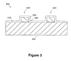
- an exemplary grating structure 300 that may used as a test structure on the wafer 205 is shown.
- the grating structure 300 has the same general construction (e.g ., geometry, materials, pitch, etc. ) as features included in the production devices formed on the wafer 205.
- a process layer 310 is formed over the grating structure 300.
- the grating structure 300 include stacks 320 formed on a substrate 330.
- the stacks 320 include a gate insulation layer 340 and a polysilicon gate electrode 350 that are formed by patterning the same process layers used to form the gate electrodes of actual transistors in the devices on the wafer 205.
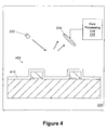
- the scatterometry tool 220 loaded with a wafer 205 having a grating structure 400 and a process layer 410 overlying the grating structure is provided.
- the grating structure 400 may be a feature formed in a production device on the wafer 205 ( i.e., STI structures are not shown in Figure 4 ), or alternatively, the grating structure 400 may be a test structure similar to the grating structure 300 discussed above in reference to Figure 3 .
- the scatterometry tool 220 includes a light source 222 and a detector 224 positioned proximate the grating structure 400 and process layer 410.
- the light source 222 of the scatterometry tool 220 illuminates at least a portion of the process layer 410 overlying the grating structure 400, and the detector 224 takes optical measurements, such as intensity or phase, of the reflected light.
- a data processing unit 225 receives the optical measurements from the detector 224 and processes the data to determine the conformality of the process layer 300.
- the scatterometry tool 220 may use monochromatic light, white light, or some other wavelength or combinations of wavelengths, depending on the specific implementation.
- the angle of incidence of the light may also vary, depending on the specific implementation.
- the light analyzed by the scatterometry tool 220 typically includes a reflected component (i.e ., incident angle equals reflected angle) and a refracted component (i.e ., incident angle does not equal the reflected angle).
- reflected is meant to encompass both components.
- Variations in the conformality of the process layer 410 causes changes in the reflection profile (e.g ., intensity vs. wavelength - tan( ⁇ ), phase vs. wavelength - sin( ⁇ ), where ⁇ and ⁇ are common scatterometry outputs known to those of ordinary skill in the art) measured by the scatterometry tool 220 as compared to the light scattering profile that would be present in a completely conformal process layer 410, or at least a process layer 410 having an acceptable conformality.
- the reflection profile e.g ., intensity vs. wavelength - tan( ⁇ ), phase vs. wavelength - sin( ⁇ )
- Figures 5A, 5B, and 5C illustrate exemplary reflection profiles 500, 510, 520 that may be included in a reference reflection profile library 232 (see Figure 2 ) used by the data processing unit 225 to characterize the conformality of the process layer 410 based on the measured reflection profiles.
- the particular reflection profile expected for any structure depends on the specific geometry of the grating structure 400, the conformality of the process layer 410, and the parameters of the measurement technique employed by the scatterometry tool 220 ( e.g ., light bandwidth, angle of incidence, etc .).
- the profiles in the reference reflection profile library 232 are typically calculated theoretically by employing Maxwell's equations based on the characteristics of the process layer 410 and the topology and geometry of the grating structure 400.
- the profiles in the reference reflection profile library 232 may also be generated empirically by measuring reflection profiles of sample wafers and subsequently characterizing conformality of the measured wafers by destructive or nondestructive examination techniques.
- the reflection profile 500 of Figure 5A represents an expected profile for a process layer 410 with essentially perfect conformality (i.e., equal sidewall and flat surface thicknesses).
- the reflection profile 510 of Figure 5B represents an expected profile for a process layer 410 that has a slightly reduced sidewall thickness ( i.e. , lower conformality), and reflection profile 520 of Figure 5C represents an expected profile for a process layer 410 that has a significant reduction in conformality.
- the reflection profiles of process layers 410 with varying conformality values may be included in the reference reflection profile library 232.
- the data processing unit 225 compares the measured reflection profile to the reference reflection profile library 232.
- Each reference profile has an associated conformality metric, which may be represented by separate sidewall and flat surface actual thicknesses or by the ratio between sidewall thickness and flat surface thickness, for example.
- the data processing unit 225 determines the reference reflection profile having the closest match to the measured reflection profile. Techniques for matching the measured reflection profile to the closest reference reflection profile are well known to those of ordinary skill in the art, so they are not described in greater detail herein.
- the process controller 230 or other external controller may be adapted to compare the measured reflection profile tb the reference reflection profile library 232.
- the scatterometry tool 220 would output the matching reference reflection profile, and the process controller 230 may link that reference reflection profile to an associated conformality metric.
- the measured reflection profile may be compared to a target reflection profile selected from the reference reflection profile library 232 for a process layer 410 having a known and desired conformality characteristic (e.g ., conformality of 1).
- a target reflection profile may be calculated for a process layer 410 having an ideal or acceptable conformality profile using Maxwell's equations, and that target reflection profile may be stored in the reference reflection profile library 232.
- the measured reflection profile of a process layer 410 having an unknown degree of conformality is compared to the target reflection profile. Based upon this comparison, a relatively rough approximation of the conformality may be determined.
- conformality of the process layer 410 may be approximated, such that further matching of the measured reflection profile with additional reference reflection profiles from the reference reflection profile library 232 is unwarranted.
- an initial determination may be made as to the conformality of the process layer 410.
- this step may be performed in addition to the matching or correlating of a measured reflection profile to a reference reflection profile from the reference reflection profile library 232 as described above.
- the process controller 230 may take a variety of autonomous actions.
- the process controller 230 is adapted to modify the operating recipe of the deposition tool 210 based on the conformality metric to control deposition operations on subsequent wafers processed by the deposition tool 210.
- the process controller 230 is adapted to modify the operating recipe of the etch tool 240 to control the etching of the process layer 410 based on the conformality metric.
- both embodiments may be combined and the process controller 230 may control the operating recipes of both the deposition tool 210 and the etch tool 240 simultaneously.
- Various operating recipe parameters of the deposition tool 210 may be controlled to affect the conformality of the deposited process layer 410.
- recipe parameters that affect conformality are the RF-bias of the plasma generator, the pressure under which the deposition process is conducted, and the time and temperature used to normalize the wafer 205 prior to deposition (i.e ., commonly referred to as soak time and soak temperature).
- the process controller 230 may use a control model of the deposition tool 210 for changing its operating recipe.
- the process controller 230 may use a control model relating the measured conformality to a particular operating recipe parameter in the deposition tool 210 to control the RF bias, pressure, or soak parameters to correct for conformality deviations.
- the control model may be developed empirically using commonly known linear or non-linear techniques.
- the control model may be a relatively simple equation based model (e.g., linear, exponential, weighted average, etc .) or a more complex model, such as a neural network model, principal component analysis (PCA) model, or a projection to latent structures (PLS) model.
- PCA principal component analysis
- PLS projection to latent structures
- a conformality model may be generated by the process controller 230, or alternatively, it may be generated by a different processing resource (not shown) and stored on the process controller 230 after being developed.
- the conformality model may be developed using the deposition tool 210 or using a different tool (not shown) having similar operating characteristics. For purposes of illustration, it is assumed that the conformality model is generated and updated by the process controller 230 or other processing resource based on the actual performance of the deposition tool 210 as measured by the scatterometry tool 220.
- the conformality model may be trained based on historical data collected from numerous processing runs of the deposition tool 210.
- the process controller 230 may modify the operating recipe of the etch tool 240 to control subsequent etch processes.
- the width of a spacer formed around a gate electrode is determined to a large extant by the sidewall thickness of the process layer 410.
- the post-etch spacer width can also be controlled by controlling the etch time of the etch tool 240. For example, if the sidewall thickness of the process layer 410 is thicker than a desired target spacer width, the etch process can be continued for a period of time after the silicon substrate has been exposed to reduce the spacer width such that it is closer to the target spacer width.
- a spacer width model may be generated to control the etch time of the etch tool 240 based on the conformality measurement.
- the spacer etch model may be a simple, equation-based control model or a more advanced predictive model, as described above.
- the process controller 230 may access previously stored metrology information regarding the profile of the underlying grating structure 400 prior to formation of the process layer 410 for use in determining the conformality of the process layer 410.
- the profile of the grating structure 400 may have an effect on the apparent conformality. If the profile of the grating structure 400 is re-entrant, it may appear that the sidewall thickness is less than actual. Likewise, if the profile of the grating structure 400 is positive, the sidewall thickness may appear greater than actual. By factoring in the profile of the grating structure 400, the process controller 230 may correct the conformality measurement.
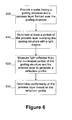
- a simplified flow diagram of a method for determining conformality in a process layer in accordance with another illustrative embodiment of the present invention is provided.
- a wafer having a grating structure 400 and a process layer 410 formed over the grating structure 400 is provided.
- at least a portion of the process layer 410 overlying the grating structure 400 is illuminated with a light source.
- light reflected from the illuminated portion of the grating structure 400 and process layer 410 is measured to generate a reflection profile.
- the conformality of the process layer 410 is determined based on the reflection profile.
- the deposition tool 210 may be controlled to increase the conformality of the process layer 410.
- the etch tool 240 may be controlled to reduce the post etch spacer width variation. Decreased variation increases both the quality of the devices produced on the processing line 200 and the efficiency of the processing line 200.
Landscapes
- General Physics & Mathematics (AREA)
- Analytical Chemistry (AREA)
- Pathology (AREA)
- Immunology (AREA)
- Engineering & Computer Science (AREA)
- Physics & Mathematics (AREA)
- Health & Medical Sciences (AREA)
- Life Sciences & Earth Sciences (AREA)
- General Health & Medical Sciences (AREA)
- Biochemistry (AREA)
- Chemical & Material Sciences (AREA)
- Manufacturing & Machinery (AREA)
- Power Engineering (AREA)
- Microelectronics & Electronic Packaging (AREA)
- Computer Hardware Design (AREA)
- Testing Or Measuring Of Semiconductors Or The Like (AREA)
- Length Measuring Devices By Optical Means (AREA)
Applications Claiming Priority (3)
| Application Number | Priority Date | Filing Date | Title |
|---|---|---|---|
| US865286 | 1997-05-29 | ||
| US09/865,286 US6479309B1 (en) | 2001-05-25 | 2001-05-25 | Method and apparatus for determining process layer conformality |
| PCT/US2002/012827 WO2002097878A2 (en) | 2001-05-25 | 2002-04-02 | Method and apparatus for determining process layer conformality |
Publications (2)
| Publication Number | Publication Date |
|---|---|
| EP1393365A2 EP1393365A2 (en) | 2004-03-03 |
| EP1393365B1 true EP1393365B1 (en) | 2012-01-11 |
Family
ID=25345132
Family Applications (1)
| Application Number | Title | Priority Date | Filing Date |
|---|---|---|---|
| EP02774099A Expired - Lifetime EP1393365B1 (en) | 2001-05-25 | 2002-04-02 | Method for determining process layer conformality |
Country Status (8)
| Country | Link |
|---|---|
| US (1) | US6479309B1 (enExample) |
| EP (1) | EP1393365B1 (enExample) |
| JP (1) | JP4505786B2 (enExample) |
| KR (1) | KR100970492B1 (enExample) |
| CN (1) | CN1254863C (enExample) |
| AU (1) | AU2002307499A1 (enExample) |
| TW (1) | TW557474B (enExample) |
| WO (1) | WO2002097878A2 (enExample) |
Families Citing this family (22)
| Publication number | Priority date | Publication date | Assignee | Title |
|---|---|---|---|---|
| US6639663B1 (en) * | 2001-05-23 | 2003-10-28 | Advanced Micro Devices, Inc. | Method and apparatus for detecting processing faults using scatterometry measurements |
| US6785638B2 (en) * | 2001-08-06 | 2004-08-31 | Timbre Technologies, Inc. | Method and system of dynamic learning through a regression-based library generation process |
| US6660539B1 (en) * | 2001-11-07 | 2003-12-09 | Advanced Micro Devices, Inc. | Methods for dynamically controlling etch endpoint time, and system for accomplishing same |
| US6451621B1 (en) * | 2002-01-16 | 2002-09-17 | Advanced Micro Devices, Inc. | Using scatterometry to measure resist thickness and control implant |
| US6960416B2 (en) * | 2002-03-01 | 2005-11-01 | Applied Materials, Inc. | Method and apparatus for controlling etch processes during fabrication of semiconductor devices |
| US7225047B2 (en) * | 2002-03-19 | 2007-05-29 | Applied Materials, Inc. | Method, system and medium for controlling semiconductor wafer processes using critical dimension measurements |
| US6862545B1 (en) * | 2003-04-03 | 2005-03-01 | Taiwan Semiconductor Manufacturing Co., Ltd | Linewidth measurement tool calibration method employing linewidth standard |
| US6911399B2 (en) * | 2003-09-19 | 2005-06-28 | Applied Materials, Inc. | Method of controlling critical dimension microloading of photoresist trimming process by selective sidewall polymer deposition |
| US7094613B2 (en) * | 2003-10-21 | 2006-08-22 | Applied Materials, Inc. | Method for controlling accuracy and repeatability of an etch process |
| US6980873B2 (en) | 2004-04-23 | 2005-12-27 | Taiwan Semiconductor Manufacturing Company, Ltd. | System and method for real-time fault detection, classification, and correction in a semiconductor manufacturing environment |
| US7437404B2 (en) | 2004-05-20 | 2008-10-14 | Taiwan Semiconductor Manufacturing Company, Ltd. | System and method for improving equipment communication in semiconductor manufacturing equipment |
| US20060154388A1 (en) * | 2005-01-08 | 2006-07-13 | Richard Lewington | Integrated metrology chamber for transparent substrates |
| US7601272B2 (en) * | 2005-01-08 | 2009-10-13 | Applied Materials, Inc. | Method and apparatus for integrating metrology with etch processing |
| DE102005049365A1 (de) | 2005-03-18 | 2006-09-21 | BAM Bundesanstalt für Materialforschung und -prüfung | Kalibriereinrichtung und Farbstoffkit sowie ihre Verwendung zur Charakterisierung von Lumineszenzmesssystemen |
| US7962113B2 (en) * | 2005-10-31 | 2011-06-14 | Silicon Laboratories Inc. | Receiver with multi-tone wideband I/Q mismatch calibration and method therefor |
| US7469164B2 (en) * | 2006-06-26 | 2008-12-23 | Nanometrics Incorporated | Method and apparatus for process control with in-die metrology |
| US20080248598A1 (en) * | 2007-04-09 | 2008-10-09 | Rohit Pal | Method and apparatus for determining characteristics of a stressed material using scatterometry |
| US7663766B2 (en) * | 2007-09-05 | 2010-02-16 | Advanced Micro Devices, Inc. | Incorporating film optical property measurements into scatterometry metrology |
| US7598099B2 (en) * | 2007-11-07 | 2009-10-06 | Tokyo Electron Limited | Method of controlling a fabrication process using an iso-dense bias |
| KR20170138207A (ko) | 2016-06-07 | 2017-12-15 | 삼성전자주식회사 | 표면 검사 방법 |
| US11189614B2 (en) | 2018-03-16 | 2021-11-30 | Intel Corporation | Process etch with reduced loading effect |
| CN112729133B (zh) * | 2020-12-18 | 2023-02-24 | 广东省大湾区集成电路与系统应用研究院 | 一种基于探测光栅衍射强度测量薄膜厚度的方法及装置 |
Family Cites Families (15)
| Publication number | Priority date | Publication date | Assignee | Title |
|---|---|---|---|---|
| US4600597A (en) * | 1984-10-29 | 1986-07-15 | Rca Corporation | Method and device for determining the contour of spin-coated thin films of material on substrate topography |
| US5393624A (en) | 1988-07-29 | 1995-02-28 | Tokyo Electron Limited | Method and apparatus for manufacturing a semiconductor device |
| JP3993888B2 (ja) * | 1993-12-28 | 2007-10-17 | ウォレス ティー.ワイ. タング | 薄膜を監視するための方法および装置 |
| US5880838A (en) | 1996-06-05 | 1999-03-09 | California Institute Of California | System and method for optically measuring a structure |
| JP2970555B2 (ja) * | 1996-10-28 | 1999-11-02 | 日本電気株式会社 | 半導体装置の製造方法及び製造装置 |
| US5867276A (en) | 1997-03-07 | 1999-02-02 | Bio-Rad Laboratories, Inc. | Method for broad wavelength scatterometry |
| JPH10303262A (ja) * | 1997-04-25 | 1998-11-13 | Sony Corp | 多層膜の膜厚測定方法及び測定装置 |
| JPH1180974A (ja) * | 1997-09-03 | 1999-03-26 | Matsushita Electron Corp | エッチング速度測定方法 |
| JP3037922B2 (ja) * | 1997-11-07 | 2000-05-08 | 松下電子工業株式会社 | シリコン含有層の評価方法及びシリサイド層の形成工程の管理方法 |
| JPH11162954A (ja) * | 1997-12-01 | 1999-06-18 | Sony Corp | 光学的手段による薄膜測定方法及び装置並びに成膜装置 |
| JP2000241126A (ja) * | 1999-02-25 | 2000-09-08 | Nikon Corp | 測定装置及び測定方法 |
| US6245584B1 (en) | 1999-07-01 | 2001-06-12 | Advanced Micro Devices | Method for detecting adjustment error in photolithographic stepping printer |
| US6051348A (en) | 1999-08-17 | 2000-04-18 | Advanced Micro Devices | Method for detecting malfunction in photolithographic fabrication track |
| JP2002093871A (ja) | 2000-09-20 | 2002-03-29 | Hitachi Ltd | 半導体製造装置および半導体装置の製造方法 |
| JP2002198410A (ja) | 2000-12-27 | 2002-07-12 | Mitsubishi Electric Corp | 半導体装置の製造方法及び製造システム |
-
2001
- 2001-05-25 US US09/865,286 patent/US6479309B1/en not_active Expired - Fee Related
-
2002
- 2002-04-02 KR KR1020037015073A patent/KR100970492B1/ko not_active Expired - Fee Related
- 2002-04-02 EP EP02774099A patent/EP1393365B1/en not_active Expired - Lifetime
- 2002-04-02 WO PCT/US2002/012827 patent/WO2002097878A2/en not_active Ceased
- 2002-04-02 CN CNB028115279A patent/CN1254863C/zh not_active Expired - Fee Related
- 2002-04-02 AU AU2002307499A patent/AU2002307499A1/en not_active Abandoned
- 2002-04-02 JP JP2003500963A patent/JP4505786B2/ja not_active Expired - Fee Related
- 2002-04-30 TW TW091108912A patent/TW557474B/zh not_active IP Right Cessation
Non-Patent Citations (1)
| Title |
|---|
| RAYMOND C J ET AL: "METROLOGY OF SUBWAVELENGTH PHOTORESIST GRATINGS USING OPTICAL SCATTEROMETRY", JOURNAL OF VACUUM SCIENCE AND TECHNOLOGY: PART B, AVS / AIP, MELVILLE, NEW YORK, NY, US, vol. 13, no. 4, 1 July 1995 (1995-07-01), pages 1484 - 1495, XP000542851, ISSN: 1071-1023, DOI: DOI:10.1116/1.588176 * |
Also Published As
| Publication number | Publication date |
|---|---|
| JP4505786B2 (ja) | 2010-07-21 |
| KR100970492B1 (ko) | 2010-07-16 |
| WO2002097878A3 (en) | 2003-10-16 |
| EP1393365A2 (en) | 2004-03-03 |
| CN1515030A (zh) | 2004-07-21 |
| JP2004528722A (ja) | 2004-09-16 |
| WO2002097878A2 (en) | 2002-12-05 |
| TW557474B (en) | 2003-10-11 |
| US6479309B1 (en) | 2002-11-12 |
| KR20040004632A (ko) | 2004-01-13 |
| CN1254863C (zh) | 2006-05-03 |
| AU2002307499A1 (en) | 2002-12-09 |
Similar Documents
| Publication | Publication Date | Title |
|---|---|---|
| EP1393365B1 (en) | Method for determining process layer conformality | |
| US6383824B1 (en) | Method of using scatterometry measurements to control deposition processes | |
| US7939450B2 (en) | Method and apparatus for spacer-optimization (S-O) | |
| US7456110B2 (en) | Method and apparatus for controlling etch selectivity | |
| US6650423B1 (en) | Method and apparatus for determining column dimensions using scatterometry | |
| US7127358B2 (en) | Method and system for run-to-run control | |
| US6433871B1 (en) | Method of using scatterometry measurements to determine and control gate electrode profiles | |
| US7765077B2 (en) | Method and apparatus for creating a Spacer-Optimization (S-O) library | |
| US20080311688A1 (en) | Method and Apparatus for Creating a Gate Optimization Evaluation Library | |
| US6618149B1 (en) | Method of identifying film stacks based upon optical properties | |
| WO2008157154A1 (en) | Method and apparatus for optimizing a gate channel | |
| US6479200B1 (en) | Method of controlling stepper process parameters based upon scatterometric measurements of DICD features | |
| US8423320B2 (en) | Method and system for quantitative inline material characterization in semiconductor production processes based on structural measurements and related models | |
| US6677170B1 (en) | Method for determining process layer thickness using scatterometry measurements | |
| US7092096B2 (en) | Optical scatterometry method of sidewall spacer analysis | |
| US20020177245A1 (en) | Method and apparatus for controlling feature critical dimensions based on scatterometry derived profile | |
| US6707562B1 (en) | Method of using scatterometry measurements to control photoresist etch process | |
| US6773939B1 (en) | Method and apparatus for determining critical dimension variation in a line structure | |
| US6815235B1 (en) | Methods of controlling formation of metal silicide regions, and system for performing same | |
| US7262864B1 (en) | Method and apparatus for determining grid dimensions using scatterometry | |
| US6562635B1 (en) | Method of controlling metal etch processes, and system for accomplishing same | |
| US20080248598A1 (en) | Method and apparatus for determining characteristics of a stressed material using scatterometry | |
| KR100964001B1 (ko) | 반도체 제조 공정을 제어하기 위한 고수율의 분광 스케테로메트리측정을 사용하는 방법과 이를 구현하는 시스템 | |
| US7663766B2 (en) | Incorporating film optical property measurements into scatterometry metrology | |
| US6804014B1 (en) | Method and apparatus for determining contact opening dimensions using scatterometry |
Legal Events
| Date | Code | Title | Description |
|---|---|---|---|
| PUAI | Public reference made under article 153(3) epc to a published international application that has entered the european phase |
Free format text: ORIGINAL CODE: 0009012 |
|
| 17P | Request for examination filed |
Effective date: 20031126 |
|
| AK | Designated contracting states |
Kind code of ref document: A2 Designated state(s): AT BE CH CY DE DK ES FI FR GB GR IE IT LI LU MC NL PT SE TR |
|
| AX | Request for extension of the european patent |
Extension state: AL LT LV MK RO SI |
|
| RAP1 | Party data changed (applicant data changed or rights of an application transferred) |
Owner name: GLOBALFOUNDRIES, INC. |
|
| 17Q | First examination report despatched |
Effective date: 20110419 |
|
| GRAP | Despatch of communication of intention to grant a patent |
Free format text: ORIGINAL CODE: EPIDOSNIGR1 |
|
| RTI1 | Title (correction) |
Free format text: METHOD FOR DETERMINING PROCESS LAYER CONFORMALITY |
|
| GRAS | Grant fee paid |
Free format text: ORIGINAL CODE: EPIDOSNIGR3 |
|
| GRAA | (expected) grant |
Free format text: ORIGINAL CODE: 0009210 |
|
| AK | Designated contracting states |
Kind code of ref document: B1 Designated state(s): DE GB |
|
| REG | Reference to a national code |
Ref country code: GB Ref legal event code: FG4D |
|
| REG | Reference to a national code |
Ref country code: DE Ref legal event code: R096 Ref document number: 60241972 Country of ref document: DE Effective date: 20120315 |
|
| REG | Reference to a national code |
Ref country code: DE Ref legal event code: R082 Ref document number: 60241972 Country of ref document: DE |
|
| PGFP | Annual fee paid to national office [announced via postgrant information from national office to epo] |
Ref country code: DE Payment date: 20120419 Year of fee payment: 11 |
|
| PLBE | No opposition filed within time limit |
Free format text: ORIGINAL CODE: 0009261 |
|
| STAA | Information on the status of an ep patent application or granted ep patent |
Free format text: STATUS: NO OPPOSITION FILED WITHIN TIME LIMIT |
|
| 26N | No opposition filed |
Effective date: 20121012 |
|
| GBPC | Gb: european patent ceased through non-payment of renewal fee |
Effective date: 20120411 |
|
| PG25 | Lapsed in a contracting state [announced via postgrant information from national office to epo] |
Ref country code: GB Free format text: LAPSE BECAUSE OF NON-PAYMENT OF DUE FEES Effective date: 20120411 |
|
| REG | Reference to a national code |
Ref country code: DE Ref legal event code: R097 Ref document number: 60241972 Country of ref document: DE Effective date: 20121012 |
|
| PG25 | Lapsed in a contracting state [announced via postgrant information from national office to epo] |
Ref country code: DE Free format text: LAPSE BECAUSE OF NON-PAYMENT OF DUE FEES Effective date: 20131101 |
|
| REG | Reference to a national code |
Ref country code: DE Ref legal event code: R119 Ref document number: 60241972 Country of ref document: DE Effective date: 20131101 |