EP1391348A2 - Leuchtkörper-Einsatz zum nachträglichen Einbau in Standard-Fahrzeugseitenspiegel - Google Patents
Leuchtkörper-Einsatz zum nachträglichen Einbau in Standard-Fahrzeugseitenspiegel Download PDFInfo
- Publication number
- EP1391348A2 EP1391348A2 EP03018846A EP03018846A EP1391348A2 EP 1391348 A2 EP1391348 A2 EP 1391348A2 EP 03018846 A EP03018846 A EP 03018846A EP 03018846 A EP03018846 A EP 03018846A EP 1391348 A2 EP1391348 A2 EP 1391348A2
- Authority
- EP
- European Patent Office
- Prior art keywords
- insert
- light
- luminous element
- mirror housing
- luminous
- Prior art date
- Legal status (The legal status is an assumption and is not a legal conclusion. Google has not performed a legal analysis and makes no representation as to the accuracy of the status listed.)
- Withdrawn
Links
- 238000009420 retrofitting Methods 0.000 title claims description 8
- 238000000034 method Methods 0.000 claims abstract description 11
- 239000004020 conductor Substances 0.000 claims description 13
- 229920003023 plastic Polymers 0.000 claims description 11
- 238000007789 sealing Methods 0.000 claims description 4
- 238000003801 milling Methods 0.000 claims description 2
- 230000007704 transition Effects 0.000 claims 1
- 238000004519 manufacturing process Methods 0.000 abstract description 6
- 238000003780 insertion Methods 0.000 abstract 1
- 230000037431 insertion Effects 0.000 abstract 1
- 239000011521 glass Substances 0.000 description 8
- 239000010410 layer Substances 0.000 description 8
- 239000004033 plastic Substances 0.000 description 7
- 238000009434 installation Methods 0.000 description 6
- 230000005855 radiation Effects 0.000 description 6
- XLYOFNOQVPJJNP-UHFFFAOYSA-N water Substances O XLYOFNOQVPJJNP-UHFFFAOYSA-N 0.000 description 5
- 230000004397 blinking Effects 0.000 description 4
- 238000011161 development Methods 0.000 description 4
- 230000018109 developmental process Effects 0.000 description 4
- 239000000463 material Substances 0.000 description 4
- 230000008569 process Effects 0.000 description 4
- 238000004026 adhesive bonding Methods 0.000 description 3
- VVQNEPGJFQJSBK-UHFFFAOYSA-N Methyl methacrylate Chemical compound COC(=O)C(C)=C VVQNEPGJFQJSBK-UHFFFAOYSA-N 0.000 description 2
- 229920005372 Plexiglas® Polymers 0.000 description 2
- 239000000853 adhesive Substances 0.000 description 2
- 230000001070 adhesive effect Effects 0.000 description 2
- 238000004873 anchoring Methods 0.000 description 2
- 239000011248 coating agent Substances 0.000 description 2
- 238000000576 coating method Methods 0.000 description 2
- 230000000694 effects Effects 0.000 description 2
- 230000003760 hair shine Effects 0.000 description 2
- 238000010438 heat treatment Methods 0.000 description 2
- 239000004922 lacquer Substances 0.000 description 2
- 230000007246 mechanism Effects 0.000 description 2
- 239000004417 polycarbonate Substances 0.000 description 2
- 229920000515 polycarbonate Polymers 0.000 description 2
- 239000004575 stone Substances 0.000 description 2
- 229920003002 synthetic resin Polymers 0.000 description 2
- 239000000057 synthetic resin Substances 0.000 description 2
- PAYROHWFGZADBR-UHFFFAOYSA-N 2-[[4-amino-5-(5-iodo-4-methoxy-2-propan-2-ylphenoxy)pyrimidin-2-yl]amino]propane-1,3-diol Chemical compound C1=C(I)C(OC)=CC(C(C)C)=C1OC1=CN=C(NC(CO)CO)N=C1N PAYROHWFGZADBR-UHFFFAOYSA-N 0.000 description 1
- 230000000712 assembly Effects 0.000 description 1
- 238000000429 assembly Methods 0.000 description 1
- 230000008901 benefit Effects 0.000 description 1
- 239000012876 carrier material Substances 0.000 description 1
- 230000008859 change Effects 0.000 description 1
- 238000006243 chemical reaction Methods 0.000 description 1
- 239000011247 coating layer Substances 0.000 description 1
- 150000001875 compounds Chemical class 0.000 description 1
- 238000010276 construction Methods 0.000 description 1
- 230000006735 deficit Effects 0.000 description 1
- 238000009429 electrical wiring Methods 0.000 description 1
- -1 for example Polymers 0.000 description 1
- 230000001771 impaired effect Effects 0.000 description 1
- 238000001746 injection moulding Methods 0.000 description 1
- 210000001503 joint Anatomy 0.000 description 1
- 238000000465 moulding Methods 0.000 description 1
- 230000003287 optical effect Effects 0.000 description 1
- 239000013307 optical fiber Substances 0.000 description 1
- 238000010422 painting Methods 0.000 description 1
- 230000035515 penetration Effects 0.000 description 1
- 238000004382 potting Methods 0.000 description 1
- 230000009467 reduction Effects 0.000 description 1
- 239000000565 sealant Substances 0.000 description 1
- 239000003566 sealing material Substances 0.000 description 1
- 230000035939 shock Effects 0.000 description 1
- 230000009131 signaling function Effects 0.000 description 1
- 238000003860 storage Methods 0.000 description 1
- 239000000725 suspension Substances 0.000 description 1
Images


Classifications
-
- B—PERFORMING OPERATIONS; TRANSPORTING
- B60—VEHICLES IN GENERAL
- B60Q—ARRANGEMENT OF SIGNALLING OR LIGHTING DEVICES, THE MOUNTING OR SUPPORTING THEREOF OR CIRCUITS THEREFOR, FOR VEHICLES IN GENERAL
- B60Q1/00—Arrangement of optical signalling or lighting devices, the mounting or supporting thereof or circuits therefor
- B60Q1/26—Arrangement of optical signalling or lighting devices, the mounting or supporting thereof or circuits therefor the devices being primarily intended to indicate the vehicle, or parts thereof, or to give signals, to other traffic
- B60Q1/2661—Arrangement of optical signalling or lighting devices, the mounting or supporting thereof or circuits therefor the devices being primarily intended to indicate the vehicle, or parts thereof, or to give signals, to other traffic mounted on parts having other functions
- B60Q1/2665—Arrangement of optical signalling or lighting devices, the mounting or supporting thereof or circuits therefor the devices being primarily intended to indicate the vehicle, or parts thereof, or to give signals, to other traffic mounted on parts having other functions on rear-view mirrors
-
- B—PERFORMING OPERATIONS; TRANSPORTING
- B60—VEHICLES IN GENERAL
- B60R—VEHICLES, VEHICLE FITTINGS, OR VEHICLE PARTS, NOT OTHERWISE PROVIDED FOR
- B60R1/00—Optical viewing arrangements; Real-time viewing arrangements for drivers or passengers using optical image capturing systems, e.g. cameras or video systems specially adapted for use in or on vehicles
- B60R1/12—Mirror assemblies combined with other articles, e.g. clocks
- B60R1/1207—Mirror assemblies combined with other articles, e.g. clocks with lamps; with turn indicators
Definitions
- the invention relates to a filament insert for retrofitting in standard vehicle side mirrors and a kit for it.
- Indicator lights integrated in the side mirrors equip in order to make the turn or Improve lane change or warning signals.
- exemplary may be mentioned in English GB 2 266 870 A.
- EP 997 346 A1 a side mirror turn signal unit in which in the housing of the unit on the side facing away from the vehicle separate light sources on the one hand in front of the vehicle radiate area and on the other hand in the against the direction of travel by up to 60 ° to the outside inclined angular range.
- the light of the opposite The direction indicator, which shines in the direction of travel, is an ellipsoidal reflector in the desired Angular range steered.
- the side mirrors shown in the cited documents are intended for the original equipment of cars.
- the Side mirrors therefore each have specially designed Side mirror housing in which more or less complicated, consisting of several individual parts Blinker signal arrangements are installed.
- Different expressed, the turn signal assemblies shown there each require a specially adapted mirror housing.
- According to the invention is also a separate unit executed lamp insert provided in existing vehicle side mirrors can be installed.
- the insert closes the housing recess to the outside down. Even if there is a gap between use and Housing can be tolerated because existing mirrors are not completely watertight sealed Cutout preferably completely sealed.
- the lamp insert is in one piece and as Full body design and is therefore robust and light manageable in construction and installation.
- the luminous insert can be almost complete, i.e. until Illuminant and light seal towards the interior, off transparent plastic.
- the use according to the invention advantageously has Front end with an increase pointing in the direction of travel which he projects into the interior of the mirror housing. So it says there Installation space available to use an illuminant take.
- the illuminant shines through the Body of the insert into the desired one Beam area that is directed sideways to the rear.
- the turn signal is also off oncoming road users perceptible.
- the built-in lamp insert has an advantage Condition also on its side facing the rear of the vehicle an increase at which the filament insert from the Side mirror housing emerges from one to the rear of the vehicle exposing pointing light surface. Only on the Raises, softens the shape of the mirror housing insert used from the standard outer contour from. Otherwise the filament insert fits seamlessly into the standard turn signal housing or completes this volume outwards and closes it to the outside. So they stay aerodynamic properties of a mass-produced Standard mirror housing largely preserved. Also the The stability of the mirror housing is not affected.
- the shape, the geometry and the Installation position of the filament insert not specific limited. It will depend on the shape of the Mirror, its orientation to the vehicle and the desired security effect to be achieved. If the outer contour of the mirror housing transverse to Longitudinal vehicle is convex, can Luminaire insert even one with the outer contour of the Standard vehicle side mirror flush outer surface and still have one against the vehicle's longitudinal axis trained pointing surface and into the mirror housing is inserted in one place, on the filament insert can
- the lamp insert completes the mirror housing in terms of volume. In the area of the increase at which the Luminaire insert from the side mirror housing emerges, there is thus space available for a Record bulbs.
- the filament insert with at least one light emitting diode (LED) as Illuminant and a support with a light-guiding Layer of light-conducting material, preferably transparent plastic to equip.
- LED light emitting diode
- the LED is preferably behind the Luminous surface arranged in a recess in the carrier.
- the filament insert makes it possible in an advantageous manner, the filament insert a to give slim shape so that it fits ideally into that Inserts mirror housing without too much space in the To stress the interior of the housing. LEDs generate over it only low heat loss and therefore have a long life, making the diode maintenance-free fixed can be installed without a subsequent It must be possible to replace the diode.
- a seal is provided which the Recess in which the LED sits against the Inside the mirror housing, i.e. the side facing the driver, seals.
- the seal is advantageously reflective, so that the entire radiation is in the desired direction is directed.
- the reflective seal can be done as a single Reflector component can be provided. In the case of several Light-emitting diodes can also be provided with several reflectors his. Alternatively or in addition, a reflective layer on the inside of the Mirror housing facing surface are applied. Lacquers, vapor-deposited or are suitable for this sprayed layers.
- the LED together with yours is advantageous electrical connection sealed into the recess.
- the Sealing can be done by potting with plastic, for example, synthetic resin. That way ensures that even if filament unit and The mirror housing should not lie against each other in a watertight manner entire electrics of the filament insert hermetically sealed is isolated from all external influences. Also a certain protection against external mechanical influences (e.g. Shocks) is given, so that the Luminaire insert both in storage and when Transport as well as when installed as robust against Shows damage.
- gluing the lamp insert in the Butt joint conceivable.
- Luminaire insert parallel to the inner contour of the Mirror housing flanges provided on the Luminous element insert can be glued into the housing. It can a circumferential flange can also be provided.
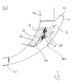
- the standard side mirror shown roughly schematically in FIG. 1 2 can via a housing bracket 16, which on Mirror base is arranged to be attached to a car.
- the interior of the housing for receiving the (not shown) Mirror glass, an adjustment mechanism or electronics etc. is on the side facing the driver from the Limited mirror glass.
- On the in the direction of travel facing side arches a housing 30 in the form of a closed half-shell made of plastic the interior around, along with one at the opposite web 40 adjoining the direction of travel delimited a recess 10.
- the surface of the Housing shell 30 is approximated to a streamlined body, i.e. as approximately semi-elliptical or parabolic Freeform surface held without edges.
- the side mirror 2 receives a slippery shape bulbous design, so that one inside for installation an additional indicator light insert is sufficient Space is available.
- the of the housing shell 30 and the web 40th included recess 10 was from the housing shell 30 milled out and corresponds to the contour of the in Fig. 2nd Bink lamp insert 1 shown in a highly schematic manner.
- the turn signal insert 1 the shape predetermined by the housing shell 30 such that the piece milled out at the recess 10 the housing shell 30 through the turn signal insert 1 is replaced, the outer surface of the mirror housing before milling and the outer surface after Installation of the turn signal lamp insert 1 essentially are congruent.
- the recess 10 is on all sides from the housing shell 30 and the web 40, the part of Housing shell 30 is enclosed, the one used Direction indicator insert 1 after installing the side mirror 2 the housing shell 30 completed in volume Recess 10 and closes to the outside.
- the turn signal insert 1 has a thickness of Housing shell 30 outgoing thickness, which differs from that End facing the vehicle from flowing to one Increase 12 widened towards the rear of the vehicle pointing end reaches its greatest width. Within the Indicator insert 1 is therefore space for Light source (s) and electrical system available. At the same time with the side surface of the elevation facing the rear of the vehicle 12 created a luminous surface 14 through which light in the desired angle range of 5 - 60 ° to the transverse axis of the Vehicle in the direction facing the rear of the vehicle can leak.
- the Fixing the turn signal lamp insert 1 by gluing but also other cohesive or form-fitting ones Processes such as snap, clip or Remote nose closures, springs to be hung, etc., could be used for this.
- the turn signal lamp insert is embodied on all sides enclosed by the housing 130.
- Rear side (against the Direction of travel F) the turn signal insert 100; 200 thus from behind the turn signal insert 100; 200 bordered wall section of the mirror housing 130, which as an additional light shield for the Vehicle driver acts, which therefore also by stray light is not distracted from the traffic.
- the blinker insert 100 equipped with two light emitting diodes 20, each in a bore 118 sit, which from the inside of the Bet 100, i.e. the in the installed state for Side facing the inside of the housing, from diagonally to the rear run and the light emitted by the LEDs lead to the rear light surface 14 or 114.
- the luminous area 14 is one Embodiment of the invention located in which the Illuminated surface 14 is approximately at 90 ° to the direction of travel running, flat surface. But is preferred a nose 13 on the rear of the turn signal lamp insert 100 provided, the one drawn with a solid line Surface 114 forms the luminous surface 114.
- two LEDs are used, depending on the power of the LEDs but also the use of only one or more LEDs conceivable.
- blinking signal-colored LEDs come on used, but it would also be possible to use a different color to use luminous LEDs and the light emission by correspondingly arranged color filters in turn signal orange to color.
- the LEDs 20 are on the inside of the insert 100 inserted into the holes 118 and there in a Plastic compound 128 poured in and thus stable in position attached. Via a conductor strip 24 which is connected to the LEDs 20 is connected, the power supply takes place.
- the Conductor strip 24 does not have suitable ones on the vehicle side shown connections with which it is possible when installing the Filament insert 100 with the vehicle electrical system too connect is.
- the conductor strip 24 through the Mirror housing foot and the vehicle door with the To connect the blinker.
- the conductor strip 24 it is sufficient to have the conductor strip 24 with it to provide a suitable connector and up to Connection point.
- the conductor strip is preferred glued to the inside of the mirror housing, all the more so To ensure position stability. If you already have one electrical wiring is present, for example one electric motor in the housing for mirror adjustment, could also replace the existing wiring with A conductor strip 24 may be provided, which in addition to the wires Turn signal control cores and connections for controlling the Has mirror adjustment or heating mechanisms.
- the inside is of the turn signal insert 100 further with a reflective coating layer 126 coated, whereby a Reliable light emission in the direction of the driver's cabin is prevented and all light to the outside is reflected.
- a light emission thus takes place in Direction of travel F as well as sideways outwards and at an angle to the rear (against the direction of travel F).
- the structure of the Direction indicator 100 which is an inexpensive and in Mass production feasible manufacture of the turn signal insert 100 allowed: After a first step of Pouring, injection molding or otherwise molding the Body of the turn signal insert from a suitable, possibly translucent plastic, for example Polycarbonate or plexiglass (PMMA), in a second Step diode receiving holes 118 are drilled in, the diode mounting holes 118 are equipped with LEDs and wired to a conductor tape 24. In one subsequent step are the diodes with their electrical connections then watertight and stable cast their positions in the insert or through Application of a sealing layer 128 sealed. Finally, the reflection layer 126 is applied to the Sealing layer 128 sprayed, evaporated or otherwise applied.
- a suitable, possibly translucent plastic for example Polycarbonate or plexiglass (PMMA)
- the diode mounting holes 118 are equipped with LEDs and wired to a conductor tape 24.
- the diodes with their electrical connections then watertight and stable cast their positions in the insert or through Application of a sealing layer 128
- the installation of the turn signal lamp insert 100 is therefore possible also easy because the insert is in one piece is built up and thus only a part in the The recess provided in the mirror housing is inserted and provided on the turn signal insert 100 Anchoring elements is attached to the mirror housing 130.
- the wiring (conductor strip 24) is up to the appropriate Connection point to the vehicle electrical system.
- the wiring (strip 24), but also the shape and the fastening elements intended for use 100 are each in the series of the vehicle, or the Adjusted side mirror.
- Suitable as anchoring elements especially resilient lugs, clips, clips or Tension springs.
- the turn signal insert 200 shown in FIG. 5 according to a further embodiment of the invention for the most part the same design as the one in the Figures 3 and 4 shown, two LEDs 24 in provided receptacles 218 are arranged, which in Direction obliquely from the inside of the insert run towards the rear of the vehicle. On that one Luminous surface 114, which surrounds a nose 13, can do this radiated light in the desired angular range be broadcast. Deviating from the embodiment of the Figures 3 and 4 is on the inside behind the Light-emitting diodes 24, however, are designed as individual parts Reflector 22, in the same time holders for the LEDs 24 are provided.
- the reflector 22 is located in a further recess 218a, which in turn with Sealant 228 is poured out, making the reflector and so that the LEDs are firmly anchored in position. Also at In this embodiment of the invention, the LEDs 24 are included their electrical connections in the turn signal insert 200 thus hermetically against external interference such as Splashed water or stone chips.
- the Reflector becomes the main part of the light emitted in those lying laterally against the direction of travel F. Angular range directed behind the luminous surface F. A part the scattered light is also in the direction of travel broadcast so that the blinking signal also from oncoming road users are perceived can.
- the turn signal insert 200 shown in FIG. 5 leaves thus essentially the same Manufacturing process like that in Figures 3 and 4 Manufacture blinker insert 100 shown. Instead of that Insert the individual LEDs in the designated ones
- the embodiment of the invention shown in FIG. 6 there is an additional LED radiating in the direction of travel 21 in a corresponding additional mounting hole 319, so that it also faces in the direction of travel F. Light emission takes place.
- the receiving bore 319 is in the wall of the receptacle facing the direction of travel F. 318a drilled while in the rear wall of the Recording 318a two with opposite to the direction of travel emitting LEDs 20 equipped mounting holes 318 are drilled in.
- a Signal radiation in the direction of travel even when as Pouring compound 328 an opaque or strong reflective material is used that the Light emission from the two light emitting diodes 20 in the opposite direction area in the direction of travel.
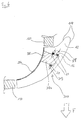
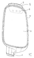
- FIG. 7 At 30 is a standard side mirror housing of the vehicle side mirror referred to that via a housing bracket 16, or a suspension 16 is attached to the vehicle and surrounds a mirror glass 50.
- a luminous element insert 400 On the of the housing bracket 16 opposite side of the mirror housing 30 (outside) a luminous element insert 400 can be seen, which with a luminous area 414 over the outer contour of the Mirror housing 400 protrudes and the top down curved course of the outer contour of the mirror housing 400 follows.
- the position of the Filament insert 400 on the back of the Side mirror indicated.
- the housing of the standard side mirror is as a continuous half-shell designed.
- the filament insert 400 is closer shown.
- the filament insert 400 is in the essentially bowl-shaped.
- On the mirror glass 50 At the end facing the rear of the vehicle is an adhesive flange 425 in front and at its end facing the vehicle front a projection or nose 419.
- Projection 419 can be the lamp insert 400 with the Inner contour of the mirror housing 30 are glued.
- a circuit board 435 is inserted.
- the circuit board is supported on a shoulder Opening 418 off.
- the LEDs 420 would be glued or the circuit board 435 in the opening 418 possible.
- the opening 418 with a sealing material 437, for example synthetic resin, waterproof sealed or been poured out.
- a connecting line 424 for the LEDs 420 is from the Body 419 led out and on the inner contour of the Housing 30 relocated, preferably glued. Also a rear connector, as designated in Fig. 10 with 439, would be conceivable.
- the wiring 424 can be on the vehicle side have suitable connections, not shown, with which it when installing the filament insert 400 with the Vehicle electrics can be connected. Depending on the type of vehicle can be provided, for example, the conductor strip 424 through the mirror housing base and the vehicle door to connect the flasher or one previously dead Use the connection in the mirror housing for this.
- the light conduction from the LEDs 420 to the luminous area 414 takes over a light-guiding body 429 of the Luminous element insert 400, which if possible from a transparent plastic, for example polycarbonate or Plexiglass (PMMA) is poured.
- a transparent plastic for example polycarbonate or Plexiglass (PMMA) is poured.
- PMMA Plexiglass
- the inside of the light guiding body 429 becomes thereby over its entire length by a reflector part 431 shielded against the interior of the housing.
- the reflector part 431 can, for example, consist of a black plastic, which on the to chrome-plated light-guiding body 429, is preferably steamed.
- the reflector part 431 and the light-guiding bodies 429 are only in the area of the flange 425 and the projection 419.
- the light guiding body 429 with the drilled Opening 418, the LED circuit board unit 420, 435 and that Reflector part 431 are prefabricated and then assembled into a one-piece unit and waterproof or glued.
- a luminous element insert 400 is thus created, which is robust against stone chips and splash water and one good light emission in the desired angular range (a against the vehicle's longitudinal axis against the direction of travel 30 - 85 ° outward inclined angular range) guaranteed.
- Such an effect can also be increased Refractive index or reflectance on the outer surface in the front area of the outer contour of the insert 400 be achieved.
- FIG. 5 shows a luminous element insert 500, which completes the housing shell 30 by volume and at an elevation 517 on its in the direction of travel F projecting end protrudes inwards. At the increase 517 connects a nose 519, in which the light-emitting diode 520 is recorded and sealed. Despite the lack of one end elevation, or a counter to the direction of travel Pointing luminous area, the light can be in the desired Angular range can be emitted. Inside is the Luminous body insert 500 with a reflective layer 528 steamed.
- the Inner surface of the turn signal insert is opaque, to be coated or reflective.
- Embodiments could be achieved through an additional, at least partially applied mirroring of the images 218a; 318a, for example in the form of a lacquer layer, a additional focusing of the light radiation in the desired direction.
- FIGS. 7 to 10 Design the attachment of the turn signal insert 400 in the mirror housing 30 by gluing.
- other cohesive or but positive procedures are used, such as for example with snap, clip or spring nose closures, springs to be hung etc.
Landscapes
- Engineering & Computer Science (AREA)
- Mechanical Engineering (AREA)
- Multimedia (AREA)
- Lighting Device Outwards From Vehicle And Optical Signal (AREA)
Abstract
Description
Claims (31)
- Leuchtkörper-Einsatz (1; 100; 200; 300; 400; 500) zum nachträglichen Einbau in serienmäßige Standard-Fahrzeugseitenspiegel (2), der als Vollkörper ein Spiegelgehäuse (30; 130) eines Fahrzeugseitenspiegels (2) volumenmäßig vervollständigt und zur Außenseite hin abschließt, in der Form einer einstückigen Schale, die formschlüssig in eine nachträglich in einen durchgehenden Wandabschnitt des Spiegelgehäuses (30; 130) eingebrachte Aussparung (10; 410; 510) einsetzbar ist, und zumindest ein Leuchtmittel (20; 420; 520) aufweist.
- Leuchtkörper-Einsatz (1; 100; 200; 300; 400) nach Anspruch 1, dadurch gekennzeichnet, dass
die Schale zu einer einer Gehäusehalterung (16) abgewandten Seite hin von der Außenkontur des Standard-Fahrzeugseitenspiegels (2) zunehmend vorspringt, so dass sie mit ihrer endseitigen Erhöhung (12; 412) eine im wesentlichen entgegen der Fahrtrichtung weisende Leuchtfläche (14; 114; 414) ausbildet. - Leuchtkörper-Einsatz (400; 500) nach Anspruch 1 oder 2, dadurch gekennzeichnet, dass die Schale zu einer einer Gehäusehalterung (16) zugewandten Seite hin von der Innenkontur des Spiegelgehäuses (30) zunehmend vorspringt und eine anfangsseitige Erhöhung (417; 517) bildet, in der das Leuchtmittel (420; 520) aufgenommen ist.
- Leuchtkörper-Einsatz nach Anspruch 1 oder 3, dadurch gekennzeichnet, dass der Leuchtkörper-Einsatz eine mit der Außenkontur des Standard-Fahrzeugseitenspiegels (2) bündige Außenoberfläche hat und in das Spiegelgehäuse an einer Stelle eingesetzt ist, an die Außenkontur des Spiegelgehäuses (30) quer zur Fahrzeuglängsache konvex ausgewölbt ist.
- Leuchtkörper-Einsatz (1; 100; 200; 300) nach einem der vorhergehenden Ansprüche, dadurch gekennzeichnet, dass die Leuchtfläche (114) auf einer entgegen der Fahrtrichtung weisenden Nase (13) ausgebildet ist, welche an die Erhöhung (12) anschließt.
- Leuchtkörper-Einsatz (1; 100; 200; 300; 400; 500) nach einem der vorhergehenden Ansprüche, dadurch gekennzeichnet, dass das Leuchtmittel (20; 420; 520), vorzugsweise zumindest eine Leuchtdiode (20; 420; 520), aufweist und einen Träger (129; 229; 429; 529) mit einer lichtführenden Schicht aus lichtleitendem Material, vorzugsweise transparentem Kunststoff, vorgesehen ist.
- Leuchtkörper-Einsatz (1; 100; 200; 300; 400) nach einem der vorhergehenden Ansprüche, dadurch gekennzeichnet, dass hinter der Leuchtfläche (14; 114; 414) zumindest eine Ausnehmung (118; 218, 218a) vorgesehen ist, in der die Leuchtdiode (20; 420) untergebracht ist.
- Leuchtkörper-Einsatz (100; 300; 400; 500) nach einem der vorhergehenden Ansprüche, dadurch gekennzeichnet, dass an der lichtführenden Schicht (12, 13; 429; 529) innenseitig anschließend eine zumindest weitgehend lichtdichte, vorzugsweise reflektierende Abdichtung (126, 128; 326; 431; 528) vorgesehen ist.
- Leuchtkörper-Einsatz (400) nach Anspruch 8, dadurch gekennzeichnet, dass am Übergang zwischen der lichtführenden Schicht (429) und der Abdichtung (431) eine Streuschicht (427) mit einem lichtleitenden Material geringerer Dichte, vorzugsweise Luft, vorgesehen ist.
- Leuchtkörper-Einsatz (400; 500) nach einem der vorhergehenden Ansprüche, dadurch gekennzeichnet, dass an seinem in Fahrtrichtung (F) weisenden Ende ein Flansch (433; 533) parallel zur Innenkontur des Spiegelgehäuses (30) ausgebildet ist, über den der Leuchtkörper-Einsatz (400; 500) mit dem Spiegelgehäuse (30) verbindbar, vorzugsweise verklebbar ist.
- Leuchtkörper-Einsatz (400; 500) nach einem der vorhergehenden Ansprüche, dadurch gekennzeichnet, dass an seinem entgegen der Fahrtrichtung (F) weisenden Ende ein Flansch (425; 525) parallel zur Innenkontur des Spiegelgehäuses (30) ausgebildet ist, über den der Leuchtkörper-Einsatz (400; 500) mit dem Spiegelgehäuse (30) verbindbar, vorzugsweise verklebbar ist.
- Leuchtkörper-Einsatz (400) nach einem der vorhergehenden Ansprüche, dadurch gekennzeichnet, dass die Abdichtung (431) als ein vorzugsweise im Bereich der Flansche (425, 433) mit der lichtführenden Schicht (429) verbundenes, vorzugsweise verklebtes Bauteil (431) vorgesehen ist, welches den Leuchtkörper-Einsatz (400) innenseitig abschließt.
- Leuchtkörper-Einsatz (1; 100; 200; 300; 400; 500) nach einem der vorhergehenden Ansprüche, dadurch gekennzeichnet, dass die elektrische Versorgung der Leuchtdiode (20; 420) über ein Leiterband (24; 424; 524) erfolgt, das mit der Innenseite des Spiegelgehäuses (30; 130) verklebbar ist.
- Leuchtkörper-Einsatz (1; 100; 200; 300) nach einem der vorhergehenden Ansprüche, dadurch gekennzeichnet, dass federnde Nasen vorgesehen sind, über die der Leuchtkörper-Einsatz (1; 100; 200; 300) im Spiegelgehäuse (30; 130) befestigbar ist.
- Leuchtkörper-Einsatz (1; 100; 200; 300) nach einem der Ansprüche 2 bis 14, dadurch gekennzeichnet, dass der Leuchtkörper-Einsatz (1; 100; 200; 300) das Spiegelgehäuse (30; 130) volumenmäßig vervollständigt und die Ausnehmung (118; 218, 218a) mit der Leuchtdiode im Bereich der endseitigen Erhöhung (12) angeordnet ist.
- Leuchtkörper-Einsatz (100; 200; 300) nach Anspruch 15, dadurch gekennzeichnet, dass die Leuchtdiode (20) innenseitig am Leuchtkörper-Einsatz (100; 200; 300) angebracht ist.
- Leuchtkörper-Einsatz (100; 200; 300) nach Anspruch 15 oder 16, dadurch gekennzeichnet, dass der Leuchtkörper-Einsatz (100; 200; 300) auf seiner Innenseite eine die Leuchtdiode (20) und elektrische Anschlüsse in die Ausnehmung (118; 218, 218a; 318) einsiegelnde Schicht (128; 228; 328) aufweist.
- Leuchtkörper-Einsatz (200) nach einem der Ansprüche 15 bis 17, dadurch gekennzeichnet, dass die Leuchtdiode (20) vor einem Reflektor (22) angeordnet ist, der die Ausnehmung (218, 218a) des Leuchtkörper-Einsatzes (200) zur Innenseite der Spiegelgehäuses (130) hin abschließt.
- Leuchtkörper-Einsatz (100; 300) nach einem der Ansprüche 15 bis 18, dadurch gekennzeichnet, dass die dem Innenraum des Spiegelgehäuses (130) zugewandte Oberfläche des Leuchtkörper-Einsatzes (100; 300) mit Ausnahme eines der Leuchtfläche (14; 114) zugewandten Teilbereichs der Ausnehmung mit einer reflektierenden Schicht (126; 326) versehen ist.
- Leuchtkörper-Einsatz (400; 500) nach einem der Ansprüche 3 bis 14, dadurch gekennzeichnet, dass die anfangsseitige Erhöhung (417; 517) eine in Fahrtrichtung (F) vorstehende Nase (419) aufweist, in der das Leuchtmittel (420; 520) eingefasst ist.
- Leuchtkörper-Einsatz (400; 500) nach Anspruch 20, dadurch gekennzeichnet, dass der Flansch (433) parallel zur Innenkontur des Spiegelgehäuses (30) an der in Fahrtrichtung (F) vorstehenden Nase (419) ausgebildet ist.
- Leuchtkörper-Einsatz (400; 500) nach Anspruch 20 oder 21, dadurch gekennzeichnet, dass die Leuchtdiode (420) mit einer Leiterplatte (435) in einer Öffnung in der in Fahrtrichtung (F) vorstehenden Nase (419) eingegossen ist.
- Leuchtkörper-Einsatz (400) nach einem der Ansprüche 3 bis 21, dadurch gekennzeichnet, dass die lichtführende Schicht (429) zumindest abschnittsweise zwischen der anfangsseitigen und der endseitigen Erhöhung (417, 412) eine weitgehend konstante Dicke (DW) aufweist.
- Leuchtkörper-Einsatz (400) nach einem der Ansprüche 3 bis 23, gekennzeichnet durch eine innenseitige Ausnehmung (423) die dem Verlauf der lichtführenden Schicht (429) folgt.
- Bausatz zum Nachrüsten eines serienmäßigen Standard-Fahrzeugseitenspiegels mit einem Blinkleuchtkörper, bestehend aus einem Leuchtkörper-Einsatz (1; 100, 200; 300; 400; 500) nach einem der Ansprüche 1 bis 24 und einem Standard-Seitenspiegelgehäuse (30), an dem eine Ausnehmung (10; 410; 510), vorzugsweise eine Freifräsung, vorgesehen ist, die der Randkontur des Leuchtkörper-Einsatzes (1; 100, 200; 300; 400; 500) mehrseitig folgt.
- Bausatz nach Anspruch 25, dadurch gekennzeichnet, dass der Originalzustand des Standard-Seitenspiegelgehäuses (30) lediglich durch die Ausnehmung (10; 410; 510) verändert ist.
- Verwendung eines Leuchtkörper-Einsatzes (1; 100; 200; 300; 400; 500) nach einem der Ansprüche 1 bis 24 zum Nachrüsten eines serienmäßigen Standard-Fahrzeugseitenspiegels mit einem Blinkleuchtkörper.
- Verwendung eines Bausatzes nach Anspruch 25 oder 26 zum Nachrüsten eines serienmäßigen Standard-Fahrzeugseitenspiegels mit einem Blinkleuchtkörper.
- Verfahren zum Nachrüsten serienmäßiger Seitenspiegel (2) bei gängigen Kfz-Typen, deren Gehäuse (30) nicht von vorne herein zur Aufnahme eines Blinklichts vorgesehen ist, zu Seitenspiegel-Blinker-Einheiten, mit den folgenden Schritten:Einbringen, insbesondere Ausfräsen einer Aussparung (10; 410; 510) in einen durchgehenden Wandabschnitt eines Seitenspiegelgehäuses (30) eines serienmäßigen Standard-Fahrzeugseitenspiegels (2), undEinsetzen und Befestigen eines Leuchtkörper-Einsatzes (1; 100; 200; 300; 400; 500), insbesondere nach einem der Ansprüche 1 bis 13, in der Aussparung (10; 410; 510) .
- Verfahren nach Anspruch 29, dadurch gekennzeichnet, dass das vorhandene Standard-Seitenspiegelgehäuse am Fahrzeug durch das Standard-Seitenspiegelgehäuse (30) mit der eingebrachten Aussparung (10; 410; 510) ersetzt wird.
- Verfahren nach Anspruch 29 oder 30, bei dem der Leuchtkörper-Einsatz (1; 100; 200; 300; 400; 500) anschließend elektrisch angeschlossen wird.
Applications Claiming Priority (4)
| Application Number | Priority Date | Filing Date | Title |
|---|---|---|---|
| DE2002138264 DE10238264B4 (de) | 2002-08-21 | 2002-08-21 | Blinkbeleuchtung für Fahrzeugseitenspiegel |
| DE10238264 | 2002-08-21 | ||
| DE2003136615 DE10336615A1 (de) | 2002-08-21 | 2003-08-08 | Leuchtköper-Einsatz zum nachträglichen Einbau in Standard-Fahrzeugseitenspiegel |
| DE10336615 | 2003-08-08 |
Publications (2)
| Publication Number | Publication Date |
|---|---|
| EP1391348A2 true EP1391348A2 (de) | 2004-02-25 |
| EP1391348A3 EP1391348A3 (de) | 2004-06-16 |
Family
ID=31189308
Family Applications (1)
| Application Number | Title | Priority Date | Filing Date |
|---|---|---|---|
| EP03018846A Withdrawn EP1391348A3 (de) | 2002-08-21 | 2003-08-19 | Leuchtkörper-Einsatz zum nachträglichen Einbau in Standard-Fahrzeugseitenspiegel |
Country Status (2)
| Country | Link |
|---|---|
| EP (1) | EP1391348A3 (de) |
| DE (1) | DE10336615A1 (de) |
Cited By (11)
| Publication number | Priority date | Publication date | Assignee | Title |
|---|---|---|---|---|
| WO2006018067A1 (de) * | 2004-08-11 | 2006-02-23 | Bayerische Motoren Werke Aktiengesellschaft | Kraftfahrzeugleuchte mit einer aus kunststoff gefertigten lichtscheibe |
| DE102004046322A1 (de) * | 2004-09-17 | 2006-04-06 | Magna Reflex Holding Gmbh | Außenrückblickspiegel |
| DE102009019092A1 (de) * | 2009-04-20 | 2010-11-04 | SMR Patents S.à.r.l. | Minimaler LED Blinker im Außenspiegel |
| EP2325046A1 (de) | 2009-11-17 | 2011-05-25 | SMR Patents S.à.r.l. | Verfahren zur Montage eines Blinklichtmoduls und Blinklichtuntermodul |
| EP2377720A1 (de) * | 2010-04-19 | 2011-10-19 | SMR Patents S.à.r.l. | Lichtleitervorrichtung zur Verwendung in Automobilen |
| EP2517931A3 (de) * | 2011-04-08 | 2013-02-20 | Melvin Thomas | Fahrzeugspiegelsystem |
| WO2013075792A3 (de) * | 2011-11-25 | 2013-07-18 | Volkswagen Aktiengesellschaft | Beleuchtungsvorrichtung für ein kraftfahrzeug |
| EP2853444A1 (de) * | 2013-09-26 | 2015-04-01 | Fico Mirrors S.A. | Spiegelvorrichtung für Kraftfahrzeuge und Verfahren zum Zusammenbau derselben |
| US10125943B2 (en) | 2014-03-12 | 2018-11-13 | Volkswagen Aktiengesellschaft | Motor vehicle and motor vehicle headlamp with a front housing |
| EP3138734B1 (de) * | 2015-09-03 | 2020-04-15 | SMR Patents S.à.r.l. | Lichtmodul, lichtanordnung und rückspiegelvorrichtung für ein fahrzeug |
| US11603976B2 (en) | 2021-02-08 | 2023-03-14 | Volkswagen Aktiengesellschaft | Motor vehicle headlamp and method for operating a motor vehicle headlamp |
Families Citing this family (1)
| Publication number | Priority date | Publication date | Assignee | Title |
|---|---|---|---|---|
| DE102005013682B4 (de) * | 2005-03-18 | 2010-07-08 | SMR Patents S.à.r.l. | Außenrückblickspiegel von Fahrzeugen, vorzugsweise von Kraftfahrzeugen |
Citations (1)
| Publication number | Priority date | Publication date | Assignee | Title |
|---|---|---|---|---|
| EP0899503A1 (de) * | 1997-08-22 | 1999-03-03 | Bridgestone Corporation | Lineare Lichtquelle |
Family Cites Families (9)
| Publication number | Priority date | Publication date | Assignee | Title |
|---|---|---|---|---|
| GB2291386A (en) * | 1994-07-15 | 1996-01-24 | Terence John Allsop | Combined mirror and indicator |
| DE29702746U1 (de) * | 1997-02-18 | 1997-04-03 | Reitter & Schefenacker GmbH & Co. KG, 73730 Esslingen | Außenrückblickspiegel für Fahrzeuge, vorzugsweise für Kraftfahrzeuge |
| CA2230930A1 (en) * | 1997-04-25 | 1998-10-25 | Dale Gathergood | Exterior rear view mirror integral warning light |
| DE19843816A1 (de) * | 1998-09-24 | 2000-03-30 | Hella Kg Hueck & Co | Scheinwerfereinheit für Kraftfahrzeuge |
| EP1022187B2 (de) * | 1999-01-21 | 2011-12-07 | Truck-Lite Europe GmbH | Fahrzeugleuchte |
| US6502970B1 (en) * | 1999-06-30 | 2003-01-07 | Federal-Mogus World Wide, Inc. | Vehicular puddle light |
| US6325517B1 (en) * | 2000-02-11 | 2001-12-04 | Su Chang Kuo | Rear vision mirror with cold light direction signal indicator |
| DE20013330U1 (de) * | 2000-08-02 | 2001-01-11 | FER Fahrzeugelektrik GmbH, 99817 Eisenach | Kraftfahrzeugleuchte |
| ES2278670T3 (es) * | 2000-10-04 | 2007-08-16 | Fer Fahrzeugelektrik Gmbh | Luz intermitente lateral. |
-
2003
- 2003-08-08 DE DE2003136615 patent/DE10336615A1/de not_active Withdrawn
- 2003-08-19 EP EP03018846A patent/EP1391348A3/de not_active Withdrawn
Patent Citations (1)
| Publication number | Priority date | Publication date | Assignee | Title |
|---|---|---|---|---|
| EP0899503A1 (de) * | 1997-08-22 | 1999-03-03 | Bridgestone Corporation | Lineare Lichtquelle |
Cited By (22)
| Publication number | Priority date | Publication date | Assignee | Title |
|---|---|---|---|---|
| WO2006018067A1 (de) * | 2004-08-11 | 2006-02-23 | Bayerische Motoren Werke Aktiengesellschaft | Kraftfahrzeugleuchte mit einer aus kunststoff gefertigten lichtscheibe |
| JP2008509535A (ja) * | 2004-08-11 | 2008-03-27 | バイエリッシェ モートーレン ウエルケ アクチエンゲゼルシャフト | プラスチック製のランプカバーを有する原動機付き車両用照明灯火 |
| US7641371B2 (en) | 2004-08-11 | 2010-01-05 | Bayerische Motoren Werke Aktiengesellschaft | Motor vehicle light comprising a plastic cover disk |
| DE102004046322A1 (de) * | 2004-09-17 | 2006-04-06 | Magna Reflex Holding Gmbh | Außenrückblickspiegel |
| DE102004046322B4 (de) * | 2004-09-17 | 2009-02-12 | Magna Reflex Holding Gmbh | Außenrückblickspiegel |
| DE102009019092A1 (de) * | 2009-04-20 | 2010-11-04 | SMR Patents S.à.r.l. | Minimaler LED Blinker im Außenspiegel |
| US8562189B2 (en) | 2009-04-20 | 2013-10-22 | Smr Patents S.A.R.L. | Moulded lighting element |
| EP2325046A1 (de) | 2009-11-17 | 2011-05-25 | SMR Patents S.à.r.l. | Verfahren zur Montage eines Blinklichtmoduls und Blinklichtuntermodul |
| EP2325046B1 (de) | 2009-11-17 | 2016-03-02 | SMR Patents S.à.r.l. | Verfahren zur Montage eines Blinklichtmoduls und Blinklichtuntermodul |
| US8662723B2 (en) | 2009-11-17 | 2014-03-04 | Smr Patents S.A.R.L. | Method to assemble a turn signal indicator module and turn signal indicator sub-module |
| US8475018B2 (en) | 2010-04-19 | 2013-07-02 | Smr Patents S.A.R.L. | Light guide for automotive use |
| CN102235628A (zh) * | 2010-04-19 | 2011-11-09 | Smr专利责任有限公司 | 汽车用光导装置 |
| CN102235628B (zh) * | 2010-04-19 | 2015-06-10 | Smr专利责任有限公司 | 汽车用光导装置 |
| EP2377720A1 (de) * | 2010-04-19 | 2011-10-19 | SMR Patents S.à.r.l. | Lichtleitervorrichtung zur Verwendung in Automobilen |
| EP2517931A3 (de) * | 2011-04-08 | 2013-02-20 | Melvin Thomas | Fahrzeugspiegelsystem |
| WO2013075792A3 (de) * | 2011-11-25 | 2013-07-18 | Volkswagen Aktiengesellschaft | Beleuchtungsvorrichtung für ein kraftfahrzeug |
| EP2853444A1 (de) * | 2013-09-26 | 2015-04-01 | Fico Mirrors S.A. | Spiegelvorrichtung für Kraftfahrzeuge und Verfahren zum Zusammenbau derselben |
| US10274155B2 (en) | 2013-09-26 | 2019-04-30 | Fico Mirrors, S.A. | Mirror device for motor vehicles and method for assembling thereof |
| US10125943B2 (en) | 2014-03-12 | 2018-11-13 | Volkswagen Aktiengesellschaft | Motor vehicle and motor vehicle headlamp with a front housing |
| EP3138734B1 (de) * | 2015-09-03 | 2020-04-15 | SMR Patents S.à.r.l. | Lichtmodul, lichtanordnung und rückspiegelvorrichtung für ein fahrzeug |
| US10836320B2 (en) | 2015-09-03 | 2020-11-17 | SMR Patents S.à.r.l. | Light module, light assembly and rear view device for a vehicle |
| US11603976B2 (en) | 2021-02-08 | 2023-03-14 | Volkswagen Aktiengesellschaft | Motor vehicle headlamp and method for operating a motor vehicle headlamp |
Also Published As
| Publication number | Publication date |
|---|---|
| EP1391348A3 (de) | 2004-06-16 |
| DE10336615A1 (de) | 2005-03-03 |
Similar Documents
| Publication | Publication Date | Title |
|---|---|---|
| EP1914118B1 (de) | Aussenrückspiegel mit Leuchtmittel | |
| EP0858932B1 (de) | Aussenrückblickspiegel für Fahrzeuge, vorzugsweise für Kraftfahrzeuge | |
| EP2762361B1 (de) | Beleuchtungseinheit | |
| DE102010007172B4 (de) | Lichtleiter für eine Fahrzeugleuchtenanordnung | |
| EP3844028B1 (de) | Beleuchtungsvorrichtung für ein kraftfahrzeug | |
| DE602004000694T2 (de) | Außenspiegel mit Leuchte, Außenrückblickspiegel mit Leuchte | |
| EP1391348A2 (de) | Leuchtkörper-Einsatz zum nachträglichen Einbau in Standard-Fahrzeugseitenspiegel | |
| DE102016210257A1 (de) | Leuchtmittelbaugruppe mit beleuchtbarer äusserer linse | |
| DE102011118330A1 (de) | Fahrzeugleuchte mit lichtemittierender Diode als Lichtquelle | |
| WO2005018987A1 (de) | Leuchtvorrichtung für fahrzeuge | |
| DE102004018695A1 (de) | Außenrückblickspiegel für Fahrzeuge, vorzugsweise Kraftfahrzeuge | |
| DE102012211821B4 (de) | Leuchteneinheit für ein Kraftfahrzeug, bei der in einer Gehäuseschale mit Fensterabschnitt Leuchtmittel angeordnet sind | |
| DE10337615B3 (de) | Leuchtvorrichtung für Fahrzeuge | |
| DE102014104891A1 (de) | Kennzeichenschild-Beleuchtungsvorrichtung mit mehreren Schichten | |
| DE102010027415A1 (de) | Kraftfahrzeugleuchte und Kraftfahrzeugschweinwerfer umfassend eine solchen Leuchte | |
| DE102020003849A1 (de) | Motorradleuchte zur Realisierung mindestens einer Leuchtenfunktion | |
| DE102013211780A1 (de) | Kennzeichenschild-beleuchtungsvorrichtung | |
| DE19519655A1 (de) | An einem Frontteil eines Fahrzeugs angeordnete Beleuchtungseinrichtung | |
| DE19652569A1 (de) | Fahrzeugscheinwerfer | |
| DE102020116264B4 (de) | Fahrzeugkomponente und fahrzeug | |
| DE102010055332A1 (de) | Leuchteinrichtung für ein Fahrzeug | |
| DE10238264B4 (de) | Blinkbeleuchtung für Fahrzeugseitenspiegel | |
| EP0879735A2 (de) | Leuchte, insbesondere Heckleuchte, für Fahrzeuge, vorzugsweise Kraftfahrzeuge | |
| DE10239838B4 (de) | Beleuchtungseinrichtung für ein Fahrzeug | |
| WO2020002108A1 (de) | Verfahren zur herstellung eines blinkermoduls sowie blinkermodul, rückblickeinrichtung und kraftfahrzeug |
Legal Events
| Date | Code | Title | Description |
|---|---|---|---|
| PUAI | Public reference made under article 153(3) epc to a published international application that has entered the european phase |
Free format text: ORIGINAL CODE: 0009012 |
|
| AK | Designated contracting states |
Kind code of ref document: A2 Designated state(s): AT BE BG CH CY CZ DE DK EE ES FI FR GB GR HU IE IT LI LU MC NL PT RO SE SI SK TR |
|
| AX | Request for extension of the european patent |
Extension state: AL LT LV MK |
|
| PUAL | Search report despatched |
Free format text: ORIGINAL CODE: 0009013 |
|
| AK | Designated contracting states |
Kind code of ref document: A3 Designated state(s): AT BE BG CH CY CZ DE DK EE ES FI FR GB GR HU IE IT LI LU MC NL PT RO SE SI SK TR |
|
| AX | Request for extension of the european patent |
Extension state: AL LT LV MK |
|
| 17P | Request for examination filed |
Effective date: 20041215 |
|
| AKX | Designation fees paid |
Designated state(s): AT BE BG CH CY CZ DE DK EE ES FI FR GB GR HU IE IT LI LU MC NL PT RO SE SI SK TR |
|
| 17Q | First examination report despatched |
Effective date: 20050331 |
|
| GRAP | Despatch of communication of intention to grant a patent |
Free format text: ORIGINAL CODE: EPIDOSNIGR1 |
|
| RTI1 | Title (correction) |
Free format text: RETROFITTED STANDARD VEHICLE SIDE MIRROR |
|
| STAA | Information on the status of an ep patent application or granted ep patent |
Free format text: STATUS: THE APPLICATION IS DEEMED TO BE WITHDRAWN |
|
| 18D | Application deemed to be withdrawn |
Effective date: 20071011 |