EP1391348A2 - Lighting device for retrofitting on a standard vehicle side mirror - Google Patents
Lighting device for retrofitting on a standard vehicle side mirror Download PDFInfo
- Publication number
- EP1391348A2 EP1391348A2 EP03018846A EP03018846A EP1391348A2 EP 1391348 A2 EP1391348 A2 EP 1391348A2 EP 03018846 A EP03018846 A EP 03018846A EP 03018846 A EP03018846 A EP 03018846A EP 1391348 A2 EP1391348 A2 EP 1391348A2
- Authority
- EP
- European Patent Office
- Prior art keywords
- insert
- light
- luminous element
- mirror housing
- luminous
- Prior art date
- Legal status (The legal status is an assumption and is not a legal conclusion. Google has not performed a legal analysis and makes no representation as to the accuracy of the status listed.)
- Withdrawn
Links
Images


Classifications
-
- B—PERFORMING OPERATIONS; TRANSPORTING
- B60—VEHICLES IN GENERAL
- B60Q—ARRANGEMENT OF SIGNALLING OR LIGHTING DEVICES, THE MOUNTING OR SUPPORTING THEREOF OR CIRCUITS THEREFOR, FOR VEHICLES IN GENERAL
- B60Q1/00—Arrangement of optical signalling or lighting devices, the mounting or supporting thereof or circuits therefor
- B60Q1/26—Arrangement of optical signalling or lighting devices, the mounting or supporting thereof or circuits therefor the devices being primarily intended to indicate the vehicle, or parts thereof, or to give signals, to other traffic
- B60Q1/2661—Arrangement of optical signalling or lighting devices, the mounting or supporting thereof or circuits therefor the devices being primarily intended to indicate the vehicle, or parts thereof, or to give signals, to other traffic mounted on parts having other functions
- B60Q1/2665—Arrangement of optical signalling or lighting devices, the mounting or supporting thereof or circuits therefor the devices being primarily intended to indicate the vehicle, or parts thereof, or to give signals, to other traffic mounted on parts having other functions on rear-view mirrors
-
- B—PERFORMING OPERATIONS; TRANSPORTING
- B60—VEHICLES IN GENERAL
- B60R—VEHICLES, VEHICLE FITTINGS, OR VEHICLE PARTS, NOT OTHERWISE PROVIDED FOR
- B60R1/00—Optical viewing arrangements; Real-time viewing arrangements for drivers or passengers using optical image capturing systems, e.g. cameras or video systems specially adapted for use in or on vehicles
- B60R1/12—Mirror assemblies combined with other articles, e.g. clocks
- B60R1/1207—Mirror assemblies combined with other articles, e.g. clocks with lamps; with turn indicators
Definitions
- the invention relates to a filament insert for retrofitting in standard vehicle side mirrors and a kit for it.
- Indicator lights integrated in the side mirrors equip in order to make the turn or Improve lane change or warning signals.
- exemplary may be mentioned in English GB 2 266 870 A.
- EP 997 346 A1 a side mirror turn signal unit in which in the housing of the unit on the side facing away from the vehicle separate light sources on the one hand in front of the vehicle radiate area and on the other hand in the against the direction of travel by up to 60 ° to the outside inclined angular range.
- the light of the opposite The direction indicator, which shines in the direction of travel, is an ellipsoidal reflector in the desired Angular range steered.
- the side mirrors shown in the cited documents are intended for the original equipment of cars.
- the Side mirrors therefore each have specially designed Side mirror housing in which more or less complicated, consisting of several individual parts Blinker signal arrangements are installed.
- Different expressed, the turn signal assemblies shown there each require a specially adapted mirror housing.
- According to the invention is also a separate unit executed lamp insert provided in existing vehicle side mirrors can be installed.
- the insert closes the housing recess to the outside down. Even if there is a gap between use and Housing can be tolerated because existing mirrors are not completely watertight sealed Cutout preferably completely sealed.
- the lamp insert is in one piece and as Full body design and is therefore robust and light manageable in construction and installation.
- the luminous insert can be almost complete, i.e. until Illuminant and light seal towards the interior, off transparent plastic.
- the use according to the invention advantageously has Front end with an increase pointing in the direction of travel which he projects into the interior of the mirror housing. So it says there Installation space available to use an illuminant take.
- the illuminant shines through the Body of the insert into the desired one Beam area that is directed sideways to the rear.
- the turn signal is also off oncoming road users perceptible.
- the built-in lamp insert has an advantage Condition also on its side facing the rear of the vehicle an increase at which the filament insert from the Side mirror housing emerges from one to the rear of the vehicle exposing pointing light surface. Only on the Raises, softens the shape of the mirror housing insert used from the standard outer contour from. Otherwise the filament insert fits seamlessly into the standard turn signal housing or completes this volume outwards and closes it to the outside. So they stay aerodynamic properties of a mass-produced Standard mirror housing largely preserved. Also the The stability of the mirror housing is not affected.
- the shape, the geometry and the Installation position of the filament insert not specific limited. It will depend on the shape of the Mirror, its orientation to the vehicle and the desired security effect to be achieved. If the outer contour of the mirror housing transverse to Longitudinal vehicle is convex, can Luminaire insert even one with the outer contour of the Standard vehicle side mirror flush outer surface and still have one against the vehicle's longitudinal axis trained pointing surface and into the mirror housing is inserted in one place, on the filament insert can
- the lamp insert completes the mirror housing in terms of volume. In the area of the increase at which the Luminaire insert from the side mirror housing emerges, there is thus space available for a Record bulbs.
- the filament insert with at least one light emitting diode (LED) as Illuminant and a support with a light-guiding Layer of light-conducting material, preferably transparent plastic to equip.
- LED light emitting diode
- the LED is preferably behind the Luminous surface arranged in a recess in the carrier.
- the filament insert makes it possible in an advantageous manner, the filament insert a to give slim shape so that it fits ideally into that Inserts mirror housing without too much space in the To stress the interior of the housing. LEDs generate over it only low heat loss and therefore have a long life, making the diode maintenance-free fixed can be installed without a subsequent It must be possible to replace the diode.
- a seal is provided which the Recess in which the LED sits against the Inside the mirror housing, i.e. the side facing the driver, seals.
- the seal is advantageously reflective, so that the entire radiation is in the desired direction is directed.
- the reflective seal can be done as a single Reflector component can be provided. In the case of several Light-emitting diodes can also be provided with several reflectors his. Alternatively or in addition, a reflective layer on the inside of the Mirror housing facing surface are applied. Lacquers, vapor-deposited or are suitable for this sprayed layers.
- the LED together with yours is advantageous electrical connection sealed into the recess.
- the Sealing can be done by potting with plastic, for example, synthetic resin. That way ensures that even if filament unit and The mirror housing should not lie against each other in a watertight manner entire electrics of the filament insert hermetically sealed is isolated from all external influences. Also a certain protection against external mechanical influences (e.g. Shocks) is given, so that the Luminaire insert both in storage and when Transport as well as when installed as robust against Shows damage.
- gluing the lamp insert in the Butt joint conceivable.
- Luminaire insert parallel to the inner contour of the Mirror housing flanges provided on the Luminous element insert can be glued into the housing. It can a circumferential flange can also be provided.
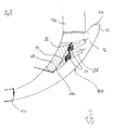
- the standard side mirror shown roughly schematically in FIG. 1 2 can via a housing bracket 16, which on Mirror base is arranged to be attached to a car.
- the interior of the housing for receiving the (not shown) Mirror glass, an adjustment mechanism or electronics etc. is on the side facing the driver from the Limited mirror glass.
- On the in the direction of travel facing side arches a housing 30 in the form of a closed half-shell made of plastic the interior around, along with one at the opposite web 40 adjoining the direction of travel delimited a recess 10.
- the surface of the Housing shell 30 is approximated to a streamlined body, i.e. as approximately semi-elliptical or parabolic Freeform surface held without edges.
- the side mirror 2 receives a slippery shape bulbous design, so that one inside for installation an additional indicator light insert is sufficient Space is available.
- the of the housing shell 30 and the web 40th included recess 10 was from the housing shell 30 milled out and corresponds to the contour of the in Fig. 2nd Bink lamp insert 1 shown in a highly schematic manner.
- the turn signal insert 1 the shape predetermined by the housing shell 30 such that the piece milled out at the recess 10 the housing shell 30 through the turn signal insert 1 is replaced, the outer surface of the mirror housing before milling and the outer surface after Installation of the turn signal lamp insert 1 essentially are congruent.
- the recess 10 is on all sides from the housing shell 30 and the web 40, the part of Housing shell 30 is enclosed, the one used Direction indicator insert 1 after installing the side mirror 2 the housing shell 30 completed in volume Recess 10 and closes to the outside.
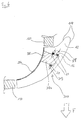
- the turn signal insert 1 has a thickness of Housing shell 30 outgoing thickness, which differs from that End facing the vehicle from flowing to one Increase 12 widened towards the rear of the vehicle pointing end reaches its greatest width. Within the Indicator insert 1 is therefore space for Light source (s) and electrical system available. At the same time with the side surface of the elevation facing the rear of the vehicle 12 created a luminous surface 14 through which light in the desired angle range of 5 - 60 ° to the transverse axis of the Vehicle in the direction facing the rear of the vehicle can leak.
- the Fixing the turn signal lamp insert 1 by gluing but also other cohesive or form-fitting ones Processes such as snap, clip or Remote nose closures, springs to be hung, etc., could be used for this.
- the turn signal lamp insert is embodied on all sides enclosed by the housing 130.
- Rear side (against the Direction of travel F) the turn signal insert 100; 200 thus from behind the turn signal insert 100; 200 bordered wall section of the mirror housing 130, which as an additional light shield for the Vehicle driver acts, which therefore also by stray light is not distracted from the traffic.
- the blinker insert 100 equipped with two light emitting diodes 20, each in a bore 118 sit, which from the inside of the Bet 100, i.e. the in the installed state for Side facing the inside of the housing, from diagonally to the rear run and the light emitted by the LEDs lead to the rear light surface 14 or 114.
- the luminous area 14 is one Embodiment of the invention located in which the Illuminated surface 14 is approximately at 90 ° to the direction of travel running, flat surface. But is preferred a nose 13 on the rear of the turn signal lamp insert 100 provided, the one drawn with a solid line Surface 114 forms the luminous surface 114.
- two LEDs are used, depending on the power of the LEDs but also the use of only one or more LEDs conceivable.
- blinking signal-colored LEDs come on used, but it would also be possible to use a different color to use luminous LEDs and the light emission by correspondingly arranged color filters in turn signal orange to color.
- the LEDs 20 are on the inside of the insert 100 inserted into the holes 118 and there in a Plastic compound 128 poured in and thus stable in position attached. Via a conductor strip 24 which is connected to the LEDs 20 is connected, the power supply takes place.
- the Conductor strip 24 does not have suitable ones on the vehicle side shown connections with which it is possible when installing the Filament insert 100 with the vehicle electrical system too connect is.
- the conductor strip 24 through the Mirror housing foot and the vehicle door with the To connect the blinker.
- the conductor strip 24 it is sufficient to have the conductor strip 24 with it to provide a suitable connector and up to Connection point.
- the conductor strip is preferred glued to the inside of the mirror housing, all the more so To ensure position stability. If you already have one electrical wiring is present, for example one electric motor in the housing for mirror adjustment, could also replace the existing wiring with A conductor strip 24 may be provided, which in addition to the wires Turn signal control cores and connections for controlling the Has mirror adjustment or heating mechanisms.
- the inside is of the turn signal insert 100 further with a reflective coating layer 126 coated, whereby a Reliable light emission in the direction of the driver's cabin is prevented and all light to the outside is reflected.
- a light emission thus takes place in Direction of travel F as well as sideways outwards and at an angle to the rear (against the direction of travel F).
- the structure of the Direction indicator 100 which is an inexpensive and in Mass production feasible manufacture of the turn signal insert 100 allowed: After a first step of Pouring, injection molding or otherwise molding the Body of the turn signal insert from a suitable, possibly translucent plastic, for example Polycarbonate or plexiglass (PMMA), in a second Step diode receiving holes 118 are drilled in, the diode mounting holes 118 are equipped with LEDs and wired to a conductor tape 24. In one subsequent step are the diodes with their electrical connections then watertight and stable cast their positions in the insert or through Application of a sealing layer 128 sealed. Finally, the reflection layer 126 is applied to the Sealing layer 128 sprayed, evaporated or otherwise applied.
- a suitable, possibly translucent plastic for example Polycarbonate or plexiglass (PMMA)
- the diode mounting holes 118 are equipped with LEDs and wired to a conductor tape 24.
- the diodes with their electrical connections then watertight and stable cast their positions in the insert or through Application of a sealing layer 128
- the installation of the turn signal lamp insert 100 is therefore possible also easy because the insert is in one piece is built up and thus only a part in the The recess provided in the mirror housing is inserted and provided on the turn signal insert 100 Anchoring elements is attached to the mirror housing 130.
- the wiring (conductor strip 24) is up to the appropriate Connection point to the vehicle electrical system.
- the wiring (strip 24), but also the shape and the fastening elements intended for use 100 are each in the series of the vehicle, or the Adjusted side mirror.
- Suitable as anchoring elements especially resilient lugs, clips, clips or Tension springs.
- the turn signal insert 200 shown in FIG. 5 according to a further embodiment of the invention for the most part the same design as the one in the Figures 3 and 4 shown, two LEDs 24 in provided receptacles 218 are arranged, which in Direction obliquely from the inside of the insert run towards the rear of the vehicle. On that one Luminous surface 114, which surrounds a nose 13, can do this radiated light in the desired angular range be broadcast. Deviating from the embodiment of the Figures 3 and 4 is on the inside behind the Light-emitting diodes 24, however, are designed as individual parts Reflector 22, in the same time holders for the LEDs 24 are provided.
- the reflector 22 is located in a further recess 218a, which in turn with Sealant 228 is poured out, making the reflector and so that the LEDs are firmly anchored in position. Also at In this embodiment of the invention, the LEDs 24 are included their electrical connections in the turn signal insert 200 thus hermetically against external interference such as Splashed water or stone chips.
- the Reflector becomes the main part of the light emitted in those lying laterally against the direction of travel F. Angular range directed behind the luminous surface F. A part the scattered light is also in the direction of travel broadcast so that the blinking signal also from oncoming road users are perceived can.
- the turn signal insert 200 shown in FIG. 5 leaves thus essentially the same Manufacturing process like that in Figures 3 and 4 Manufacture blinker insert 100 shown. Instead of that Insert the individual LEDs in the designated ones
- the embodiment of the invention shown in FIG. 6 there is an additional LED radiating in the direction of travel 21 in a corresponding additional mounting hole 319, so that it also faces in the direction of travel F. Light emission takes place.
- the receiving bore 319 is in the wall of the receptacle facing the direction of travel F. 318a drilled while in the rear wall of the Recording 318a two with opposite to the direction of travel emitting LEDs 20 equipped mounting holes 318 are drilled in.
- a Signal radiation in the direction of travel even when as Pouring compound 328 an opaque or strong reflective material is used that the Light emission from the two light emitting diodes 20 in the opposite direction area in the direction of travel.
- FIG. 7 At 30 is a standard side mirror housing of the vehicle side mirror referred to that via a housing bracket 16, or a suspension 16 is attached to the vehicle and surrounds a mirror glass 50.
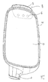
- a luminous element insert 400 On the of the housing bracket 16 opposite side of the mirror housing 30 (outside) a luminous element insert 400 can be seen, which with a luminous area 414 over the outer contour of the Mirror housing 400 protrudes and the top down curved course of the outer contour of the mirror housing 400 follows.
- the position of the Filament insert 400 on the back of the Side mirror indicated.
- the housing of the standard side mirror is as a continuous half-shell designed.
- the filament insert 400 is closer shown.
- the filament insert 400 is in the essentially bowl-shaped.
- On the mirror glass 50 At the end facing the rear of the vehicle is an adhesive flange 425 in front and at its end facing the vehicle front a projection or nose 419.
- Projection 419 can be the lamp insert 400 with the Inner contour of the mirror housing 30 are glued.
- a circuit board 435 is inserted.
- the circuit board is supported on a shoulder Opening 418 off.
- the LEDs 420 would be glued or the circuit board 435 in the opening 418 possible.
- the opening 418 with a sealing material 437, for example synthetic resin, waterproof sealed or been poured out.
- a connecting line 424 for the LEDs 420 is from the Body 419 led out and on the inner contour of the Housing 30 relocated, preferably glued. Also a rear connector, as designated in Fig. 10 with 439, would be conceivable.
- the wiring 424 can be on the vehicle side have suitable connections, not shown, with which it when installing the filament insert 400 with the Vehicle electrics can be connected. Depending on the type of vehicle can be provided, for example, the conductor strip 424 through the mirror housing base and the vehicle door to connect the flasher or one previously dead Use the connection in the mirror housing for this.
- the light conduction from the LEDs 420 to the luminous area 414 takes over a light-guiding body 429 of the Luminous element insert 400, which if possible from a transparent plastic, for example polycarbonate or Plexiglass (PMMA) is poured.
- a transparent plastic for example polycarbonate or Plexiglass (PMMA) is poured.
- PMMA Plexiglass
- the inside of the light guiding body 429 becomes thereby over its entire length by a reflector part 431 shielded against the interior of the housing.
- the reflector part 431 can, for example, consist of a black plastic, which on the to chrome-plated light-guiding body 429, is preferably steamed.
- the reflector part 431 and the light-guiding bodies 429 are only in the area of the flange 425 and the projection 419.
- the light guiding body 429 with the drilled Opening 418, the LED circuit board unit 420, 435 and that Reflector part 431 are prefabricated and then assembled into a one-piece unit and waterproof or glued.
- a luminous element insert 400 is thus created, which is robust against stone chips and splash water and one good light emission in the desired angular range (a against the vehicle's longitudinal axis against the direction of travel 30 - 85 ° outward inclined angular range) guaranteed.
- Such an effect can also be increased Refractive index or reflectance on the outer surface in the front area of the outer contour of the insert 400 be achieved.
- FIG. 5 shows a luminous element insert 500, which completes the housing shell 30 by volume and at an elevation 517 on its in the direction of travel F projecting end protrudes inwards. At the increase 517 connects a nose 519, in which the light-emitting diode 520 is recorded and sealed. Despite the lack of one end elevation, or a counter to the direction of travel Pointing luminous area, the light can be in the desired Angular range can be emitted. Inside is the Luminous body insert 500 with a reflective layer 528 steamed.
- the Inner surface of the turn signal insert is opaque, to be coated or reflective.
- Embodiments could be achieved through an additional, at least partially applied mirroring of the images 218a; 318a, for example in the form of a lacquer layer, a additional focusing of the light radiation in the desired direction.
- FIGS. 7 to 10 Design the attachment of the turn signal insert 400 in the mirror housing 30 by gluing.
- other cohesive or but positive procedures are used, such as for example with snap, clip or spring nose closures, springs to be hung etc.
Abstract
Description
Die Erfindung betrifft einen Leuchtkörper-Einsatz zum nachträglichen Einbau in Standard-Fahrzeugseitenspiegel und einen Bausatz dafür.The invention relates to a filament insert for retrofitting in standard vehicle side mirrors and a kit for it.
Schon seit langem ist es prinzipiell bekannt, Kfz mit in den Seitenspiegeln integrierten Blinkleuchten auszurüsten, um die Erkennbarkeit von Abbiege- bzw. Spurwechsel- oder Warnsignalen zu verbessern. Beispielhaft sei dazu die englische Schrift GB 2 266 870 A genannt.In principle, it has long been known to use motor vehicles Indicator lights integrated in the side mirrors equip in order to make the turn or Improve lane change or warning signals. exemplary may be mentioned in English GB 2 266 870 A.
Im Zuge der Entwicklung wurde dabei deutlich, dass das Blinkersignal insbesondere für nachfolgende Verkehrsteilnehmer wichtig ist. Der Gesetzgeber hat daher Richtlinien erlassen, nach denen in den Seitenspiegeln von Kraftfahrzeugen befindliche Blinkleuchten in einem gegen die Fahrzeuglängsachse entgegen der Fahrtrichtung um 30-85° nach außen geneigten Winkelbereich Licht abstrahlen müssen. Auch bezüglich der Lichtstärke im genannten Winkelbereich bestehen gesetzliche Regelungen. Daneben sollen derartige Blinker auch nach vorne Licht abstrahlen, wobei dafür keine Mindestlichtmenge festgelegt ist.In the course of the development, it became clear that the Turn signal especially for subsequent road users important is. The legislature therefore has Issue guidelines according to which in the side mirrors of Indicator lights located in motor vehicles in a counter the vehicle's longitudinal axis against the direction of travel by 30-85 ° Radiate outward inclined angular range of light have to. Also with regard to the light intensity in the above There are legal regulations. Besides such indicators should also emit light towards the front, whereby no minimum amount of light is specified.
Mehr und mehr gehen namhafte Autobauer dazu über, ihre Autos mit derartigen in den Seitenspiegel integrierten Blinkern auszurüsten.Well-known car manufacturers are increasingly turning to theirs Cars with such integrated in the side mirror Equip turn signals.
So weist beispielsweise die in der Gebrauchsmusterschrift DE 297 02 746 U1 vorgeschlagen Seitenspiegel-Blinker-Einheit am fahrzeugzugewandten Ende der Einheit eine Lichtquelle auf, deren Licht mittels eines Lichtleiters zum fahrzeugabgewandten Ende der Einheit gesendet wird, um so den erforderlichen Winkelbereich auszuleuchten, während gleichzeitig der am fahrzeugzugewandten Ende der Seitenspiegel-Blinker-Einheit verhältnismäßig reichlich vorhandene Raum zum Unterbringen der Lichtquelle genutzt wird.For example, that in the utility model DE 297 02 746 U1 proposed side mirror turn signal unit at the end of the unit facing the vehicle a light source, the light of which by means of a Optical fiber to the end of the unit facing away from the vehicle is sent, so the required angular range illuminate while at the same time facing the vehicle End of the side mirror turn signal unit relatively abundant space to accommodate the light source is used.
Eine weitere Seitenspiegel-Blinker-Einheit, mit der die gesetzlich vorgeschriebene Abstrahlungscharakteristik erzielt wird, wird in der deutschen Patentanmeldung DE 198 28 253 A1 beschrieben. Im Gehäuse des dortigen Kfz-Seitenspiegels ist eine Lichtquelle vorgesehen, die Licht in den entgegen der Fahrtrichtung liegenden Bereich abstrahlt. Als zusätzliche Lichtquelle ist auf der entgegenkommenden Fahrzeugen zugewandten Seite der Seitenspiegel-Blinker-Einheit eine Leuchtfolie aufgebracht, so dass die seitlich nach hinten abstrahlende Lcihtquelle klein dimensioniert werden kann, beispielsweise in Form einer LED.Another side mirror turn signal unit with which the radiation characteristics required by law is achieved is in the German patent application DE 198 28 253 A1. In the housing of the side mirror there a light source is provided, the light in the area opposite to the direction of travel radiates. As an additional light source is on the oncoming side of the vehicle Side mirror indicator unit applied a luminescent film, so that the light source radiating laterally to the rear can be dimensioned small, for example in the form an LED.
Des Weiteren zeigt die europäische Offenlegungsschrift EP 997 346 A1 eine Seitenspiegel-Blinker-Einheit, bei der im Gehäuse der Einheit auf der fahrzeugabgewandten Seite getrennte Lichtquellen einerseits in den vor dem Fahrzeug liegenden Bereich ausstrahlen und andererseits in den entgegen der Fahrtrichtung um bis zu 60° nach außen geneigten Winkelbereich. Das Licht der entgegen der Fahrtrichtung strahlenden Blinkleuchte wird dabei mittels eines elipsoidischen Reflektors in den gewünschten Winkelbereich gelenkt.Furthermore, the European published specification shows EP 997 346 A1 a side mirror turn signal unit in which in the housing of the unit on the side facing away from the vehicle separate light sources on the one hand in front of the vehicle radiate area and on the other hand in the against the direction of travel by up to 60 ° to the outside inclined angular range. The light of the opposite The direction indicator, which shines in the direction of travel, is an ellipsoidal reflector in the desired Angular range steered.
Auch die weitere Schrift US 2001/0026455 A1 zeigt einen Blinker-Einsatz, der in ein speziell angepasstes Seitenspiegelgehäuse einbaubar ist. Dabei kann in eine Aufnahme mit entsprechenden Halterungen eines modifizierten Seitenspiegelgehäuses wahlweise eine bloße Abdeckung oder eine fest verbundene Einheit aus einem Dekorativschalenelement und dem Blinkereinsatz eingesetzt werden. The other document US 2001/0026455 A1 also shows one Turn signal insert, which in a specially adapted Side mirror housing can be installed. It can be done in a Recording with appropriate brackets of a modified Side mirror housing either a bare cover or a firmly connected unit from a decorative shell element and the turn signal insert.
Die in den genannten Schriften gezeigten Seitenspiegel sind für die Erstausrüstung von PKWs gedacht. die Seitenspiegel weisen daher jeweils speziell gestaltete Seitenspiegelgehäuse auf, in welche mehr oder minder komplizierte, aus mehreren Einzelteilen bestehende Blinksignalgeberanordnungen eingebaut sind. Anders ausgedrückt, die dort gezeigten Blinker-Baugruppen erfordern jeweils ein speziell angepasstes Spiegelgehäuse.The side mirrors shown in the cited documents are intended for the original equipment of cars. the Side mirrors therefore each have specially designed Side mirror housing in which more or less complicated, consisting of several individual parts Blinker signal arrangements are installed. Different expressed, the turn signal assemblies shown there each require a specially adapted mirror housing.
Es besteht nun auch bei Besitzern älterer oder preisgünstigerer Autos das Bedürfnis, ihren Wagen mit in die Seitenspiegel integrierten Blinkern aufzuwerten. Diese bis heute überwältigende Mehrheit an Fahrzeugen haben serienmäßige Standard-Fahrzeugseitenspiegel, die nicht zum nachträglichen Einbau eines Blinkers vorgerüstet sind. Das Spiegel-Gehäuse besteht dabei in gängiger Weise im wesentlichen aus einer Schale, die das Spiegelglas und die dahinterliegende Mechanik/Elektrik einfasst. Es versteht sich dabei von selbst, dass sich die nachgerüsteten Seitenspiegel designmäßig ins Bild des Fahrzeugs einfügen müssen.It now exists among owners of older or cheaper cars the need to bring their car in to upgrade the side mirrors integrated turn signals. This have an overwhelming majority of vehicles to date Standard vehicle side mirrors that are not standard retrofitting a turn signal. The Mirror housing consists in the usual way in essentially from a bowl that the mirror glass and the mechanics / electrics behind it. It understands it goes without saying that the retrofitted Insert the side mirror into the image of the vehicle by design have to.
Hiervon ausgehend ist es Aufgabe der Erfindung, ein Verfahren zu schaffen, mit dem das Nachrüsten bestehender, serienmäßiger Seitenspiegel gängiger Kfz-Typen, deren Gehäuse nicht von vorne herein zur Aufnahme eines Blinklichts vorgesehen ist, zu Seitenspiegel-Blinker-Einheiten auf einfache Weise und kostengünstig zu ermöglichen, sowie jeweils einen dafür geeigneten Leuchtkörpereinsatz und Bausatz zu schaffen.Proceeding from this, it is an object of the invention to: To create processes with which the retrofitting of existing standard side mirrors of common vehicle types, their Housing not from the beginning to accommodate one Blinking lights are provided for side mirror turn signal units in a simple and inexpensive way enable, as well as a suitable one To create a lamp insert and kit.
Diese Aufgabe wird hinsichtlich des Leuchtkörpereinsatzes durch die Merkmale des Anspruchs 1 gelöst, hinsichtlich des Verfahrens durch die Merkmale des Anspruchs 29 und hinsichtlich des Bausatzes durch die Merkmale des Anspruchs 25. This task is carried out with regard to the use of luminous elements solved by the features of claim 1, regarding the procedure by the characteristics of the Claim 29 and in terms of the kit by the Features of claim 25.
In ihrer Form vorgegebene, serienmäßig bei gängigen Kfz-Typen eingesetzte Standard-Seitenspiegel weisen typischerweise ein Spiegelgehäuse auf, das nicht von vorne herein zur Aufnahme eines Blinklichts vorgesehen ist, und als durchgängige Schale ausgeförmt ist, welche einen Spielgelinnenraum mehrseitig umschließt, in dem das Spiegelglas und eine eventuell vorgesehene Elektrik und/oder Mechanik zur Verstellung und/oder Heizung des Spiegelglases untergebracht ist.Specified in their form, standard in common Standard side mirrors used in vehicle types typically a mirror housing that is not from the front is provided for receiving a flashing light, and is shaped as a continuous shell, which one Surrounds play area on several sides, in which the Mirror glass and any electrical system provided and / or mechanics for adjusting and / or heating the Mirror glass is housed.
Mit dem erfindungsgemäßen Verfahren können derartige Standard-Seitenspiegel bestehender Alt-PKWs auf einfache und kostengünstige Weise und unter geringem Zeitaufwand zu Seitenspiegel-Blinker-Einheiten nachgerüstet werden.With the method according to the invention, such Standard side mirror of existing old cars on simple and inexpensive way and in a short amount of time Side mirror turn signal units can be retrofitted.
Erfindungsgemäß ist ferner ein als separate Einheit ausgeführter Leuchtkörper-Einsatz vorgesehen, der in bestehende Fahrzeug-Seitenspiegel eingebaut werden kann. Der Einsatz schließt die Gehäuseaussparung dabei nach außen hin ab. Wenngleich auch ein Spalt zwischen Einsatz und Gehäuse toleriert werden kann, da auch bestehende Spiegel nicht vollständig wasserdicht abgedichtet sind, ist die Aussparung doch vorzugsweise vollständig abgedichtet.According to the invention is also a separate unit executed lamp insert provided in existing vehicle side mirrors can be installed. The insert closes the housing recess to the outside down. Even if there is a gap between use and Housing can be tolerated because existing mirrors are not completely watertight sealed Cutout preferably completely sealed.
Es gelingt damit, einen robust aufgebauten Einsatz zu schaffen, mit dem die Blinkerfunktion bei einem Kfz mit bestehenden Standard-Seitenspiegeln mit möglichst geringem Umbauaufwand nachgerüstet werden kann, ohne das Design zu beeinträchtigen.It succeeds in a robustly constructed application create with which the turn signal function in a motor vehicle existing standard side mirrors with as little as possible Conversion effort can be retrofitted without the design too affect.
Es gelingt ferner, die gesetzlich vorgegebene Abstrahl-Winkelbereich einzuhalten.It also succeeds in the legally prescribed radiation angle range observed.
Der Leuchtkörper-Einsatz ist dabei einstückig und als Vollkörper ausgeführt und ist dadurch robust und leicht handhabbar im Aufbau und beim Einbau. Der Leuchtköper-Einsatz kann dabei nahezu vollständig , d.h. bis auf Leuchtmittel und Lichtabdichtung zum Innenraum hin, aus transparentem Kunststoff bestehen.The lamp insert is in one piece and as Full body design and is therefore robust and light manageable in construction and installation. The luminous insert can be almost complete, i.e. until Illuminant and light seal towards the interior, off transparent plastic.
Vorteilhaft weist der erfindungsgemäße Einsatz dabei am Frontende eine in Fahrtrichtung weisende Erhöhung auf, mit der er ins Spiegelgehäuseinnere vorsteht. Dort steht somit Bauraum im Einsatz zur Verfügung, um ein Leuchtmittel aufzunehmen. Das Leuchtmittel strahlt dabei durch den Körper des Einsatzes hindurch in den gewünschten Abstrahlbereich, der seitlich nach hinten gerichtetet ist. Daneben ist das Blinkersignal aber auch von entgegenkommenden Verkehrsteilnehmern wahrnehmbar.The use according to the invention advantageously has Front end with an increase pointing in the direction of travel which he projects into the interior of the mirror housing. So it says there Installation space available to use an illuminant take. The illuminant shines through the Body of the insert into the desired one Beam area that is directed sideways to the rear. In addition, the turn signal is also off oncoming road users perceptible.
Vorteilhaft hat der Leuchtkörper-Einsatz im eingebauten Zustand zudem an seiner dem Fahrzeugheck zugewandten Seite eine Erhöhung, an der der Leuchtkörper-Einsatz aus dem Seitenspiegelgehäuse hervortritt, um eine zum Fahrzeugheck weisende Leuchtfläche freizulegen. Lediglich an der Erhöhung, weicht die Form des Spiegelgehäuses bei eingesetztem Leuchtkörper-Einsatz von der Standard-Außenkontur ab. Ansonsten fügt sich der Leuchtkörper-Einsatz nahtlos in das Standard Blinkergehäuse ein bzw. vervollständigt dieses volumenmäßig nach außen hin und schließt es zur Außenseite hin ab. Somit bleiben die aerodynamischen Eigenschaften eines in Serie gefertigten Standardspiegelgehäuses weitgehend erhalten. Auch die Stabilität des Spiegelgehäuses wird nicht beeinträchtigt.The built-in lamp insert has an advantage Condition also on its side facing the rear of the vehicle an increase at which the filament insert from the Side mirror housing emerges from one to the rear of the vehicle exposing pointing light surface. Only on the Raises, softens the shape of the mirror housing insert used from the standard outer contour from. Otherwise the filament insert fits seamlessly into the standard turn signal housing or completes this volume outwards and closes it to the outside. So they stay aerodynamic properties of a mass-produced Standard mirror housing largely preserved. Also the The stability of the mirror housing is not affected.
Grundsätzlich ist die Form, die Geometrie und die Einbaulage des Leuchtkörper-Einsatzes nicht konkret beschränkt. Sie wird in Abhängigkeit von der Form des Spiegels, seiner Ausrichtung zum Fahrzeug und dem gewünschten, zu erzielenden Sicherheitseffekt gewählt. Wenn die Außenkontur des Spiegelgehäuses quer zur Fahrzeuglängsache konvex ausgewölbt ist, kann der Leuchtkörper-Einsatz sogar eine mit der Außenkontur des Standard-Fahrzeugseitenspiegels ündige Außenoberfläche haben und trotzdem eine entgegen der Fahrzeuglängsachse weisende Leuchtfläche ausbildent und in das Spiegelgehäuse an einer Stelle eingesetzt ist, an Der Leuchtkörper-Einsatz kannBasically the shape, the geometry and the Installation position of the filament insert not specific limited. It will depend on the shape of the Mirror, its orientation to the vehicle and the desired security effect to be achieved. If the outer contour of the mirror housing transverse to Longitudinal vehicle is convex, can Luminaire insert even one with the outer contour of the Standard vehicle side mirror flush outer surface and still have one against the vehicle's longitudinal axis trained pointing surface and into the mirror housing is inserted in one place, on the filament insert can
In der vorteilhaften Ausführungsform nach Anspruch 15 vervollständigt der Leuchtkörper-Einsatz das Spiegelgehäuse volumenmäßig. Im Bereich der Erhöhung, an der der Leuchtkörper-Einsatz aus dem Seitenspiegelgehäuse hervortritt, steht somit Bauraum zur Verfügung, um ein Leuchtmittel aufzunehmen.In the advantageous embodiment according to claim 15 the lamp insert completes the mirror housing in terms of volume. In the area of the increase at which the Luminaire insert from the side mirror housing emerges, there is thus space available for a Record bulbs.
In der vorteilhaften Weiterbildung nach Anspruch 5 schließt an die heckseitige Erhöhung bzw. die Leuchtfläche des Blinkleuchten-Einsatzes eine Nase an, die im eingebauten Zustand am heckseitigen Rand der Aussparung des Spiegelgehäuses entgegen der Fahrtrichtung übersteht. Es hat sich gezeigt, dass auf diese Weise der Anteil des von der Lichtquelle des Blinkleuchten-Eindsatzes ausgesandten Lichts, das in den gewünschten Winkelbereich gelenkt wird, erhöht werden kann. Je nach den Brechungs-, Streuungs- und Reflexionseigenschaften u.ä. des Trägermaterials des Blinkleuchten-Einsatzes kann dabei die Formgebung der Nase variiert werden.In the advantageous further development according to claim 5 connects to the rear elevation or the illuminated area of the turn signal lamp insert a nose that in installed condition at the rear edge of the recess of the Mirror housing protrudes against the direction of travel. It has shown that in this way the proportion of the the light source of the turn signal insert Light that is directed into the desired angular range can be increased. Depending on the refraction, scattering and Reflection properties and the like of the carrier material of the Turn signal lights can use the shape of the nose can be varied.
Vorteilhaft ist es gemäß Anspruch 6, den Leuchtkörper-Einsatz mit zumindest einer Leuchtdiode (LED) als Leuchtmittel und einem Träger mit einer lichtführenden Schicht aus lichtleitendem Material, vorzugsweise transparentem Kunststoff, auszustatten.It is advantageous according to claim 6, the filament insert with at least one light emitting diode (LED) as Illuminant and a support with a light-guiding Layer of light-conducting material, preferably transparent plastic to equip.
Dabei ist die Leuchtdiode bevorzugt hinter der Leuchtfläche in einer Ausnehmung im Träger angeordnet.The LED is preferably behind the Luminous surface arranged in a recess in the carrier.
Durch die kleine Baugröße von Leuchtdioden gelingt es auf vorteilhafte Weise, dem Leuchtkörper-Einsatz eine schlanke Form zu geben, so dass er sich ideal in das Spiegelgehäuse einfügt, ohne zuviel Bauraum im Gehäuseinneren zu beanspruchen. LEDs erzeugen darüber hinaus nur geringe Verlustwärme und haben dadurch eine lange Lebensdauer, so dass die Diode wartungsfrei fest eingebaut werden kann, ohne dass ein nachträgliches Austauschen der Diode möglich sein muss.The small size of light emitting diodes makes it possible in an advantageous manner, the filament insert a to give slim shape so that it fits ideally into that Inserts mirror housing without too much space in the To stress the interior of the housing. LEDs generate over it only low heat loss and therefore have a long life, making the diode maintenance-free fixed can be installed without a subsequent It must be possible to replace the diode.
Um eine Beeinträchtigung des Fahrers auszuschließen, ist in der vorteilhaften Weiterbildung gemäß Anspruch 8 darüber hinaus eine Abdichtung vorgesehen, welche die Ausnehmung, in der die Leuchtdiode sitzt gegen die zum Spiegelgehäuseinneren, also zum Fahrer hin weisende Seite, abdichtet. Vorteilhaft ist die Abdichtung reflektierend, so dass die gesamte Abstrahlung in die gewünschte Richtung geleitet wird.To rule out any impairment to the driver, is in the advantageous development according to claim 8 in addition, a seal is provided which the Recess in which the LED sits against the Inside the mirror housing, i.e. the side facing the driver, seals. The seal is advantageously reflective, so that the entire radiation is in the desired direction is directed.
Die reflektierende Abdichtung kann dabei als einzelnes Reflektor-Bauteil vorgesehen sein. Im Falle mehrerer Leuchtdioden können auch mehrere Reflektoren vorgesehen sein. Alternativ oder zusätzlich dazu kann eine reflektierende Schicht auf die zur Innenseite des Spiegelgehäuses weisende Oberfläche aufgebracht werden. Geeignet dafür sind etwa Lacke, aufgedampfte oder aufgespritzte Schichten.The reflective seal can be done as a single Reflector component can be provided. In the case of several Light-emitting diodes can also be provided with several reflectors his. Alternatively or in addition, a reflective layer on the inside of the Mirror housing facing surface are applied. Lacquers, vapor-deposited or are suitable for this sprayed layers.
Vorteilhaft ist die Leuchtdiode mitsamt ihres elekrischen Anschlusses in die Ausnehmung eingesiegelt. Die Versiegelung kann dabei durch ein Vergießen mit Kunststoff, beispielsweise Kunstharz erfolgen. Auf diese Weise ist gewährleistet, dass, selbst wenn Leuchtkörpereinheit und Spiegelgehäuse nicht wasserdicht aneinander anliegen, die gesamte Elektrik des Leuchtkörpereinsatzes hermetisch von sämtlichen Außeneinflüssen abgeschottet ist. Auch ein gewisser Schutz gegen mechanische Fremdeinwirkungen (z.B. Stöße) ist somit gegeben, so dass sich der Leuchtkörpereinsatz sowohl in der Lagerung und beim Transport als auch im eingebauten Zustand als robust gegen Beschädigungen erweist.The LED together with yours is advantageous electrical connection sealed into the recess. The Sealing can be done by potting with plastic, for example, synthetic resin. That way ensures that even if filament unit and The mirror housing should not lie against each other in a watertight manner entire electrics of the filament insert hermetically sealed is isolated from all external influences. Also a certain protection against external mechanical influences (e.g. Shocks) is given, so that the Luminaire insert both in storage and when Transport as well as when installed as robust against Shows damage.
Zur Befestigung des Leuchtkörper-Einsatzes im Spiegelgehäuse sind vorteilhaft federnde Nasen an der Außenkontur des Leuchtkörper-Einsatzes vorgesehen, mit denen eine formschlüssige Verbindung hergestellt werden kann. Aber auch ein Einspannen mittels Federelementen oder ein Verschrauben mit dem Spiegelgehäuse wäre denkbar, je nach Form und Material des Spiegelgehäuses, für das der jeweilige Leuchtkörper-Einsatz hergestellt wird.To attach the filament insert in the Mirror housings are advantageous resilient lugs on the Provided outer contour of the filament insert, with which a positive connection are made can. But also clamping using spring elements or screwing to the mirror housing would be conceivable, depending according to the shape and material of the mirror housing for which the respective filament insert is manufactured.
Zudem wäre ein Einkleben des Leuchtkörpereinsatzes im Stumpfstoß denkbar. Vorteilhaft sind jedoch am Leuchtkörper-Einsatz parallel zur Innenkontur des Spiegelgehäuses Flansche vorgesehen, an denen der Leuchtkörper-Einsatz in das Gehäuse einklebbar ist. Es kann auch ein umlaufender Flansch vorgesehen sein.In addition, gluing the lamp insert in the Butt joint conceivable. However, are advantageous on Luminaire insert parallel to the inner contour of the Mirror housing flanges provided on the Luminous element insert can be glued into the housing. It can a circumferential flange can also be provided.
Vorteilhafte Weiterbildungen sind Gegenstand der weiteren Unteransprüche. Dabei versteht es sich von selbst, dass die vorstehend genannten und die nachstehend noch zu erläuternden Merkmale nicht nur in der angegebenen Kombination, sondern auch in anderen Kombinationen oder in Alleinstellung sowie in Kombination mit den im Hauptpatent DE 102 382 64 beschriebenen Merkmalen verwendbar sind, ohne den Rahmen der Erfindung zu verlassen.Advantageous further developments are the subject of further subclaims. It goes without saying that the above and those below too explanatory features not only in the specified Combination, but also in other combinations or in Unique and in combination with those in the main patent Features described in DE 102 382 64 can be used without to leave the scope of the invention.
In den folgenden Figuren werden vorteilhafte Ausführungsformen der Erfindung gezeigt. Es zeigen:The following figures are advantageous Embodiments of the invention shown. Show it:
Nachfolgend werden anhand schematischer Zeichnungen
bevorzugte Ausführungsformen der Erfindung näher erläutert.
Es zeigen:
Der in der Fig. 1 grob schematisiert gezeigte Standard-Seitenspiegel
2 kann über eine Gehäusehalterung 16, die am
Spiegelfuß angeordnet ist, an einem Pkw befestigt werden.
Der Gehäuseinnenraum zur Aufnahme der (nicht gezeigten)
Spiegelglasscheibe, einer Verstellmechanik oder -elektrik
etc. wird auf der dem Fahrer zugewandten Seite von der
Spiegelglasscheibe begrenzt. Auf der in Fahrtrichtung
weisenden Seite wölbt sich ein Gehäuse 30 in Form einer
geschlossenen Halbschale aus Plastik- bzw. Kunststoff um
den Innenraum herum, die zusammen mit einem an der entgegen
der Fahrtrichtung gelegenen Seite anschließenden Steg 40
eine Aussparung 10 eingrenzt. Die Oberfläche der
Gehäuseschale 30 ist einem Stromlinienkörper angenähert,
d.h. als annähernd teil-eliptische oder parabolische
Freiformfläche ohne Kanten gehalten. Durch die
windschlüpfrige Formgebung erhält der Seitenspiegel 2 eine
bauchige Bauform, so dass im Gehäuseinneren ein zum Einbau
eines zusätzlichen Blinkleuchten-Einsatzes ausreichendes
Platzangebot vorhanden ist.The standard side mirror shown roughly schematically in FIG. 1
2 can via a
Die von der Gehäuseschale 30 und dem Steg 40
eingeschlossene Aussparung 10 wurde aus der Gehäuseschale
30 herausgefräst und entspricht der Kontur des in Fig. 2
stark schematisiert gezeigten Binkleuchten-Einsatzes 1.
Nach Einbau des Binkleuchten-Einsatzes 1 in die
Gehäuseschale 30 vervollständigt der Blinkleuchten-Einsatz
1 dabei die durch die Gehäuseschale 30 vorgegebene Form
derart, dass das an der Aussparung 10 herausgefräste Stück
der Gehäuseschale 30 durch den Blinkleuchten-Einsatz 1
ersetzt wird, wobei die Außenoberfläche des Spiegelgehäuses
vor dem Herausfräsen und die Außenoberfläche nach dem
Einbau des Blinkleuchten-Einsatzes 1 im wesentlichen
deckungsgleich sind. Die Aussparung 10 ist auf allen Seiten
von der Gehäuseschale 30 und dem Steg 40, der Teil der
Gehäuseschale 30 ist, umschlossen, wobei der eingesetzte
Blinkleuchten-Einsatz 1 nach dem Einbau den Seitenspiegel 2
die Gehäuseschale 30 volumenmäßig vervollständigt an der
Aussparung 10 und nach außen hin abschließt.The of the
Der Blinkleuchten-Einsatz 1 hat eine von der Dicke der
Gehäuseschale 30 ausgehende Dicke, die sich vom der
Fahrzeugfront zugewandten Ende aus fließend zu einer
Erhöhung 12 verbreitert, die am zum Fahrzeugheck hin
weisenden Ende ihre größte Breite erreicht. Innerhalb des
Blinkleuchten-Einsatzes 1 ist somit Raum für
Lichtquelle(n)und Elektrik vorhanden. Gleichzeitig ist mit
der dem Fahrzeugheck zugewandten Seitenfläche der Erhöhung
12 eine Leuchtfläche 14 geschaffen, durch die Licht in den
gewünschten Winkelbereich von 5 - 60° zur Querachse des
Fahrzeugs in der dem Fahrzeugheck zugewandten Richtung
austreten kann.The turn signal insert 1 has a thickness of
Housing shell 30 outgoing thickness, which differs from that
End facing the vehicle from flowing to one
Bei der dargestellten Ausfünrungsform erfolgt die Befestigung des Blinkleuchten-Einsatzes 1 durch Einkleben. Aber auch andere stoffschlüssige oder aber formschlüssige Verfahren, wie beispielsweise mit Schnapp-, Clips- oder Ferdernasenverschlüsse, einzuhängende Federn u.ä., könnten hierzu eingesetzt werden.In the embodiment shown, the Fixing the turn signal lamp insert 1 by gluing. But also other cohesive or form-fitting ones Processes such as snap, clip or Remote nose closures, springs to be hung, etc., could be used for this.
Auch bei den in den weiteren Figuren dargestellten
Ausführungsformen ist der Blinkerleuchten-Einsatz allseitig
vom Gehäuse 130 umschlossen. Heckseitig (entgegen der
Fahrtrichtung F) wird der Blinkleuchten-Einsatz 100; 200
damit vom hinter dem Blinkleuchten-Einsatz 100; 200
liegenden Wandabschnitt des Spiegelgehäuses 130 eingefasst,
der als zusätzliche Lichtschutzblende für den
Fahrzeuglenker fungiert, der somit auch durch Streulicht
nicht vom Verkehrsgeschehen abgelenkt wird.Also in those shown in the other figures
The turn signal lamp insert is embodied on all sides
enclosed by the
Bei der in den Figuren 3 und 4 gezeigten
Ausführungsform der Erfindung ist der Blinkleuten-Einsatz
100 dabei mit zwei Leuchtdioden 20 bestückt, die jeweils in
einer Bohrung 118 sitzen, welche von der Innenseite des
Einsatzes 100, d.h. der im eingebauten Zustand zum
Gehäuseinneren weisenden Seite, aus schräg nach hinten
verlaufen und das von den Leuchtdioden ausgesandte Licht
zur heckseitigen Leuchtfläche 14, bzw. 114 leiten. Mit
gestrichelter Linie ist dabei die Leuchtfläche 14 einer
Ausführungsform der Erfindung eingezeichnet, bei der die
Leuchtfläche 14 eine in etwa unter 90° zur Fahrtrichtung
verlaufende, ebene Oberfläche ist. Bevorzugt ist aber
heckseitig am Blinkleuchten-Einsatz 100 eine Nase 13
vorgesehen, deren mit durchgezogener Linie eingezeichnete
Oberfläche 114 die Leuchtfläche 114 bildet. Denn unter
Ausnutzung der im Trägermaterial (Kunststoff) des Einsatzes
100 stattfindenden Lichtbrechung und -streuung gelingt es
so, eine genügende Lichtmenge in den gewünschten
Leuchtbereich auszustrahlen, der 5° - 60° gegenüber der
Fahrzeugquerachse nach hinten geneigt ist.The one shown in FIGS. 3 and 4
One embodiment of the invention is the
Bei der gezeigten Ausführungsform werden zwar zwei Leuchtdioden eingesetzt, je nach Leistung der LEDs wären aber auch der Einsatz von nur einem oder mehrere LEDs denkbar. Dabei kommen blinkersignalfarben leuchtende LEDs zum Einsatz, es wäre aber auch möglich, andersfarbig leuchtende LEDs zu verwenden und die Lichtabstrahlung durch entsprechend angeordnete Farbfilter in Blinkersignal-Orange einzufärben.In the embodiment shown, two LEDs are used, depending on the power of the LEDs but also the use of only one or more LEDs conceivable. In the process, blinking signal-colored LEDs come on used, but it would also be possible to use a different color to use luminous LEDs and the light emission by correspondingly arranged color filters in turn signal orange to color.
Die LEDs 20 sind dabei an der Innenseite des Einsatzes
100 in die Bohrungen 118 eingeschoben und dort in eine
Kunststoffmasse 128 eingegossen und somit lagestabil
befestigt. Über ein Leiterband 24, das an die LEDs 20
angeschlossen ist, erfolgt die Stromversorgung. Das
Leiterband 24 weist dabei fahrzeugseitig geeignete, nicht
gezeigte Anschlüsse auf, mit denen es beim Einbau des
Leuchtkörper-Einsatzes 100 mit der Fahrzeugelektrik zu
verbinden ist. The
Je nach Typ des Fahrzeugs kann dabei beispielsweise
vorgesehen sein, das Leiterband 24 durch den
Spiegelgehäusefuß und die Fahrzeugtüre mit dem
Blinksignalgeber zu verbinden. Bei Fahrzeugtypen, die schon
eine entsprechende Anschlussmöglichkeit im Spiegelgehäuse
aufweisen, reicht es dagegen aus, das Leiterband 24 mit
einem passenden Anschlussstecker zu versehen und bis zur
Anschlußstelle durchzuführen. Bevorzugt wird das Leiterband
dabei innenseitig mit dem Spiegelgehäuse verklebt, um so
Lagestabilität zu gewährleisten. Falls schon eine
elektrische Verkabelung vorhanden ist, beispielsweise eines
im Gehäuse sitzenden Elektromotors zum Spiegelverstellen,
könnte auch ein Ersatz der vorhandenen Verkabelung durch
ein Leiterband 24 vorgesehen sein, das neben den Adern zur
Blinkeransteuerung Adern und Anschlüsse zur Ansteuerung der
Spiegelverstell- bzw. Heizmechanismen aufweist.Depending on the type of vehicle, for example
be provided, the
Wie der Figur 4 zu entnehmen ist, ist die Innenseite
des Blinkleuchten-Einsatzes 100 des Weiteren mit einer
reflektierenden Lackschicht 126 überzogen, wodurch eine
Lichtabstrahlung in Richtung Fahrerkabine zuverlässig
verhindert wird und sämtliches Licht zur Außenseite hin
reflektiert wird. Eine Lichtabstrahlung erfolgt somit in
Fahrtrichtung F als auch seitlich nach außen und schräg
nach hinten (entgegen der Fahrtrichtung F).As can be seen in FIG. 4, the inside is
of the
Insgesamt ergibt sich somit ein Aufbau des
Blinkleuchten-Einsatzes 100, der eine kostengünstige und in
Massenproduktion durchführbare Fertigung des Blinkleuchten-Einsatzes
100 erlaubt: Nach einem ersten Schritt des
Gießens, Spritzgießens oder anderweitigen Formens des
Körpers des Blinkleuchten-Einsatzes aus einem geeigneten,
möglichst durchscheinenden Kunststoff, beispielsweise
Polycarbonat oder Plexiglas (PMMA), in den in einem zweiten
Schritt Dioden-Aufnahmebohrungen 118 eingebohrt werden,
werden die Dioden-Aufnahmebohrungen 118 mit LEDs bestückt
und mit einem Leiterband 24 verkabelt. In einem
anschließenden Schritt werden die Dioden mit ihren
elektrischen Anschlüssen dann wasserdicht und lagestabil an
ihren Positionen in den Einsatz eingegossen bzw. durch
Auftrag einer Versiegelungsschicht 128 eingesiegelt.
Abschließend wird die Reflektionsschicht 126 auf die
Versiegelungsschicht 128 aufgespritzt, aufgedampft oder
anderweitig aufgetragen.Overall, the structure of the
Der Einbau des Blinkleuchten-Einsatzes 100 geht somit
ebenfalls einfach vonstatten, da der Einsatz einstückig
aufgebaut ist und somit nur ein Teil in die im
Spiegelgehäuse vorgesehenen Aussparung eingeschoben wird
und mit am Blinkleuchten-Einsatz 100 vorgesehenen
Verankerungselementen am Spiegelgehäuse 130 befestigt wird.
Die Verkabelung (Leiterband 24) wird bis zur entsprechenden
Anschlussstelle an die Fahrzeugelektrik geführt.The installation of the turn
Die Verkabelung (Leiterband 24), aber auch die Form und
die für den Einsatz 100 vorgesehenen Befefstigungselemente
sind dabei jeweils an die Serie des Fahrzeugs, bzw. des
Seitenspiegels angepasst. Als Verankerungselementen eignen
sich insbesondere federnden Nasen, Clips, Klammern oder
Spannfedern.The wiring (strip 24), but also the shape and
the fastening elements intended for
Da die Leuchtelektroden und die elektrischen Anschlüsse
wasserdicht eingesiegelt sind, ist es dabei unerheblich, ob
- wie in Fig. 3 dargestellt - zwischen Spiegelgehäuse 130
und Blinkleuchten-Einsatz ein Spalt vorhanden ist, durch
den Spritzwasser eindringen kann. Auch die weiteren im
Spiegelgehäuse vorgesehenen Bauelemente sind wasserunempfindlich,
denn schon bei gängigen Fahrzeugseitenspiegeln
kann zwischen Gehäuse und Spiegelglas Wasser
eindringen. Somit kann der Binkereinsatz 100 innerhalb
großzügiger Toleranzen gefertigt werden, was zu einer
zusätzlichen Kostensenkung führt. Because the light electrodes and the electrical connections
sealed waterproof, it is irrelevant whether
- As shown in Fig. 3 - between
Der in Figur 5 gezeigten Blinkleuchten-Einsatz 200
gemäß einer weiteren Ausführungsform der Erfindung hat
größtenteils die selbe Ausgestaltung wie schon der in den
Figuren 3 und 4 gezeigte, wobei zwei Leuchtdioden 24 in
dafür vorgesehenen Aufnahmen 218 angeordnet sind, welche in
Richtung von der Innenseite des Einsatzes aus schräg nach
hinten zum Fahrzeugheck hin verlaufen. An der dortigen
Leuchtfläche 114, die eine Nase 13 umschliesst, kann das
abgestrahlte Licht in den gewünschten Winkelbereich
ausgestrahlt werden. Abweichend von der Ausführungsform der
Figuren 3 und 4 befindet sich innenseitig hinter den
Leuchtdioden 24 aber ein als Einzelteil ausgeführter
Reflektor 22, in dem gleichzeitig Halterungen für die LEDs
24 vorgesehen sind. Der Reflektor 22 befindet sich dabei in
einer weiteren Ausnehmung 218a, die wiederum mit
Siegelmasse 228 ausgegossen ist, wodurch der Reflektor und
damit die LEDs fest auf Position verankert sind. Auch bei
dieser Ausführungsform der Erfindung sind die LEDs 24 mit
ihren elektrischen Anschlüssen im Blinkleuchten-Einsatz 200
somit hermetisch gegen äußere Störeinflüssen wie
Spritzwasser oder Steinschlag abgeschottet. Durch den
Reflektor wird der Hauptteil des ausgestrahlten Lichts in
den seitlich entgegen der Fahrtrichtung F liegenden
Winkelbereich hinter der Leuchtfläche F gelenkt. Ein Teil
des Streulichts wird aber auch in Fahrtrichtung
ausgestrahlt, so dass das Blinksignal auch von
entgegenkommenden Verkehrsteilnehmern wahrgenommen werden
kann.The
Der in Fig. 5 gezeigte Blinkleuchten-Einsatz 200 lässt
sich somit im wesentlichen mit dem gleichen
Herstellungsverfahren wie der in den Figuren 3 und 4
gezeigte Blinkleuchten-Einsatz 100 herstellen. Statt dem
Einlegen der einzelnen LEDs in die dafür vorgesehenen
Aufnahmen kann der Reflektor 22, der gleichzeitig als
Sockel für die LEDs 24 dient, mitsamt den LEDs als eine
Einheit in die dafür vorgesehene Aufnahme 218a, 218
eingeschoben werden, wodurch eine weitere
Verfahrensvereinfachung erreicht wird. Auch ein Lackieren
oder Beschichten der Innenoberfläche des Blinkleuchten-Einsatzes
kann damit entfallen.The
Die in Fig. 6 gezeigte Ausführungsform der Erfindung
sitzt ein in Fahrtrichtung abstrahlendes, zusätzliches LED
21 in einer entsprechenden zusätzlichen Aufnahmebohrung
319, so dass auch eine in Fahrtrichtung F gerichtete
Lichtabstrahlung erfolgt. Die Aufnahmebohrung 319 ist in
die zur Fahrtrichtung F hin weisende Wandung der Aufnahme
318a eingebohrt, während in die heckseitige Wand der
Aufnahme 318a zwei mit entgegen der Fahrtrichtung
abstrahlenden LEDs 20 bestückte Aufnahmebohrungen 318
eingebohrt sind. Auf diese Weise erfolgt eine
Signalabstrahlung auch in Fahrtrichtung auch dann, wenn als
Ausgießmasse 328 eine lichtundurchlässiges oder stark
reflektierendes Material verwendet wird, das die
Lichtabstrahlung der beiden Leuchtdioden 20 in den entgegen
der Fahrtrichtung liegenden Bereich fokussiert.The embodiment of the invention shown in FIG. 6
there is an additional LED radiating in the direction of
Im folgenden wird bezug genommen auf Fig. 7. Mit 30 ist
dabei ein Standard-Seitenspiegelgehäuse des Fahrzeug-Seitenspiegels
bezeichnet, das über eine Gehäusehalterung
16, bzw. eine Aufhängung 16 am Fahrzeug befestigt ist und
ein Spiegelglas 50 einfasst. Auf der der Gehäusehalterung
16 abgewandten Seite des Spiegelgehäuses 30 (außenseitig)
ist dabei ein Leuchtkörper-Einsatz 400 zu erkennen, der mit
einer Leuchtfläche 414 über die Außenkontur des
Spiegelgehäuses 400 übersteht und dem von oben nach unten
gekrümmten Verlauf der Außenkontur des Spiegelgehäuses 400
folgt. Mit gestrichelter Linie ist dabei die Lage des
Leuchtkörpereinsatzes 400 an der Rückseite des
Seitenspiegels angedeutet. Ferner ist die Lage dreier
übereinander angeordneter Leuchtdioden (LEDs) 420
angedeutet, von denen durch die Leuchtfläche 414 hindurch
Licht abgestrahlt wird. Das Gehäuse des Standard-Seitenspiegels
ist als eine durchgängige Halbschale
gestaltet.In the following reference is made to FIG. 7. At 30 is
a standard side mirror housing of the vehicle side mirror
referred to that via a
In Fig. 8 ist der Leuchtkörper-Einsatz 400 näher
dargestellt. Der Leuchtkörper-Einsatz 400 ist im
wesentlichen schalenförmig. An seinem dem Spiegelglas 50
(dem Fahrzeugheck) zugewandten Ende steht ein Klebeflansch
425 vor und an seinem der Fahrzeugfront zugewandten Ende
ein Vorsprung bzw. eine Nase 419.8, the
Über den Klebeflansch 425 und eine Flanschfläche 433 am
Vorsprung 419 kann der Leuchtkörper-Einsatz 400 mit der
Innenkontur des Spiegelgehäuses 30 verklebt werden.About the
Mit gestrichelter Linie ist dabei der Verlauf
eingezeichnet, den das Standard-Gehäuse hätte, wenn der
Leuchtkörper-Einsatz 400 nicht nachgerüstet worden wäre.
Man erkennt, dass die Außenkontur des eingesetzten
Leuchtkörper-Einsatzes 400 frontseitig ausgehend von der
Radialkoordinate des Spiegelgehäuses entgegen der
Fahrtrichtung F zunehmend bzw. kontinuierlich ansteigend
von der Radialkoordinate der Außenkontur nach außen
hervortritt, so dass die endseitige, im wesentlichen
entgegen der Fahrtrichtung F weisende Leuchtfläche 414
gebildet wird. Andererseits steht die Innenkontur des
Leuchtkörper-Einsatzes 400 in Fahrtrichtung F zunehmend
bzw. kontinuierlich ansteigend nach innen über die
Innenkontur des Gehäuses hervor und mündet in einen
Vorsprung 419, der Platz zur Aufnahme der Leuchtdioden 420
bietet.The course is with a dashed line
shown that the standard housing would have if the
Die in Fig. 8 dargestellte Aufnahme einer der
Leuchtdioden 420 im Vorsprung 419 ist dabei in Fig. 10 im
Detail gezeigt.The recording shown in Fig. 8 one of the
Light-emitting
Man erkennt eine der in den Vorsprung 419 eingebohrten
Öffnungen 418, in die eine der lichtemitierenden Dioden 420
und deren Fassung, eine Leiterplatte 435 eingesteckt ist.
Die Leiterplatte stützt sich dabei an einer Schulter der
Öffnung 418 ab. Zudem wäre eine Verklebung der LEDs 420
oder der Leiterplatte 435 in der Öffnung 418 denkbar.
Danach ist die Öffnung 418 mit einem Siegelmaterial 437,
beispielsweise Kunstharz, wasserdicht versiegelt bzw.
ausgegossen worden.One can see one of those drilled into the
Eine Anschlussleitung 424 für die LEDs 420 ist aus dem
Körper 419 herausgeführt und an der Innenkontur des
Gehäuses 30 verlegt, vorzugsweise verklebt. Auch ein
rückseitiger Stecker, wie in Fig. 10 mit 439 bezeichnet,
wäre denkbar. Die Verkabelung 424 kann dabei fahrzeugseitig
geeignete, nicht gezeigte Anschlüsse aufweisen, mit denen
es beim Einbau des Leuchtkörper-Einsatzes 400 mit der
Fahrzeugelektrik verbindbar ist. Je nach Typ des Fahrzeugs
kann dabei beispielsweise vorgesehen sein, das Leiterband
424 durch den Spiegelgehäusefuß und die Fahrzeugtüre mit
dem Blinksignalgeber zu verbinden oder einen bisher toten
Anschluss im Spiegelgehäuse dafür zu verwenden.A connecting
Die Lichtleitung von den LEDs 420 zur Leuchtfläche 414
übernimmt dabei ein lichtführender Körper 429 des
Leuchtkörper-Einsatzes 400, der aus einem möglichst
transparenten Kunststoff, beispielsweise Polycarbonat oder
Plexiglas (PMMA) gegossen ist. Bei Einsatz weißer oder
nicht blinkersignalfarbener LEDs wäre auch ein eingefärbter
Kunststoff denkbar.The light conduction from the
Die Innenseite des lichtführenden Körpers 429 wird
dabei über ihre ganze Länge von einem Reflektorteil 431
gegen den Gehäuseinnenraum abgeschirmt. Eine
Lichtabstrahlung zum Gehäuseinnenraum hin und damit eine
Beeinträchtigung des Fahrers wird damit verhindert.The inside of the
Das Reflektorteil 431 kann dabei beispielsweise aus
einem schwarzen Kunststoff bestehen, welcher auf der zum
lichtführenden Körper 429 hinweisenden Seite verchromt,
vorzugsweise bedampft ist. Das Reflektorteil 431 und der
lichtführende Körper 429 liegen dabei lediglich im Bereich
des Flansches 425 und des Vorsprungs 419 aneinander an.The
Im Krümmungsbereich an der Ausnehmung 423 ist dagegen
ein Luftspalt 427 zwischen dem Reflektorteil 431 und dem
lichtführenden Körper 429 vorgesehen. Mit Hilfe der
Lichtbrechung beim Eintritt des Lichts in den Luftspalt 427
gelingt es, einen größeren Teil der Abstrahlung in den
gewünschten Winkelbereich, d.h. nach hinten zu lenken.In contrast, in the region of curvature at the
Die Innenkontur des Lichtleiterkörpers 429 und damit
der Luftspalt 427 und das Reflektorteil 431, folgen der
durch die Außenkontur des Leuchtkörper-Einsatzes 400
vorgegebenen, nach außen hin gewölbten Form über weite
Strecken parallel, so dass sich in diesem Abschnitt eine
konstante Wandstärke DW des lichtleitenden Materials 429
ergibt.The inner contour of the
Der lichtführende Körper 429 mit der eingebohrten
Öffnung 418, die LED-Leiterplatteneinheit 420, 435 und das
Reflektorteil 431 sind dabei jeweils vorgefertigt und dann
zu einer einstückigen Einheit zusammengesetzt und
wasserdicht vergossen bzw. verklebt.The
Es wird somit ein Leuchtkörper-Einsatz 400 geschaffen,
der robust gegen Steinschlag und Spritzwasser ist und eine
gute Lichtabstrahlung in den gewünschten Winkelbereich (ein
gegen die Fahrzeuglängsachse entgegen der Fahrtrichtung um
30 - 85° nach außen geneigter Winkelbereich) gewährleistet.A
Dazu ist in Fig. 9 der Strahlengang des von der LED 420
abgestrahlten Lichts skizziert. Man erkennt, dass sämtliche
Lichtstrahlen in den gewünschten Winkelbereich gerichtet
sind. Ein Teil des Streulichts wird aber auch in
Fahrtrichtung ausgestrahlt, so dass das Blinksignal auch
von entgegenkommenden Verkehrsteilnehmern wahrgenommen
werden kann. Durch eine zusätzliche Reflexionsbeschichtung
433 im vorderen Abschnitt der Außenkontur des Einsatzes 400
kann der ausgeleuchtete Winkelbereich dabei noch weiter
nach hinten eingeengt werden, bzw. die Leuchtstärke in
diesem Winkelbereich erhöht werden.9 is the beam path of the
Ein derartiger Effekt kann auch durch einen erhöhten
Brechungsindex oder Reflexionsgrad an der Außenoberfläche
im frontseiten Bereich der Außenkontur des Einsatzes 400
erzielt werden.Such an effect can also be increased
Refractive index or reflectance on the outer surface
in the front area of the outer contour of the
Schließlich zeigt Fig. 5 einen Leuchtköper-Einsatz 500,
der die Gehäuseschale 30 volumenmmäßig vervollständigt und
an einer Erhöhung 517 an seinem in Fahrtrichtung F
weisendem Ende nach innen übersteht. An die Erhöhung 517
schließt eine Nase 519 an, in der die Leuchtdiode 520
aufgenommen und eingesiegelt ist. Trotz des Fehlens einer
endseitigen Erhöhung, bzw. einer entgegen der Fahrtrichtung
weisenden Leuchtfläche, kann das Licht in den gewünschten
Winkelbereich abgestrahlt werden. Innenseitig ist der
Luchtkörper-Einsatz 500 mit einer reflektierenden Schicht
528 bedampft.5 shows a
Die Erfindung ist aber nicht auf die gezeigten Ausführungsformen beschränkt.The invention is not, however, shown on the Embodiments limited.
Insbesondere wäre es denkbar, neben Reflektoren hinter den LEDs die den Hauptteil des abgestrahlten Lichts schon in eine bestimmte Richtung lenken, zusätzlich die Innenoberfläche des Blinkleuchten-Einsatzes lichtundurchlässig, bzw. -reflektierend zu beschichten.In particular, it would be conceivable to use reflectors behind the LEDs that do most of the light emitted steer in a certain direction, additionally the Inner surface of the turn signal insert is opaque, to be coated or reflective.
Bei den in den Figuren 5 und 6 gezeigten
Ausführungsformen könnte durch eine zusätzliche, zumindest
teilweise aufgetragene Verspiegelung der Aufnahmen 218a;
318a, beispielsweise in Form einer Lackschicht, eine
zusätzliche Fokussierung der Lichtabstrahlung in die
gewünschte Richtung erfolgen.In those shown in Figures 5 and 6
Embodiments could be achieved through an additional, at least
partially applied mirroring of the
Selbstverständlich sind Abweichungen von den gezeigten Ausführungsformen möglich, ohne den Rahmen der Erfindung zu verlassen.Of course there are deviations from those shown Embodiments possible without the scope of the invention leave.
So erfolgt bei der in den Fig. 7 bis 10 dargestellten
Ausfünrungsform die Befestigung des Blinkleuchten-Einsatzes
400 im Spiegelgehäuse 30 durch Einkleben. Ersatzweise oder
zusätzlich können aber auch andere stoffschlüssige oder
aber formschlüssige Verfahren eingesetzt werden, wie
beispielsweise mit Schnapp-, Clips- oder Federnasenverschlüsse,
einzuhängende Federn u.ä.This is the case with the one shown in FIGS. 7 to 10
Design the attachment of the
Claims (31)
die Schale zu einer einer Gehäusehalterung (16) abgewandten Seite hin von der Außenkontur des Standard-Fahrzeugseitenspiegels (2) zunehmend vorspringt, so dass sie mit ihrer endseitigen Erhöhung (12; 412) eine im wesentlichen entgegen der Fahrtrichtung weisende Leuchtfläche (14; 114; 414) ausbildet.Luminous element insert (1; 100; 200; 300; 400) according to claim 1, characterized in that
the shell increasingly protrudes toward a side facing away from a housing holder (16) from the outer contour of the standard vehicle side mirror (2), so that with its end elevation (12; 412) it illuminates (14; 114; 414).
Applications Claiming Priority (4)
| Application Number | Priority Date | Filing Date | Title |
|---|---|---|---|
| DE2002138264 DE10238264B4 (en) | 2002-08-21 | 2002-08-21 | Indicator lights for vehicle side mirrors |
| DE10238264 | 2002-08-21 | ||
| DE2003136615 DE10336615A1 (en) | 2002-08-21 | 2003-08-08 | Light-body insert for subsequent installation in standard vehicle side mirrors |
| DE10336615 | 2003-08-08 |
Publications (2)
| Publication Number | Publication Date |
|---|---|
| EP1391348A2 true EP1391348A2 (en) | 2004-02-25 |
| EP1391348A3 EP1391348A3 (en) | 2004-06-16 |
Family
ID=31189308
Family Applications (1)
| Application Number | Title | Priority Date | Filing Date |
|---|---|---|---|
| EP03018846A Withdrawn EP1391348A3 (en) | 2002-08-21 | 2003-08-19 | Lighting device for retrofitting on a standard vehicle side mirror |
Country Status (2)
| Country | Link |
|---|---|
| EP (1) | EP1391348A3 (en) |
| DE (1) | DE10336615A1 (en) |
Cited By (11)
| Publication number | Priority date | Publication date | Assignee | Title |
|---|---|---|---|---|
| WO2006018067A1 (en) * | 2004-08-11 | 2006-02-23 | Bayerische Motoren Werke Aktiengesellschaft | Motor vehicle light comprising a plastic cover disc |
| DE102004046322A1 (en) * | 2004-09-17 | 2006-04-06 | Magna Reflex Holding Gmbh | External rear view mirror for motor vehicle, has transparent cover unit provided with recess in area of bar interrupting opening and inserted under bar, such that cover unit is concise with exterior surface of housing |
| DE102009019092A1 (en) * | 2009-04-20 | 2010-11-04 | SMR Patents S.à.r.l. | Minimal LED turn signal in the exterior mirror |
| EP2325046A1 (en) | 2009-11-17 | 2011-05-25 | SMR Patents S.à.r.l. | Method to assembly a turn signal indicator module and turn signal indicator sub-module |
| EP2377720A1 (en) * | 2010-04-19 | 2011-10-19 | SMR Patents S.à.r.l. | Light guide device for automotive use |
| EP2517931A3 (en) * | 2011-04-08 | 2013-02-20 | Melvin Thomas | Vehicle mirror system |
| WO2013075792A3 (en) * | 2011-11-25 | 2013-07-18 | Volkswagen Aktiengesellschaft | Lighting device for a motor vehicle |
| EP2853444A1 (en) * | 2013-09-26 | 2015-04-01 | Fico Mirrors S.A. | Mirror device for motor vehicles and method for assembling thereof |
| US10125943B2 (en) | 2014-03-12 | 2018-11-13 | Volkswagen Aktiengesellschaft | Motor vehicle and motor vehicle headlamp with a front housing |
| EP3138734B1 (en) * | 2015-09-03 | 2020-04-15 | SMR Patents S.à.r.l. | Light module, light assembly and rear view device for a vehicle |
| US11603976B2 (en) | 2021-02-08 | 2023-03-14 | Volkswagen Aktiengesellschaft | Motor vehicle headlamp and method for operating a motor vehicle headlamp |
Families Citing this family (1)
| Publication number | Priority date | Publication date | Assignee | Title |
|---|---|---|---|---|
| DE102005013682B4 (en) * | 2005-03-18 | 2010-07-08 | SMR Patents S.à.r.l. | Exterior rearview mirror of vehicles, preferably motor vehicles |
Citations (1)
| Publication number | Priority date | Publication date | Assignee | Title |
|---|---|---|---|---|
| EP0899503A1 (en) * | 1997-08-22 | 1999-03-03 | Bridgestone Corporation | Line glower |
Family Cites Families (9)
| Publication number | Priority date | Publication date | Assignee | Title |
|---|---|---|---|---|
| GB2291386A (en) * | 1994-07-15 | 1996-01-24 | Terence John Allsop | Combined mirror and indicator |
| DE29702746U1 (en) * | 1997-02-18 | 1997-04-03 | Reitter & Schefenacker Gmbh | Exterior rear view mirror for vehicles, preferably for motor vehicles |
| CA2230930A1 (en) * | 1997-04-25 | 1998-10-25 | Dale Gathergood | Exterior rear view mirror integral warning light |
| DE19843816A1 (en) * | 1998-09-24 | 2000-03-30 | Hella Kg Hueck & Co | Headlight unit for motor vehicles |
| EP1022187B2 (en) * | 1999-01-21 | 2011-12-07 | Truck-Lite Europe GmbH | Vehicle light |
| US6502970B1 (en) * | 1999-06-30 | 2003-01-07 | Federal-Mogus World Wide, Inc. | Vehicular puddle light |
| US6325517B1 (en) * | 2000-02-11 | 2001-12-04 | Su Chang Kuo | Rear vision mirror with cold light direction signal indicator |
| DE20013330U1 (en) * | 2000-08-02 | 2001-01-11 | Fer Fahrzeugelektrik Gmbh | Motor vehicle light |
| EP1195296B1 (en) * | 2000-10-04 | 2006-12-13 | FER Fahrzeugelektrik GmbH | Direction indicating side light |
-
2003
- 2003-08-08 DE DE2003136615 patent/DE10336615A1/en not_active Withdrawn
- 2003-08-19 EP EP03018846A patent/EP1391348A3/en not_active Withdrawn
Patent Citations (1)
| Publication number | Priority date | Publication date | Assignee | Title |
|---|---|---|---|---|
| EP0899503A1 (en) * | 1997-08-22 | 1999-03-03 | Bridgestone Corporation | Line glower |
Cited By (22)
| Publication number | Priority date | Publication date | Assignee | Title |
|---|---|---|---|---|
| WO2006018067A1 (en) * | 2004-08-11 | 2006-02-23 | Bayerische Motoren Werke Aktiengesellschaft | Motor vehicle light comprising a plastic cover disc |
| JP2008509535A (en) * | 2004-08-11 | 2008-03-27 | バイエリッシェ モートーレン ウエルケ アクチエンゲゼルシャフト | Motor vehicle lighting with plastic lamp cover |
| US7641371B2 (en) | 2004-08-11 | 2010-01-05 | Bayerische Motoren Werke Aktiengesellschaft | Motor vehicle light comprising a plastic cover disk |
| DE102004046322A1 (en) * | 2004-09-17 | 2006-04-06 | Magna Reflex Holding Gmbh | External rear view mirror for motor vehicle, has transparent cover unit provided with recess in area of bar interrupting opening and inserted under bar, such that cover unit is concise with exterior surface of housing |
| DE102004046322B4 (en) * | 2004-09-17 | 2009-02-12 | Magna Reflex Holding Gmbh | Exterior rear view mirror |
| DE102009019092A1 (en) * | 2009-04-20 | 2010-11-04 | SMR Patents S.à.r.l. | Minimal LED turn signal in the exterior mirror |
| US8562189B2 (en) | 2009-04-20 | 2013-10-22 | Smr Patents S.A.R.L. | Moulded lighting element |
| EP2325046A1 (en) | 2009-11-17 | 2011-05-25 | SMR Patents S.à.r.l. | Method to assembly a turn signal indicator module and turn signal indicator sub-module |
| EP2325046B1 (en) | 2009-11-17 | 2016-03-02 | SMR Patents S.à.r.l. | Method to assembly a turn signal indicator module and turn signal indicator sub-module |
| US8662723B2 (en) | 2009-11-17 | 2014-03-04 | Smr Patents S.A.R.L. | Method to assemble a turn signal indicator module and turn signal indicator sub-module |
| US8475018B2 (en) | 2010-04-19 | 2013-07-02 | Smr Patents S.A.R.L. | Light guide for automotive use |
| CN102235628A (en) * | 2010-04-19 | 2011-11-09 | Smr专利责任有限公司 | Light guide for automotive use |
| CN102235628B (en) * | 2010-04-19 | 2015-06-10 | Smr专利责任有限公司 | Light guide for automotive use |
| EP2377720A1 (en) * | 2010-04-19 | 2011-10-19 | SMR Patents S.à.r.l. | Light guide device for automotive use |
| EP2517931A3 (en) * | 2011-04-08 | 2013-02-20 | Melvin Thomas | Vehicle mirror system |
| WO2013075792A3 (en) * | 2011-11-25 | 2013-07-18 | Volkswagen Aktiengesellschaft | Lighting device for a motor vehicle |
| EP2853444A1 (en) * | 2013-09-26 | 2015-04-01 | Fico Mirrors S.A. | Mirror device for motor vehicles and method for assembling thereof |
| US10274155B2 (en) | 2013-09-26 | 2019-04-30 | Fico Mirrors, S.A. | Mirror device for motor vehicles and method for assembling thereof |
| US10125943B2 (en) | 2014-03-12 | 2018-11-13 | Volkswagen Aktiengesellschaft | Motor vehicle and motor vehicle headlamp with a front housing |
| EP3138734B1 (en) * | 2015-09-03 | 2020-04-15 | SMR Patents S.à.r.l. | Light module, light assembly and rear view device for a vehicle |
| US10836320B2 (en) | 2015-09-03 | 2020-11-17 | SMR Patents S.à.r.l. | Light module, light assembly and rear view device for a vehicle |
| US11603976B2 (en) | 2021-02-08 | 2023-03-14 | Volkswagen Aktiengesellschaft | Motor vehicle headlamp and method for operating a motor vehicle headlamp |
Also Published As
| Publication number | Publication date |
|---|---|
| DE10336615A1 (en) | 2005-03-03 |
| EP1391348A3 (en) | 2004-06-16 |
Similar Documents
| Publication | Publication Date | Title |
|---|---|---|
| EP1914118B1 (en) | External rear mirror with illumination device | |
| EP0858932B1 (en) | Exterior rear view mirror for vehicles, in particular motor vehicles | |
| DE102010007172B4 (en) | Light guide for a vehicle light assembly | |
| EP2428724B1 (en) | Optimal light coupling for rear view devices | |
| EP2762361B1 (en) | Lighting unit | |
| EP1737701A1 (en) | Exterior rearview mirror for vehicles, especially for motor vehicles | |
| DE602004000694T2 (en) | Exterior mirror with light, exterior rearview mirror with light | |
| EP1391348A2 (en) | Lighting device for retrofitting on a standard vehicle side mirror | |
| DE102011118330A1 (en) | Vehicle lamp with light emitting diode as the light source | |
| DE102016210257A1 (en) | LUMINAIRE ASSEMBLY WITH LIGHTABLE OUTER LENS | |
| WO2005018987A1 (en) | Luminous device for vehicles | |
| DE102012211821B4 (en) | Luminaire unit for a motor vehicle, in which lamps are arranged in a housing shell with window portion | |
| DE102018214790A1 (en) | Lighting device for a motor vehicle | |
| DE102014104891A1 (en) | License plate lighting device with multiple layers | |
| DE102010027415A1 (en) | Light e.g. indicator light, for use in car headlamp, has additional light source lighting function with respect to visibility of light, where outer portion of light distribution outside of point of intersection illuminates on screen | |
| DE10337615B3 (en) | Lighting device for vehicles | |
| DE19519655A1 (en) | Vehicle headlamp design | |
| DE19652569A1 (en) | Vehicle double filament headlamp e.g. for motor cycle | |
| DE10238264B4 (en) | Indicator lights for vehicle side mirrors | |
| DE102010055332A1 (en) | Lighting device e.g. head light for vehicle e.g. motor car, has auxiliary light source provided in housing such that light emission is provided to interior of housing and emitted light beams are not directly emitted on light cover lens | |
| EP0879735A2 (en) | Lights, particularly tail-lights, for vehicles | |
| DE10239838B4 (en) | Lighting device for a vehicle | |
| EP1645468B1 (en) | Lamp unit | |
| DE102006007884B4 (en) | Luminaire arrangement on a motor vehicle exterior mirror | |
| EP2020565A1 (en) | Lamp |
Legal Events
| Date | Code | Title | Description |
|---|---|---|---|
| PUAI | Public reference made under article 153(3) epc to a published international application that has entered the european phase |
Free format text: ORIGINAL CODE: 0009012 |
|
| AK | Designated contracting states |
Kind code of ref document: A2 Designated state(s): AT BE BG CH CY CZ DE DK EE ES FI FR GB GR HU IE IT LI LU MC NL PT RO SE SI SK TR |
|
| AX | Request for extension of the european patent |
Extension state: AL LT LV MK |
|
| PUAL | Search report despatched |
Free format text: ORIGINAL CODE: 0009013 |
|
| AK | Designated contracting states |
Kind code of ref document: A3 Designated state(s): AT BE BG CH CY CZ DE DK EE ES FI FR GB GR HU IE IT LI LU MC NL PT RO SE SI SK TR |
|
| AX | Request for extension of the european patent |
Extension state: AL LT LV MK |
|
| 17P | Request for examination filed |
Effective date: 20041215 |
|
| AKX | Designation fees paid |
Designated state(s): AT BE BG CH CY CZ DE DK EE ES FI FR GB GR HU IE IT LI LU MC NL PT RO SE SI SK TR |
|
| 17Q | First examination report despatched |
Effective date: 20050331 |
|
| GRAP | Despatch of communication of intention to grant a patent |
Free format text: ORIGINAL CODE: EPIDOSNIGR1 |
|
| RTI1 | Title (correction) |
Free format text: RETROFITTED STANDARD VEHICLE SIDE MIRROR |
|
| STAA | Information on the status of an ep patent application or granted ep patent |
Free format text: STATUS: THE APPLICATION IS DEEMED TO BE WITHDRAWN |
|
| 18D | Application deemed to be withdrawn |
Effective date: 20071011 |