EP1389807A1 - Vorrichtung zum elektrisch leitenden Kontaktieren - Google Patents
Vorrichtung zum elektrisch leitenden Kontaktieren Download PDFInfo
- Publication number
- EP1389807A1 EP1389807A1 EP02360236A EP02360236A EP1389807A1 EP 1389807 A1 EP1389807 A1 EP 1389807A1 EP 02360236 A EP02360236 A EP 02360236A EP 02360236 A EP02360236 A EP 02360236A EP 1389807 A1 EP1389807 A1 EP 1389807A1
- Authority
- EP
- European Patent Office
- Prior art keywords
- contact element
- metal
- base body
- holding part
- designed
- Prior art date
- Legal status (The legal status is an assumption and is not a legal conclusion. Google has not performed a legal analysis and makes no representation as to the accuracy of the status listed.)
- Granted
Links
- 239000002184 metal Substances 0.000 claims abstract description 59
- 229910052751 metal Inorganic materials 0.000 claims abstract description 59
- 239000011810 insulating material Substances 0.000 claims abstract description 7
- 239000004744 fabric Substances 0.000 claims description 10
- 239000000853 adhesive Substances 0.000 claims description 4
- 230000001070 adhesive effect Effects 0.000 claims description 4
- 239000004020 conductor Substances 0.000 description 11
- 238000007789 sealing Methods 0.000 description 9
- RYGMFSIKBFXOCR-UHFFFAOYSA-N Copper Chemical compound [Cu] RYGMFSIKBFXOCR-UHFFFAOYSA-N 0.000 description 5
- 229910052802 copper Inorganic materials 0.000 description 5
- 239000010949 copper Substances 0.000 description 5
- 239000013013 elastic material Substances 0.000 description 5
- 238000004026 adhesive bonding Methods 0.000 description 3
- 229920001971 elastomer Polymers 0.000 description 3
- 239000000806 elastomer Substances 0.000 description 3
- 238000003466 welding Methods 0.000 description 3
- 238000005452 bending Methods 0.000 description 2
- 230000007797 corrosion Effects 0.000 description 2
- 238000005260 corrosion Methods 0.000 description 2
- 230000000694 effects Effects 0.000 description 2
- 238000003780 insertion Methods 0.000 description 2
- 230000037431 insertion Effects 0.000 description 2
- 238000004519 manufacturing process Methods 0.000 description 2
- 241001116759 Koeberlinia Species 0.000 description 1
- 230000001419 dependent effect Effects 0.000 description 1
- 239000000428 dust Substances 0.000 description 1
- 239000000463 material Substances 0.000 description 1
- 238000012805 post-processing Methods 0.000 description 1
Images


Classifications
-
- H—ELECTRICITY
- H01—ELECTRIC ELEMENTS
- H01R—ELECTRICALLY-CONDUCTIVE CONNECTIONS; STRUCTURAL ASSOCIATIONS OF A PLURALITY OF MUTUALLY-INSULATED ELECTRICAL CONNECTING ELEMENTS; COUPLING DEVICES; CURRENT COLLECTORS
- H01R4/00—Electrically-conductive connections between two or more conductive members in direct contact, i.e. touching one another; Means for effecting or maintaining such contact; Electrically-conductive connections having two or more spaced connecting locations for conductors and using contact members penetrating insulation
- H01R4/58—Electrically-conductive connections between two or more conductive members in direct contact, i.e. touching one another; Means for effecting or maintaining such contact; Electrically-conductive connections having two or more spaced connecting locations for conductors and using contact members penetrating insulation characterised by the form or material of the contacting members
- H01R4/64—Connections between or with conductive parts having primarily a non-electric function, e.g. frame, casing, rail
- H01R4/643—Connections between or with conductive parts having primarily a non-electric function, e.g. frame, casing, rail for rigid cylindrical bodies
Definitions
- the invention relates to a device for electrically conductive contact an electrically conductive object on its surface, in particular a metal pipe or an electrical cable, with the Features according to the preamble of claim 1.
- Such devices are approximately as a grounding sleeve or clamp known and are used to connect a metallic tube or stripped cable to an earth wire.
- DE-U1-0744788 discloses a device of the type in question, has the basic body designed as an earthing clamp, which consists of a elastic and insulating material, namely an elastomer, consists. Part of it is a metal part, namely a band-shaped one Carrier element, embedded. A contact element is also provided to produce an electrically conductive connection of the metal part with the object to be contacted, for example with one to be earthed Coaxial cable. The contact element is on the to Contacting object facing the inside of the base body. To fix the contact element, holding parts are provided which are made of are formed of the elastic material and are designed as webs. These holding means (see webs 34, 36, 38 there in FIG.
- a device of the type in question is known from EP-A1-0744788, which has a base body for contact with one to be contacted Object and which has a contact element for producing an electrical conductive connection with the object to be contacted.
- the Contact element is to the in a mounting position by holding means Contacting object side of the base body held.
- the base body has Metal tape, which is embedded in elastic material, being attached to the in Mounting position the side facing the body to be contacted Contact area is left free for the contact element.
- the contact element in the known device is by a braided from copper Fabric tape formed. Special holding means for holding the Contact elements on the base body are not provided there. It will only a fixation by direct gluing or welding the Contact element with the metal band.
- the invention has for its object a device in The preamble of claim 1 to specify the type of manufacture is simplified and their reliability with regard to contacting is increased.
- At least one holding part is arranged in the device, the serves to fix the contact element to the base body, the at least one holding part is made of metal and the holding part is on the metal part of the base body is attached.
- the material also allows Metal, from which the holding part is made, a flexible, form-fitting Fixing the contact element by bending the holding part. Consequently can have almost any shaped contact elements, such as Metal hoses - or strips, can be fixed easily and securely.
- the at least one holding part by means of a Adhesive or welded connection, especially one Spot weld connection to which metal part is attached.
- the at least one Holding part is designed as a flexible metal clip, the ends are bent and thus fix the contact element.
- the at least one holding part as a tab is formed, which partially receives the contact element or if that at least one holding part is designed as a metal mandrel on which the Contact element is attached.
- the contact element is designed as a metal strip or if the contact element is made using a conductive fabric hose is.
- the base body as a sleeve or Grounding clamp is formed, the object to be contacted encloses.
- Fig. 1 is a first embodiment of an inventive Device 10 shown, which has a flexible base body 11, the in this embodiment as a one-piece pipe clamp with two End tabs 17 is formed.
- the device 10 serves as Grounding clamp 10 for an object, here for a coaxial cable whose to connect stripped outer conductor with an earthing cable and thus to is earth.
- the whole arrangement can be seen in FIG. 4 and will be shown later to be explained in more detail.
- the base body 11 consists essentially of a band-shaped metal part 13, which is in an insulating material 12, here is embedded in an elastomer.
- the insulating material 12 covers the outer surface of the metal part 13 and encloses the inner edges of the metal part 13 in the form of formed sealing lips 16.
- the insulating and elastic material 12 is designed so that it in the Mounting position on the object facing the contacting Side sealing lips 16 and parallel to each other in the axial direction outside of these inner sealing lips 16, further outer sealing lips 16 formed.
- the base body 11 can seal very well on one Be created outer surface of the object to be contacted.
- the in the assembly position between the body to be contacted and the Base body 11 formed space is very reliable against intrusion sealed from air and / or moisture.
- the grounding clamp 10 is provided with a (not shown in FIG. 1) Contact element provided by in this first embodiment a braided hose is made of metal. Based on the figures 2a and 2b, the structure of the contact element 14 will be closer later described.
- To fix the contact element on the inner surface of the Metal strip 13 are holding means, here as metal clips 15 are formed. These holding means (metal clips 15) are through Spot welding with the inside of the metal band 13 non-positively and electrically connected. Alternatively, there would also be an adhesive connection conceivable, but this would reduce the conductivity.
- the flexible metal bracket 15 allows the most varied Contact elements, in particular metallic fabric hoses or Metal strips, simple and very secure both in the circumferential direction and can be fixed in the axial direction of the device 10. So it can Device 10 securely brought into its mounting position (see Fig. 4) where they are the object to be contacted (e.g. coaxial cable 20) grips like a sleeve, the contact element both on the Outside surface of the object to be contacted as well as on the inner surface of the metal strip 13 located in the base body 11 abuts and a good makes conductive contact for grounding.
- the object to be contacted e.g. coaxial cable 20
- the device is attached 10 on the coaxial cable 20, the base body 11 designed as a clamp around the coaxial cable 20 to be contacted by means of screws 18A excited which is formed by in the tabs 17 Extend through holes 18. It is advantageous one of the both tabs with threaded holes.
- the sealing lips 16 come sealingly on the sheathing 20A of the coaxial cable 20, so that they the in Mounting position between the coaxial cable 20 and the base body 11 formed space against the ingress of air and / or moisture caulk.
- the Contact element with the previously stripped outer conductor 20B of the Coaxial cable 20 in contact so that an electrically conductive connection between the outer conductor 20B and the metal strip 13 of the base body 11 is produced. Since the metal strip 13 extends into the tabs 17, extends, by means of the screws 18A is an electrically very good conductor Connection to an earth conductor, for example to one in FIG. 4 schematically indicated grounding cable, producible.
- the Ground cable by means of a connection eyelet with one of the screws 18A be connected. It is therefore electrical in the desired manner conductive connection between the grounding cable and the outer conductor 20B of the coaxial cable 20 manufactured.
- FIG. 2a and 2b schematically show in cross section the structure of the the device (earthing clamp) 10, wherein the figure 2a, the individual elements in the disassembled state and FIG. 2b shows the earthing clamp 10 in the mounting position shows.
- the invention Device 10 essentially composed of three components, namely from the base body 11, which is embedded in the elastomer 12
- Metal strip 13 comprises, from the holding means 15, as metal clips are formed, and from the contact element 14, the one Metal fabric hose 14A and an embedded therein, preferably a Formed from copper braid, includes shaped element 14B.
- the holding means 15 To fix the contact element 15, the holding means 15 to the Welded metal band 13. Then the contact element 15 to the Metal tape 13 created and by bending the free ends of the Holding means 15 mechanically fixed.
- 2b shows the assembled state, in particular also the spot weld connection 15A between the holding means 15 and metal strip 13 and those for fixing the contact element 14 provided bent ends of the holding means 15.
- the contact element 15 provides the required electrical contacting of the object to be earthed, here of the cable with its outer conductor surface 20B, to the metal strip 13 Grounding clamp.
- the shaped element acts here, i.e. the copper braid 14B, contact-promoting by the contact element 14, in particular its metal fabric hose, against the outer surface 20B of the cable and presses against the metal band 13 of the grounding clamp.
- the formability and the ability of the molded element to adhere to the Adjusting the completely flat surface of the cable results in the largest possible Contact area.
- the good conductivity of the copper braid also ensures an optimal contact.
- the sealing lips formed on the edge of the insulating material 12 are directly against the outer surface 20A of the cable and cause one Sealing and corrosion protection. The contact point is through this Sealing lips fully protected against the ingress of dust or Humidity.
- FIG. 3 shows a top view of the device 10: there is closed see that the contact element 14 completely in the inner wall of the Base body 11 of the grounding clamp 10 is received and by the Holding means 15 is securely fixed.
- the earthing clamp 10 is this in the manner of a cuff around the object to be contacted (e.g. cable or pipe).
- the ends of the grounding clamp 10 are then together by means of the two tabs 17 attached there screwed so that the sealing lips and the base body 11 and the contact element is pressed onto the cable to be earthed.
- FIG. 4 shows the overall arrangement in a perspective view consisting of the device (earthing clamp) 10 and the one to be earthed Cable 20.
- the tabs 17 of the grounding clamp 10 have holes 18 and are firmly screwed together by means of screws 18A, whereby there an earth line is connected, which is symbolic in FIG. 4 is represented by the earth symbol.
- the cable is a coaxial cable with a sheathing 20A, an outer shield (outer conductor 20B) and an inner conductor 20C.
- the insulating jacket 20A is in the area contacting, i.e. have been removed in the area of the contact element, so that the outer conductor 20B is exposed there and the contact element there is applied directly (see Fig. 2b).
- a metal strip could also be used as the contact element be clamped in the holding means, the metal strip is formed from a corrugated sheet whose wave profile is resilient Effects.
- the screw connection could also be designed differently be, for example, in that a pair of holes are already drilled Has screw thread. Numerous other variations are conceivable.
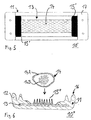
- FIG. 5 shows a modified grounding clamp 10 'in plan view shown, which has two tabs 15 'as holding means, into which the Ends of the contact element 14 are inserted for fixation.
- the tabs are preferably made of metal and are attached to the metal band Earthing clamp attached, for example by spot welding or gluing, the adhesive should be electrically conductive.
- This embodiment with insertion tabs 15 ' causes a particularly in the circumferential direction Grounding clamp of the contact element stably executed.
- the insertion and removal of the contact means is very easy to handle, so that assembly work is simplified.
- metal mandrels 15 " are used as holding means. provided that firmly connected to the metal band 13 of the device 10 " are and from which the contact element 14 is impaled. That does one area-wide fixation and still allows a very variable Positioning of contact elements of any shape. To fix it can increase individual or all thorns through the contact means (Metal fabric hose 14) are inserted and their tips be bent. Individual elongated thorns can also be provided the tips of which only pierce the contact medium and are bent.
- the invention is particularly suitable for contacting and grounding Cables, in particular coaxial cables. But it can be used for grounding or contacting of metal pipes and the like can be used.
Landscapes
- Cable Accessories (AREA)
- Multi-Conductor Connections (AREA)
- Coupling Device And Connection With Printed Circuit (AREA)
- Electroplating Methods And Accessories (AREA)
- Control And Other Processes For Unpacking Of Materials (AREA)
- Discharging, Photosensitive Material Shape In Electrophotography (AREA)
Abstract
Description
- Fig. 1
- zeigt in Perspektivansicht ein erstes Ausführungsbeispiel der erfindungsgemäßen Vorrichtung in Form einer Erdungsschelle;
- Fig. 2a
- zeigt im Querschnitt den Aufbau der Erdungsschelle im demontierten Zustand;
- Fig. 2b
- zeigt im Querschnitt den Aufbau der Erdungsschelle im montierten und kontaktierenden Zustand;
- Fig. 3
- zeigt den Aufbau der Erdungsschelle in einer Draufsicht;
- Fig. 4
- zeigt in Perspektivansicht die an einem Koaxialkabel befestigte Erdungsschelle;
- Fig. 5
- zeigt in der Draufsicht den Aufbau einer Erdungsschelle gemäß einem zweiten Ausführungsbeispiel; und
- Fig. 6
- zeigt im Querschnitt den Aufbau einer Erdungsschelle gemäß einem dritten Ausführungsbeispiel.
Claims (10)
- Vorrichtung (10) zum elektrisch leitenden Kontaktieren eines an seiner Oberfläche elektrisch leitenden Gegenstands (20), insbesondere eines Metallrohres oder eines elektrischen Kabels, bei dem die Vorrichtung (10) einen Grundkörper (11) hat, der isolierendes Material (12) und ein darin teilweise eingebettetes Metallteil (13) umfasst, und an dem ein Kontaktelement (14) angeordnet ist zur Herstellung einer elektrisch leitendenden Verbindung des Metallteils (13) mit dem zu kontaktierenden Gegenstand (20), wobei das Kontaktelement (14) sich an der dem zu kontaktierenden Gegenstand (20) zugewandten Innenseite des Grundkörpers (11) befindet, und bei dem die Vorrichtung (10) mindestens ein Halteteil (15) hat zur Fixierung des Kontaktelements (14) an dem Grundkörper (11),
dadurch gekennzeichnet, dass
das mindestens eine Halteteil (15) aus Metall gefertigt ist und dass das Halteteil (15) an dem Metallteil (13) des Grundkörpers (11) befestigt ist. - Vorrichtung (10) nach Anspruch 1, dadurch gekennzeichnet, dass
das mindestens eine Halteteil (15) mittels einer Klebe- oder Schweißverbindung, insbesondere einer Punktschweißverbindung (15A), an dem Metallteil (13) befestigt ist. - Vorrichtung (10) nach Anspruch 1 oder 2, dadurch gekennzeichnet, dass
das mindestens eine Halteteil als biegsame Metallklammer (15) ausgebildet ist, deren Enden umgebogen sind und somit das Kontaktelement (14) fixieren. - Vorrichtung (10') nach Anspruch 1 oder 2, dadurch gekennzeichnet, dass
das mindestens eine Halteteil als Lasche (15') ausgebildet ist, die teilweise das Kontaktelement (14) aufnimmt. - Vorrichtung (10") nach Anspruch 1 oder 2, dadurch gekennzeichnet, dass
das mindestens eine Halteteil als Metalldorn (15") ausgebildet ist, auf den das Kontaktelement (14) aufgesteckt ist. - Vorrichtung nach Anspruch 1 bis 5, dadurch gekennzeichnet, dass
das Kontaktelement als Metallstreifen ausgebildet ist. - Vorrichtung (10) nach Anspruch 1 bis 5, dadurch gekennzeichnet, dass
das Kontaktelement (14) mittels eines leitenden Gewebeschlauch (14A) gefertigt ist. - Vorrichtung (10) nach Anspruch 7, dadurch gekennzeichnet, dass
in das Innere des leitenden Gewebeschlauchs (14) ein Formelement (14B) eingebracht ist. - Vorrichtung (10) nach Anspruch 8, dadurch gekennzeichnet, dass
das Formelement aus einem Drahtbündel, insbesondere aus Drahtlitze (14B), gebildet ist. - Vorrichtung (10) nach Anspruch 8, dadurch gekennzeichnet, dass
der Grundkörper als Manschette oder Erdungsschelle (11) ausgebildet ist, die den zu kontaktierenden Gegenstand (20) umschließt.
Priority Applications (3)
| Application Number | Priority Date | Filing Date | Title |
|---|---|---|---|
| AT02360236T ATE375608T1 (de) | 2002-08-09 | 2002-08-09 | Vorrichtung zum elektrisch leitenden kontaktieren |
| DE50211047T DE50211047D1 (de) | 2002-08-09 | 2002-08-09 | Vorrichtung zum elektrisch leitenden Kontaktieren |
| EP02360236A EP1389807B1 (de) | 2002-08-09 | 2002-08-09 | Vorrichtung zum elektrisch leitenden Kontaktieren |
Applications Claiming Priority (1)
| Application Number | Priority Date | Filing Date | Title |
|---|---|---|---|
| EP02360236A EP1389807B1 (de) | 2002-08-09 | 2002-08-09 | Vorrichtung zum elektrisch leitenden Kontaktieren |
Publications (2)
| Publication Number | Publication Date |
|---|---|
| EP1389807A1 true EP1389807A1 (de) | 2004-02-18 |
| EP1389807B1 EP1389807B1 (de) | 2007-10-10 |
Family
ID=30470340
Family Applications (1)
| Application Number | Title | Priority Date | Filing Date |
|---|---|---|---|
| EP02360236A Expired - Lifetime EP1389807B1 (de) | 2002-08-09 | 2002-08-09 | Vorrichtung zum elektrisch leitenden Kontaktieren |
Country Status (3)
| Country | Link |
|---|---|
| EP (1) | EP1389807B1 (de) |
| AT (1) | ATE375608T1 (de) |
| DE (1) | DE50211047D1 (de) |
Cited By (2)
| Publication number | Priority date | Publication date | Assignee | Title |
|---|---|---|---|---|
| EP1808935A1 (de) * | 2005-12-19 | 2007-07-18 | Alcatel Lucent | Erdungsanlage mit einem Gehäuse aus Kunststoff |
| WO2009004400A1 (en) * | 2007-07-02 | 2009-01-08 | Alcatel-Lucent | Device for electrically conductive contacting a pipe |
Citations (2)
| Publication number | Priority date | Publication date | Assignee | Title |
|---|---|---|---|---|
| US1910022A (en) * | 1931-05-22 | 1933-05-23 | Columbia Engineering And Man C | Bonding clamp |
| DE19841186A1 (de) * | 1998-07-30 | 2000-02-03 | Daume Karin | Einrichtung zum elektrisch leitenden Kontaktieren eines elektrisch leitenden Teiles eines insbesondere länglichen, bspw. im wesentlichen zylindrischen Körpers, bspw. eines Rohres oder eines Kabels |
-
2002
- 2002-08-09 AT AT02360236T patent/ATE375608T1/de not_active IP Right Cessation
- 2002-08-09 EP EP02360236A patent/EP1389807B1/de not_active Expired - Lifetime
- 2002-08-09 DE DE50211047T patent/DE50211047D1/de not_active Expired - Lifetime
Patent Citations (2)
| Publication number | Priority date | Publication date | Assignee | Title |
|---|---|---|---|---|
| US1910022A (en) * | 1931-05-22 | 1933-05-23 | Columbia Engineering And Man C | Bonding clamp |
| DE19841186A1 (de) * | 1998-07-30 | 2000-02-03 | Daume Karin | Einrichtung zum elektrisch leitenden Kontaktieren eines elektrisch leitenden Teiles eines insbesondere länglichen, bspw. im wesentlichen zylindrischen Körpers, bspw. eines Rohres oder eines Kabels |
Cited By (5)
| Publication number | Priority date | Publication date | Assignee | Title |
|---|---|---|---|---|
| EP1808935A1 (de) * | 2005-12-19 | 2007-07-18 | Alcatel Lucent | Erdungsanlage mit einem Gehäuse aus Kunststoff |
| US7414198B2 (en) | 2005-12-19 | 2008-08-19 | Alcatel | Grounding device with plastic housing |
| WO2009004400A1 (en) * | 2007-07-02 | 2009-01-08 | Alcatel-Lucent | Device for electrically conductive contacting a pipe |
| US8052490B2 (en) | 2007-07-02 | 2011-11-08 | Alcatel Lucent | Device for electrically conductive contacting a pipe |
| CN101689714B (zh) * | 2007-07-02 | 2013-02-20 | 阿尔卡特朗讯 | 用于管的导电接触的设备 |
Also Published As
| Publication number | Publication date |
|---|---|
| EP1389807B1 (de) | 2007-10-10 |
| DE50211047D1 (de) | 2007-11-22 |
| ATE375608T1 (de) | 2007-10-15 |
Similar Documents
| Publication | Publication Date | Title |
|---|---|---|
| EP1295362B1 (de) | Elektrisch leitende rohr- oder kabelschelle | |
| DE10354288B4 (de) | Abgeschirmte Verdrahtung | |
| EP0982524B1 (de) | Einrichtung zum elektrisch leitenden Kontaktieren eines elektrisch leitenden Teiles eines insbesondere länglichen, beispielweise im wesentlichen zylindrischen Körpers, beispielsweise eines Rohres oder eines Kabels | |
| EP2647093B1 (de) | Haltevorrichtung zum halten eines kabels | |
| DE10310149A1 (de) | Abgeschirmtes Kabel | |
| EP2917972B1 (de) | Erdungsvorrichtung für den elektrisch leitfähigen mantel eines kabels und verfahren zum anbringen der erdungsvorrichtung | |
| DE102009055641A1 (de) | Elektrische Kontaktierungseinrichtung für Leitung und Abschirmung | |
| DE19841186A1 (de) | Einrichtung zum elektrisch leitenden Kontaktieren eines elektrisch leitenden Teiles eines insbesondere länglichen, bspw. im wesentlichen zylindrischen Körpers, bspw. eines Rohres oder eines Kabels | |
| EP1796216B1 (de) | Kabelschuh | |
| DE102008019165A1 (de) | Kabelverschraubung, insbesondere für ein Abschirm- oder Erdungskabel | |
| DE102004019689B3 (de) | Verfahren und Vorrichtung zum Kontaktieren eines leitenden Außenleiters eines Koaxialkabels | |
| EP1252685B1 (de) | Elektrisch leitende rohr- oder kabelschelle | |
| EP1389807B1 (de) | Vorrichtung zum elektrisch leitenden Kontaktieren | |
| CH666373A5 (de) | Waermeuebertrager und kabel-anschluss mit einem waermeuebertrager. | |
| DE19939331A1 (de) | Einrichtung zum elektrisch leitenden Kontaktieren eines elektrisch leitenden Teiles eines insbesondere länglichen, beispielsweise im wesentlichen zylindrischen Körpers, beispielsweise eines Rohres oder eines Kabels | |
| DE2456430C3 (de) | Lötfreie Yerbindungsbaugruppe | |
| DE19922856A1 (de) | Einrichtung zum elektrisch leitenden Kontaktieren eines elektrisch leitenden Teiles eines insbesondere länglichen, beispielsweise im wesentlichen zylindrischen Körpers, beispielsweise eines Rohres oder eines Kabels | |
| DE3131274C2 (de) | Erdverbindung für Schichtenmantel oder dgl. eines elektrischen Kabels | |
| WO2000015996A1 (de) | Elektrisch leitende rohr- oder kabelschelle | |
| DE2519053C3 (de) | Außenleiter-Anschlußeinrichtung für Koaxialkabel | |
| DE10031101A1 (de) | Einrichtung zum elektrisch leitenden Kontaktieren eines elektrisch leitenden Teiles eines insbesondere länglichen, beispielsweise im wesentlichen Zylindrischen Körpers, beispielsweise eines Rohres oder eines Kabels | |
| EP1289068B1 (de) | Einrichtung zum elektrisch leitenden Kontaktieren eines abschnittweise abisolierten Aussenleiters eines Koaxialkabels | |
| EP1356546B1 (de) | Einrichtung zum elektrisch leitenden kontaktieren eines abschnittsweise abisolierten aussenleiters eines koaxialkabels | |
| DE10004671B4 (de) | Einrichtung zum elektrisch leitenden Kontaktieren eines elektrisch leitenden Teiles eines insbesondere länglichen, beispielsweise im wesentlichen zylindrischen Körpers, beispielsweise eines Rohres oder eines Kabels | |
| EP1255321A1 (de) | Einrichtung zum elektrisch leitenden Kontaktieren eines abschnittsweise abisolierten Aussenleiters eines Koaxialkabels |
Legal Events
| Date | Code | Title | Description |
|---|---|---|---|
| PUAI | Public reference made under article 153(3) epc to a published international application that has entered the european phase |
Free format text: ORIGINAL CODE: 0009012 |
|
| 17P | Request for examination filed |
Effective date: 20021203 |
|
| AK | Designated contracting states |
Kind code of ref document: A1 Designated state(s): AT BE BG CH CY CZ DE DK EE ES FI FR GB GR IE IT LI LU MC NL PT SE SK TR |
|
| AX | Request for extension of the european patent |
Extension state: AL LT LV MK RO SI |
|
| AKX | Designation fees paid | ||
| RBV | Designated contracting states (corrected) |
Designated state(s): AT BE BG CH CY CZ DE DK EE ES FI FR GB GR IE IT LI LU MC NL PT SE SK TR |
|
| REG | Reference to a national code |
Ref country code: DE Ref legal event code: 8566 |
|
| 17Q | First examination report despatched |
Effective date: 20060823 |
|
| 17Q | First examination report despatched |
Effective date: 20060823 |
|
| GRAP | Despatch of communication of intention to grant a patent |
Free format text: ORIGINAL CODE: EPIDOSNIGR1 |
|
| RAP1 | Party data changed (applicant data changed or rights of an application transferred) |
Owner name: ALCATEL LUCENT |
|
| GRAS | Grant fee paid |
Free format text: ORIGINAL CODE: EPIDOSNIGR3 |
|
| GRAA | (expected) grant |
Free format text: ORIGINAL CODE: 0009210 |
|
| AK | Designated contracting states |
Kind code of ref document: B1 Designated state(s): AT BE BG CH CY CZ DE DK EE ES FI FR GB GR IE IT LI LU MC NL PT SE SK TR |
|
| REG | Reference to a national code |
Ref country code: GB Ref legal event code: FG4D Free format text: NOT ENGLISH |
|
| REG | Reference to a national code |
Ref country code: CH Ref legal event code: EP |
|
| REG | Reference to a national code |
Ref country code: IE Ref legal event code: FG4D Free format text: LANGUAGE OF EP DOCUMENT: GERMAN |
|
| REF | Corresponds to: |
Ref document number: 50211047 Country of ref document: DE Date of ref document: 20071122 Kind code of ref document: P |
|
| GBT | Gb: translation of ep patent filed (gb section 77(6)(a)/1977) |
Effective date: 20071212 |
|
| NLV1 | Nl: lapsed or annulled due to failure to fulfill the requirements of art. 29p and 29m of the patents act | ||
| PG25 | Lapsed in a contracting state [announced via postgrant information from national office to epo] |
Ref country code: SE Free format text: LAPSE BECAUSE OF FAILURE TO SUBMIT A TRANSLATION OF THE DESCRIPTION OR TO PAY THE FEE WITHIN THE PRESCRIBED TIME-LIMIT Effective date: 20080110 Ref country code: NL Free format text: LAPSE BECAUSE OF FAILURE TO SUBMIT A TRANSLATION OF THE DESCRIPTION OR TO PAY THE FEE WITHIN THE PRESCRIBED TIME-LIMIT Effective date: 20071010 Ref country code: ES Free format text: LAPSE BECAUSE OF FAILURE TO SUBMIT A TRANSLATION OF THE DESCRIPTION OR TO PAY THE FEE WITHIN THE PRESCRIBED TIME-LIMIT Effective date: 20080121 |
|
| ET | Fr: translation filed | ||
| PG25 | Lapsed in a contracting state [announced via postgrant information from national office to epo] |
Ref country code: PT Free format text: LAPSE BECAUSE OF FAILURE TO SUBMIT A TRANSLATION OF THE DESCRIPTION OR TO PAY THE FEE WITHIN THE PRESCRIBED TIME-LIMIT Effective date: 20080310 Ref country code: BG Free format text: LAPSE BECAUSE OF FAILURE TO SUBMIT A TRANSLATION OF THE DESCRIPTION OR TO PAY THE FEE WITHIN THE PRESCRIBED TIME-LIMIT Effective date: 20080110 |
|
| REG | Reference to a national code |
Ref country code: IE Ref legal event code: FD4D |
|
| PG25 | Lapsed in a contracting state [announced via postgrant information from national office to epo] |
Ref country code: CZ Free format text: LAPSE BECAUSE OF FAILURE TO SUBMIT A TRANSLATION OF THE DESCRIPTION OR TO PAY THE FEE WITHIN THE PRESCRIBED TIME-LIMIT Effective date: 20071010 Ref country code: DK Free format text: LAPSE BECAUSE OF FAILURE TO SUBMIT A TRANSLATION OF THE DESCRIPTION OR TO PAY THE FEE WITHIN THE PRESCRIBED TIME-LIMIT Effective date: 20071010 |
|
| PLBE | No opposition filed within time limit |
Free format text: ORIGINAL CODE: 0009261 |
|
| STAA | Information on the status of an ep patent application or granted ep patent |
Free format text: STATUS: NO OPPOSITION FILED WITHIN TIME LIMIT |
|
| PG25 | Lapsed in a contracting state [announced via postgrant information from national office to epo] |
Ref country code: SK Free format text: LAPSE BECAUSE OF FAILURE TO SUBMIT A TRANSLATION OF THE DESCRIPTION OR TO PAY THE FEE WITHIN THE PRESCRIBED TIME-LIMIT Effective date: 20071010 |
|
| 26N | No opposition filed |
Effective date: 20080711 |
|
| PG25 | Lapsed in a contracting state [announced via postgrant information from national office to epo] |
Ref country code: IE Free format text: LAPSE BECAUSE OF FAILURE TO SUBMIT A TRANSLATION OF THE DESCRIPTION OR TO PAY THE FEE WITHIN THE PRESCRIBED TIME-LIMIT Effective date: 20071010 |
|
| PG25 | Lapsed in a contracting state [announced via postgrant information from national office to epo] |
Ref country code: GR Free format text: LAPSE BECAUSE OF FAILURE TO SUBMIT A TRANSLATION OF THE DESCRIPTION OR TO PAY THE FEE WITHIN THE PRESCRIBED TIME-LIMIT Effective date: 20080111 |
|
| PG25 | Lapsed in a contracting state [announced via postgrant information from national office to epo] |
Ref country code: FI Free format text: LAPSE BECAUSE OF FAILURE TO SUBMIT A TRANSLATION OF THE DESCRIPTION OR TO PAY THE FEE WITHIN THE PRESCRIBED TIME-LIMIT Effective date: 20071010 |
|
| PG25 | Lapsed in a contracting state [announced via postgrant information from national office to epo] |
Ref country code: MC Free format text: LAPSE BECAUSE OF NON-PAYMENT OF DUE FEES Effective date: 20080831 |
|
| REG | Reference to a national code |
Ref country code: CH Ref legal event code: PL |
|
| PG25 | Lapsed in a contracting state [announced via postgrant information from national office to epo] |
Ref country code: EE Free format text: LAPSE BECAUSE OF FAILURE TO SUBMIT A TRANSLATION OF THE DESCRIPTION OR TO PAY THE FEE WITHIN THE PRESCRIBED TIME-LIMIT Effective date: 20071010 |
|
| PG25 | Lapsed in a contracting state [announced via postgrant information from national office to epo] |
Ref country code: LI Free format text: LAPSE BECAUSE OF NON-PAYMENT OF DUE FEES Effective date: 20080831 Ref country code: CH Free format text: LAPSE BECAUSE OF NON-PAYMENT OF DUE FEES Effective date: 20080831 |
|
| PG25 | Lapsed in a contracting state [announced via postgrant information from national office to epo] |
Ref country code: CY Free format text: LAPSE BECAUSE OF FAILURE TO SUBMIT A TRANSLATION OF THE DESCRIPTION OR TO PAY THE FEE WITHIN THE PRESCRIBED TIME-LIMIT Effective date: 20071010 Ref country code: BE Free format text: LAPSE BECAUSE OF NON-PAYMENT OF DUE FEES Effective date: 20080831 |
|
| PG25 | Lapsed in a contracting state [announced via postgrant information from national office to epo] |
Ref country code: AT Free format text: LAPSE BECAUSE OF NON-PAYMENT OF DUE FEES Effective date: 20080809 |
|
| PG25 | Lapsed in a contracting state [announced via postgrant information from national office to epo] |
Ref country code: LU Free format text: LAPSE BECAUSE OF NON-PAYMENT OF DUE FEES Effective date: 20080809 |
|
| PG25 | Lapsed in a contracting state [announced via postgrant information from national office to epo] |
Ref country code: TR Free format text: LAPSE BECAUSE OF FAILURE TO SUBMIT A TRANSLATION OF THE DESCRIPTION OR TO PAY THE FEE WITHIN THE PRESCRIBED TIME-LIMIT Effective date: 20071010 |
|
| PG25 | Lapsed in a contracting state [announced via postgrant information from national office to epo] |
Ref country code: IT Free format text: LAPSE BECAUSE OF NON-PAYMENT OF DUE FEES Effective date: 20080831 |
|
| REG | Reference to a national code |
Ref country code: GB Ref legal event code: 732E Free format text: REGISTERED BETWEEN 20130926 AND 20131002 |
|
| REG | Reference to a national code |
Ref country code: FR Ref legal event code: GC Effective date: 20131018 |
|
| REG | Reference to a national code |
Ref country code: FR Ref legal event code: RG Effective date: 20141016 |
|
| REG | Reference to a national code |
Ref country code: FR Ref legal event code: CA Effective date: 20150521 |
|
| REG | Reference to a national code |
Ref country code: FR Ref legal event code: CA Effective date: 20150521 |
|
| REG | Reference to a national code |
Ref country code: FR Ref legal event code: PLFP Year of fee payment: 14 |
|
| REG | Reference to a national code |
Ref country code: FR Ref legal event code: PLFP Year of fee payment: 15 |
|
| REG | Reference to a national code |
Ref country code: FR Ref legal event code: PLFP Year of fee payment: 16 |
|
| REG | Reference to a national code |
Ref country code: FR Ref legal event code: PLFP Year of fee payment: 17 |
|
| PGFP | Annual fee paid to national office [announced via postgrant information from national office to epo] |
Ref country code: FR Payment date: 20180827 Year of fee payment: 17 Ref country code: DE Payment date: 20180823 Year of fee payment: 17 |
|
| PGFP | Annual fee paid to national office [announced via postgrant information from national office to epo] |
Ref country code: GB Payment date: 20180822 Year of fee payment: 17 |
|
| REG | Reference to a national code |
Ref country code: DE Ref legal event code: R119 Ref document number: 50211047 Country of ref document: DE |
|
| GBPC | Gb: european patent ceased through non-payment of renewal fee |
Effective date: 20190809 |
|
| PG25 | Lapsed in a contracting state [announced via postgrant information from national office to epo] |
Ref country code: FR Free format text: LAPSE BECAUSE OF NON-PAYMENT OF DUE FEES Effective date: 20190831 Ref country code: DE Free format text: LAPSE BECAUSE OF NON-PAYMENT OF DUE FEES Effective date: 20200303 |
|
| PG25 | Lapsed in a contracting state [announced via postgrant information from national office to epo] |
Ref country code: GB Free format text: LAPSE BECAUSE OF NON-PAYMENT OF DUE FEES Effective date: 20190809 |