EP1389712A2 - Aufhängevorrichtung für eine Leuchte - Google Patents
Aufhängevorrichtung für eine Leuchte Download PDFInfo
- Publication number
- EP1389712A2 EP1389712A2 EP03018295A EP03018295A EP1389712A2 EP 1389712 A2 EP1389712 A2 EP 1389712A2 EP 03018295 A EP03018295 A EP 03018295A EP 03018295 A EP03018295 A EP 03018295A EP 1389712 A2 EP1389712 A2 EP 1389712A2
- Authority
- EP
- European Patent Office
- Prior art keywords
- lamp
- lamp housing
- suspension device
- bracket
- luminaire
- Prior art date
- Legal status (The legal status is an assumption and is not a legal conclusion. Google has not performed a legal analysis and makes no representation as to the accuracy of the status listed.)
- Withdrawn
Links
Images




Classifications
-
- F—MECHANICAL ENGINEERING; LIGHTING; HEATING; WEAPONS; BLASTING
- F21—LIGHTING
- F21S—NON-PORTABLE LIGHTING DEVICES; SYSTEMS THEREOF; VEHICLE LIGHTING DEVICES SPECIALLY ADAPTED FOR VEHICLE EXTERIORS
- F21S8/00—Lighting devices intended for fixed installation
- F21S8/04—Lighting devices intended for fixed installation intended only for mounting on a ceiling or the like overhead structures
- F21S8/06—Lighting devices intended for fixed installation intended only for mounting on a ceiling or the like overhead structures by suspension
-
- F—MECHANICAL ENGINEERING; LIGHTING; HEATING; WEAPONS; BLASTING
- F21—LIGHTING
- F21V—FUNCTIONAL FEATURES OR DETAILS OF LIGHTING DEVICES OR SYSTEMS THEREOF; STRUCTURAL COMBINATIONS OF LIGHTING DEVICES WITH OTHER ARTICLES, NOT OTHERWISE PROVIDED FOR
- F21V21/00—Supporting, suspending, or attaching arrangements for lighting devices; Hand grips
- F21V21/10—Pendants, arms, or standards; Fixing lighting devices to pendants, arms, or standards
- F21V21/112—Fixing lighting devices to pendants
-
- F—MECHANICAL ENGINEERING; LIGHTING; HEATING; WEAPONS; BLASTING
- F21—LIGHTING
- F21V—FUNCTIONAL FEATURES OR DETAILS OF LIGHTING DEVICES OR SYSTEMS THEREOF; STRUCTURAL COMBINATIONS OF LIGHTING DEVICES WITH OTHER ARTICLES, NOT OTHERWISE PROVIDED FOR
- F21V21/00—Supporting, suspending, or attaching arrangements for lighting devices; Hand grips
- F21V21/14—Adjustable mountings
- F21V21/16—Adjustable mountings using wires or cords
-
- F—MECHANICAL ENGINEERING; LIGHTING; HEATING; WEAPONS; BLASTING
- F21—LIGHTING
- F21Y—INDEXING SCHEME ASSOCIATED WITH SUBCLASSES F21K, F21L, F21S and F21V, RELATING TO THE FORM OR THE KIND OF THE LIGHT SOURCES OR OF THE COLOUR OF THE LIGHT EMITTED
- F21Y2103/00—Elongate light sources, e.g. fluorescent tubes
Definitions
- the invention relates to a suspension device for a lamp, especially a pendant lamp, for attachment to a Developers.
- the lamp preferably has a channel-like Luminaire housing for holding electrical components, such as electronic ones Ballasts, terminals and the like, and a connectable to the lamp housing and at least partially translucent element.
- the translucent Element can be, for example, a light directing profile or simple Luminaire cover to be formed.
- the lamp housing can e.g. made of extruded aluminum manufactured exist, with which this a high bending and torsional streak having.
- the translucent element is either designed as a plastic element or glass element. In the event of so-called "lighting technology” preferably come from plastic Plastics for use such. B. polycarbonate or PMMA. Essentially, these are amorphous, translucent Plastics, through which the one from the Luminaire arranged lamp passes emitted luminous flux.
- a prism structure on the surface for example a diffused but directed light. That too is Combination of a direct light component and an indirect one Share of light through appropriate light control from the lamp emitted luminous flux possible.
- the lights are offered in different wattages, so that different sized electronic ballasts (Electronic ballasts) are required. Because of the geometric Training the lamp, it is not always possible, this relative heavy ECGs to be placed in the center, so that the result is tilting moments act on the central axis of the lamp in the suspension. Tolerance differences in the lamp housing can also cause unwanted tilting moments. Usually this is assumed that the focus of such pendant lights due to of tolerance differences and differently arranged heavy electrical components between 60 and 100 mm fluctuates.
- Such a lamp is usually suspended with a formed as a wire rope hanging device that on a Property developer, e.g. a blanket. Because of the different The lamp is usually tilted by means of a so-called triangle suspension attached to the ceiling. This consists of a wire rope hanging from the ceiling with a fixing device provided at the end. This fixation device takes on another rope without slipping, its two Ends are attached to the lamp housing on both sides to implement a straight suspension of the lamp. Accordingly a total of four fastening points of the rope on the lamp housing required, two on each side of the luminaire housing.
- the light directing profile can take place. Because such a lamp has a weight of several kilos can and EN 60598 requires the strength of the workpieces, that a load of five times the lamp mass withstands, the wire rope ends cannot simply immediately attached to the plastic or glass, but must with reinforcement profiles in the form of shims that provide a widened contact surface. These reinforcement profiles produce in the plastic or Glass element an undesirable shadow formation in the transparent Surface that is unacceptable for design reasons is.
- the invention is therefore based on the technical problem to further develop a generic pendant lamp in such a way that undesirable shadows on transparent luminaire housing elements be avoided, even if an attachment the rope ends in the area of these elements is required to to enable a straight alignment of the lamp.
- the Suspension device is designed as a cantilever-shaped bracket, the one attached to the lamp housing mounting end and has a free end protruding from the lamp.
- the rope ends are attached to the attachment ends preferably by means of known thimbles, which in a corresponding Recording the bracket can be hooked.
- the suspension device according to the invention makes it possible for the first time hanging asymmetrical lights without creating a shadow Fastening element in the light guide element made of plastic or glass must be arranged.
- the focus is one such light more towards the heavier Luminaire housing located and requires an attachment point for the rope end also above the translucent light control profile.
- the suspension device according to the invention can be the second attachment point for the rope just above of the translucent lamp housing element can be arranged.
- the luminaire can have two leaves be formed, with light directing profiles on both sides a centrally arranged lamp housing are attached.
- the bracket is preferably designed so that the Free end in installation position close to the surface of the translucent Luminaire housing element adjoins.
- the attachment end of the bracket on the lamp housing can also be rotatable so that the bracket to simplify the Access to components within the light control profile from the side is pivotable. For example, this is the case for the Inserting a fluorescent lamp inside the light directing element or for the replacement of electronic ballasts inside the luminaire housing.
- a locking device is preferably provided with which the bracket can be fixed in different target positions.
- the Locking device can, for example, as a spring-loaded ball catch be designed.
- bracket can be adapted to various types trained luminaires and reduction of storage costs be telescopic.
- the lamp consists essentially of a lamp housing designated in its entirety with 1 and a laterally attached to this light guide profile 2.
- Das Luminaire housing 1 is closed on both sides by head pieces 11.
- FIG. 2 shows a cross section through the head piece 11 of the Luminaire housing 1.
- the head pieces provided on both sides 11 of the lamp housing 1 are corresponding stiffening ribs provided to the required torsional rigidity of the im to realize essential channel-like lamp housing 1.
- the lamp housing 1 itself is by a removable housing cover 12 closed.
- the electronic components such as ballasts, connection terminals and the like.
- the light guide profile 2 has a substantially wing-shaped Shape with an arcuate portion 21 on which a one-sided wing slightly arched upwards 22 is integrally formed.
- the lower end of the arcuate Section 21 is with a circular arc segment 23 in a notch depression of the aluminum profile 4 used.
- the wing 22 is on the top by a detachable, snap-on cover 24 closed to form a hollow chamber profile.
- the arcuate portion 21, wing 22 and cover 24 are made of optical engineering plastic and are therefore translucent for the one arranged in the sockets 5 Fluorescent lamp produces light. Part of the light kicks in through the arcuate section 21 as a direct light component below and another part through the wing 22 as an indirect Light portion from the side of the lamp.
- the Luminaire with a so-called triangle suspension on a ceiling attached This triangle suspension consists of a vertical one hanging rope 6 hanging from the ceiling has a fastening element 7 at its lower end.
- This Fastening element 7 is used to hold a non-slip Assembly rope 8.
- Cable thimbles 81 attached on both sides in corresponding recesses of bracket 9 attached to the lamp housing 1 are attachable.
- the bracket 9 has a connectable to the lamp housing 1 Fastening end 91 and one not with the lamp housing 1 connectable free end 92.
- the bracket 9 is in the present Embodiment in the form of a cantilever arm, one to the Luminaire housing 1 has adapted curvature so that this in the installed position fits harmoniously on the top of the lamp.
- the bracket 9 is connected to the head piece 11 by means of a screw 10 of the lamp housing 1 screwed in a cylindrical Foot 93 is sunk with a through opening of the bracket 9.
- the head pieces 11 there are known ball catches in their mode of operation 13 provided in the installed position by a spring 94 press against the underside of foot 93 on the underside.
- the coat hanger 9 has trained corresponding to the ball catches 13 hemispherical recesses 95 into which the ball of Ball catches 13 for fixing in the corresponding target position can be pressed in.
- bracket 9 in the assembly position, in which the free end on the right side of the center of gravity 12 lies.
- the mounting end is in the installed position 91 and the free end 92 to the right and left of that Luminaire focus 12, as to ensure a defined Suspension of the center of gravity between the attachment points the rope suspension must lie.
- the bracket 9 spanned in other words, those in the area of the unstable plastic element Luminaire focus 12. Therefore, in the plastic element no fastener may be provided.
Landscapes
- Engineering & Computer Science (AREA)
- General Engineering & Computer Science (AREA)
- Non-Portable Lighting Devices Or Systems Thereof (AREA)
- Fastening Of Light Sources Or Lamp Holders (AREA)
- Securing Globes, Refractors, Reflectors Or The Like (AREA)
Abstract
Description
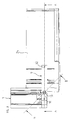
- Fig. 1
- eine perspektivische Ansicht einer asymmetrischen Leuchte mit der erfindungsgemäßen Aufhängevorrichtung,
- Fig. 2
- einen Querschnitt durch das Kopfende der Leuchte entlang der Linie A-A gemäß Fig. 3,
- Fig. 3
- eine detaillierte Draufsicht des erfindungsgemäßen Bügels in Einbaulage,
- Fig. 4
- eine Draufsicht des Bügels gemäß Figur 3 in gedrehter Stellung
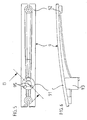
- Fig. 5
- eine Draufsicht des Bügels,
- Fig. 6
- eine Seitenansicht des Bügels gemäß Fig. 5 und
- Fig. 7
- ein Schnitt entlang der Linie B-B gemäß Fig. 5 zur Darstellung der Befestigung des Bügels am Leuchtengehäuse.
- 1
- Leuchtengehäuse
- 11
- Kopfstück
- 12
- Gehäuseabdeckung
- 2
- Lichtlenkprofil
- 21
- bogenförmiger Abschnitt
- 22
- Flügel
- 23
- Kreisbogensegment
- 24
- Abdeckung
- 4
- Aluminiumprofil
- 5
- Fassung
- 6
- Befestigungsseil
- 7
- Befestigungselement
- 8
- Montageseil
- 81
- Seilkausche
- 9
- Bügel
- 91
- Befestigungsende
- 92
- Freiende
- 93
- Fuß
- 94
- Feder
- 95
- Ausnehmung
- 12
- Leuchtenschwerpunkt
- 13
- Kugelraste
Claims (7)
- Aufhängevorrichtung zur Befestigung einer Leuchte an einem Bauträger mittels einer Aufhängevorrichtung, wobei die Leuchte ein Leuchtengehäuse (1) zur Aufnahme elektrischer Bauelemente und ein mit dem Leuchtengehäuse verbindbares und zumindest teilweise lichtdurchlässiges Leuchtengehäuseelement aufweist, dadurch gekennzeichnet, dass die Aufhängevorrichtung einen Bügel (9) mit einem an dem Leuchtengehäuse (1) befestigten Befestigungsende (91) und einem von der Leuchte abstehenden Freiende (92) aufweist.
- Aufhängevorrichtung nach Anspruch 1, dadurch gekennzeichnet, dass die Leuchte asymmetrisch ausgebildet ist.
- Aufhängevorrichtung nach einem der vorhergehenden Ansprüche, dadurch gekennzeichnet, dass das lichtdurchlässige Leuchtengehäuseelement als Leuchtenabdeckung oder Lichtlenkprofil (2) ausgebildet ist.
- Aufhängevorrichtung nach einem der vorhergehenden Ansprüche, dadurch gekennzeichnet, dass das Lichtlenkprofil (2) als mit dem Leuchtengehäuse (1) verbindbarer Flügel ausgebildet ist.
- Aufhängevorrichtung nach Anspruch 4, dadurch gekennzeichnet, dass der Flügel einseitig an dem Leuchtengehäuse (1) befestigt ist.
- Aufhängevorrichtung nach einem der vorhergehenden Ansprüche, dadurch gekennzeichnet, dass diese drehbar mit dem Leuchtengehäuse (1) verbunden ist.
- Aufhängevorrichtung nach Anspruch 5, gekennzeichnet durch eine Rastvorrichtung, mit welcher diese in verschiedenen Sollpositionen fixierbar ist.
Applications Claiming Priority (2)
| Application Number | Priority Date | Filing Date | Title |
|---|---|---|---|
| DE10237201A DE10237201B4 (de) | 2002-08-14 | 2002-08-14 | Aufhängevorrichtung für eine Leuchte |
| DE10237201 | 2002-08-14 |
Publications (2)
| Publication Number | Publication Date |
|---|---|
| EP1389712A2 true EP1389712A2 (de) | 2004-02-18 |
| EP1389712A3 EP1389712A3 (de) | 2006-05-31 |
Family
ID=30469737
Family Applications (1)
| Application Number | Title | Priority Date | Filing Date |
|---|---|---|---|
| EP03018295A Withdrawn EP1389712A3 (de) | 2002-08-14 | 2003-08-12 | Aufhängevorrichtung für eine Leuchte |
Country Status (2)
| Country | Link |
|---|---|
| EP (1) | EP1389712A3 (de) |
| DE (1) | DE10237201B4 (de) |
Family Cites Families (12)
| Publication number | Priority date | Publication date | Assignee | Title |
|---|---|---|---|---|
| US2173325A (en) * | 1936-02-24 | 1939-09-19 | American Sterilizer Co | Surgical operating luminaire |
| DE669399C (de) * | 1936-11-08 | 1938-12-23 | Schneider & Co Dr Ing | Litzenpendel mit mittels Klemmvorrichtung am Pendel in gewuenschter Hoehe aufhaengbarer Reflektorleuchte |
| DE863695C (de) * | 1951-10-28 | 1953-01-19 | Wilhelm Lenze K G | Vorrichtung zur Aufhaengung von Langfeldleuchten |
| DE1760905U (de) * | 1956-04-28 | 1958-02-06 | Quarzlampen Gmbh | Operationsleuchte. |
| DE3620920A1 (de) * | 1986-06-24 | 1988-01-14 | Kurth Egon Dipl Ing Designer | Niedervolt-leuchte |
| US5128848A (en) * | 1989-03-31 | 1992-07-07 | W.C. Heraeus Gmbh | Operating light |
| FR2685948B1 (fr) * | 1992-01-08 | 1994-03-18 | Zebulon | Dispositif d'eclairage et de suspension d'une cimaise et ensemble modulaire d'eclairage et de suspension de cimaises. |
| DE9209625U1 (de) * | 1992-07-17 | 1992-09-17 | Schnell, Helmut, Dipl.-Ing. (FH), 7200 Tuttlingen | Leuchte, insbesondere Büroleuchte |
| US5530628A (en) * | 1993-04-05 | 1996-06-25 | Peerless Lighting Corporation | Task light |
| DE29616280U1 (de) * | 1996-09-19 | 1996-11-28 | Deska, Rainer, 45549 Sprockhövel | Leuchte zur Beleuchtung von Hallen |
| DE20004889U1 (de) * | 2000-03-17 | 2000-05-18 | Spectral Gesellschaft für Lichttechnik mbH, 79111 Freiburg | Leuchte |
| CA2343565A1 (en) * | 2001-04-09 | 2002-10-09 | Spi Lighting, Inc. | Modular cluster lighting fixture |
-
2002
- 2002-08-14 DE DE10237201A patent/DE10237201B4/de not_active Expired - Fee Related
-
2003
- 2003-08-12 EP EP03018295A patent/EP1389712A3/de not_active Withdrawn
Also Published As
| Publication number | Publication date |
|---|---|
| EP1389712A3 (de) | 2006-05-31 |
| DE10237201B4 (de) | 2005-02-10 |
| DE10237201A1 (de) | 2004-03-04 |
Similar Documents
| Publication | Publication Date | Title |
|---|---|---|
| EP0898686B2 (de) | Leuchte mit einem basiskörper als träger für wenigstens eine lampe | |
| DE102009007308B4 (de) | Anbau- bzw. Wandleuchte | |
| EP0732540B1 (de) | Einbauleuchte mit Haltemitteln zu ihrer Halterung in einem Einbaukörper | |
| WO2004020900A1 (de) | Deckenleuchte mit einem länglichen leuchtengehäuse | |
| EP1495258B1 (de) | Flache leuchte | |
| EP0660036B1 (de) | Fassungsträger für eine Deckeneinbauleuchte | |
| EP0285627B1 (de) | Leuchtenanordnung mit zwischen zwei niederspannungs-stromleitern angeordneten leuchten | |
| DE10237201B4 (de) | Aufhängevorrichtung für eine Leuchte | |
| DE102018103575A1 (de) | Set zur Realisierung eines Einbaustrahlers | |
| DE10321282B4 (de) | Wandleuchte | |
| EP2107298B1 (de) | Langgestreckte Hängeleuchte | |
| DE2748606A1 (de) | Befestigungsvorrichtung fuer leuchten | |
| EP2146140B1 (de) | Verstellbare Leuchte | |
| DE102010028332A1 (de) | Anordnung zur Befestigung eines Gegenstandes an einem langgestreckten Aufhängungselement | |
| DE202010003758U1 (de) | Leuchte | |
| DE102004044024B4 (de) | Vorrichtung zur hängenden Anordung einer Leuchte | |
| DE202018101307U1 (de) | Seilleuchte für eine Straßenbeleuchtung | |
| DE10029405B4 (de) | Leuchte zum Anbringen an einen Träger | |
| DE102004016485A1 (de) | Leuchte mit einer variabel gestaltbaren Leuchtenabdeckung | |
| DE8706542U1 (de) | Deckeneinbauleuchte mit Energiesparlampe | |
| DE102004016817A1 (de) | Verbindungsmittel für Leuchtenelemente | |
| DE202013007923U1 (de) | Stableuchte mit Leuchtenhalter | |
| DE29707313U1 (de) | Leuchte zur indirekten Beleuchtung | |
| DE202006002514U1 (de) | Außenleuchte mit einem Leuchtengehäuse mit zwei mastseitigen Öffnungen | |
| AT388431B (de) | Leuchtstofflampenleuchte |
Legal Events
| Date | Code | Title | Description |
|---|---|---|---|
| PUAI | Public reference made under article 153(3) epc to a published international application that has entered the european phase |
Free format text: ORIGINAL CODE: 0009012 |
|
| AK | Designated contracting states |
Kind code of ref document: A2 Designated state(s): AT BE BG CH CY CZ DE DK EE ES FI FR GB GR HU IE IT LI LU MC NL PT RO SE SI SK TR |
|
| AX | Request for extension of the european patent |
Extension state: AL LT LV MK |
|
| PUAL | Search report despatched |
Free format text: ORIGINAL CODE: 0009013 |
|
| AK | Designated contracting states |
Kind code of ref document: A3 Designated state(s): AT BE BG CH CY CZ DE DK EE ES FI FR GB GR HU IE IT LI LU MC NL PT RO SE SI SK TR |
|
| AX | Request for extension of the european patent |
Extension state: AL LT LV MK |
|
| 17P | Request for examination filed |
Effective date: 20061122 |
|
| AKX | Designation fees paid |
Designated state(s): AT BE BG CH CY CZ DE DK EE ES FI FR GB GR HU IE IT LI LU MC NL PT RO SE SI SK TR |
|
| 17Q | First examination report despatched |
Effective date: 20070327 |
|
| STAA | Information on the status of an ep patent application or granted ep patent |
Free format text: STATUS: THE APPLICATION IS DEEMED TO BE WITHDRAWN |
|
| 18D | Application deemed to be withdrawn |
Effective date: 20070807 |