EP1389685A2 - Steuerblock mit Logikventilen - Google Patents
Steuerblock mit Logikventilen Download PDFInfo
- Publication number
- EP1389685A2 EP1389685A2 EP03014194A EP03014194A EP1389685A2 EP 1389685 A2 EP1389685 A2 EP 1389685A2 EP 03014194 A EP03014194 A EP 03014194A EP 03014194 A EP03014194 A EP 03014194A EP 1389685 A2 EP1389685 A2 EP 1389685A2
- Authority
- EP
- European Patent Office
- Prior art keywords
- logic
- block
- tank
- control block
- pump
- Prior art date
- Legal status (The legal status is an assumption and is not a legal conclusion. Google has not performed a legal analysis and makes no representation as to the accuracy of the status listed.)
- Granted
Links
- 238000005266 casting Methods 0.000 claims description 6
- 238000004519 manufacturing process Methods 0.000 description 7
- 238000010276 construction Methods 0.000 description 4
- 238000010586 diagram Methods 0.000 description 3
- 238000009434 installation Methods 0.000 description 3
- 229910000831 Steel Inorganic materials 0.000 description 2
- 238000005553 drilling Methods 0.000 description 2
- 239000010959 steel Substances 0.000 description 2
- 238000011161 development Methods 0.000 description 1
- 230000018109 developmental process Effects 0.000 description 1
- 238000005516 engineering process Methods 0.000 description 1
- 239000000446 fuel Substances 0.000 description 1
- 239000000463 material Substances 0.000 description 1
- 230000001360 synchronised effect Effects 0.000 description 1
Images



Classifications
-
- F—MECHANICAL ENGINEERING; LIGHTING; HEATING; WEAPONS; BLASTING
- F15—FLUID-PRESSURE ACTUATORS; HYDRAULICS OR PNEUMATICS IN GENERAL
- F15B—SYSTEMS ACTING BY MEANS OF FLUIDS IN GENERAL; FLUID-PRESSURE ACTUATORS, e.g. SERVOMOTORS; DETAILS OF FLUID-PRESSURE SYSTEMS, NOT OTHERWISE PROVIDED FOR
- F15B13/00—Details of servomotor systems ; Valves for servomotor systems
- F15B13/02—Fluid distribution or supply devices characterised by their adaptation to the control of servomotors
- F15B13/06—Fluid distribution or supply devices characterised by their adaptation to the control of servomotors for use with two or more servomotors
- F15B13/08—Assemblies of units, each for the control of a single servomotor only
- F15B13/0803—Modular units
- F15B13/0807—Manifolds
- F15B13/0814—Monoblock manifolds
-
- F—MECHANICAL ENGINEERING; LIGHTING; HEATING; WEAPONS; BLASTING
- F15—FLUID-PRESSURE ACTUATORS; HYDRAULICS OR PNEUMATICS IN GENERAL
- F15B—SYSTEMS ACTING BY MEANS OF FLUIDS IN GENERAL; FLUID-PRESSURE ACTUATORS, e.g. SERVOMOTORS; DETAILS OF FLUID-PRESSURE SYSTEMS, NOT OTHERWISE PROVIDED FOR
- F15B11/00—Servomotor systems without provision for follow-up action; Circuits therefor
- F15B11/006—Hydraulic "Wheatstone bridge" circuits, i.e. with four nodes, P-A-T-B, and on-off or proportional valves in each link
-
- F—MECHANICAL ENGINEERING; LIGHTING; HEATING; WEAPONS; BLASTING
- F15—FLUID-PRESSURE ACTUATORS; HYDRAULICS OR PNEUMATICS IN GENERAL
- F15B—SYSTEMS ACTING BY MEANS OF FLUIDS IN GENERAL; FLUID-PRESSURE ACTUATORS, e.g. SERVOMOTORS; DETAILS OF FLUID-PRESSURE SYSTEMS, NOT OTHERWISE PROVIDED FOR
- F15B13/00—Details of servomotor systems ; Valves for servomotor systems
- F15B13/02—Fluid distribution or supply devices characterised by their adaptation to the control of servomotors
- F15B13/06—Fluid distribution or supply devices characterised by their adaptation to the control of servomotors for use with two or more servomotors
- F15B13/08—Assemblies of units, each for the control of a single servomotor only
- F15B13/0803—Modular units
- F15B13/0832—Modular valves
-
- F—MECHANICAL ENGINEERING; LIGHTING; HEATING; WEAPONS; BLASTING
- F15—FLUID-PRESSURE ACTUATORS; HYDRAULICS OR PNEUMATICS IN GENERAL
- F15B—SYSTEMS ACTING BY MEANS OF FLUIDS IN GENERAL; FLUID-PRESSURE ACTUATORS, e.g. SERVOMOTORS; DETAILS OF FLUID-PRESSURE SYSTEMS, NOT OTHERWISE PROVIDED FOR
- F15B13/00—Details of servomotor systems ; Valves for servomotor systems
- F15B13/02—Fluid distribution or supply devices characterised by their adaptation to the control of servomotors
- F15B13/06—Fluid distribution or supply devices characterised by their adaptation to the control of servomotors for use with two or more servomotors
- F15B13/08—Assemblies of units, each for the control of a single servomotor only
- F15B13/0803—Modular units
- F15B13/0871—Channels for fluid
-
- F—MECHANICAL ENGINEERING; LIGHTING; HEATING; WEAPONS; BLASTING
- F15—FLUID-PRESSURE ACTUATORS; HYDRAULICS OR PNEUMATICS IN GENERAL
- F15B—SYSTEMS ACTING BY MEANS OF FLUIDS IN GENERAL; FLUID-PRESSURE ACTUATORS, e.g. SERVOMOTORS; DETAILS OF FLUID-PRESSURE SYSTEMS, NOT OTHERWISE PROVIDED FOR
- F15B13/00—Details of servomotor systems ; Valves for servomotor systems
- F15B13/02—Fluid distribution or supply devices characterised by their adaptation to the control of servomotors
- F15B13/06—Fluid distribution or supply devices characterised by their adaptation to the control of servomotors for use with two or more servomotors
- F15B13/08—Assemblies of units, each for the control of a single servomotor only
- F15B13/0803—Modular units
- F15B13/0878—Assembly of modular units
- F15B13/0885—Assembly of modular units using valves combined with other components
- F15B13/0892—Valves combined with fluid components
-
- F—MECHANICAL ENGINEERING; LIGHTING; HEATING; WEAPONS; BLASTING
- F15—FLUID-PRESSURE ACTUATORS; HYDRAULICS OR PNEUMATICS IN GENERAL
- F15B—SYSTEMS ACTING BY MEANS OF FLUIDS IN GENERAL; FLUID-PRESSURE ACTUATORS, e.g. SERVOMOTORS; DETAILS OF FLUID-PRESSURE SYSTEMS, NOT OTHERWISE PROVIDED FOR
- F15B13/00—Details of servomotor systems ; Valves for servomotor systems
- F15B13/02—Fluid distribution or supply devices characterised by their adaptation to the control of servomotors
- F15B13/06—Fluid distribution or supply devices characterised by their adaptation to the control of servomotors for use with two or more servomotors
- F15B13/08—Assemblies of units, each for the control of a single servomotor only
- F15B13/0803—Modular units
- F15B13/0878—Assembly of modular units
- F15B13/0896—Assembly of modular units using different types or sizes of valves
-
- F—MECHANICAL ENGINEERING; LIGHTING; HEATING; WEAPONS; BLASTING
- F15—FLUID-PRESSURE ACTUATORS; HYDRAULICS OR PNEUMATICS IN GENERAL
- F15B—SYSTEMS ACTING BY MEANS OF FLUIDS IN GENERAL; FLUID-PRESSURE ACTUATORS, e.g. SERVOMOTORS; DETAILS OF FLUID-PRESSURE SYSTEMS, NOT OTHERWISE PROVIDED FOR
- F15B2211/00—Circuits for servomotor systems
- F15B2211/30—Directional control
- F15B2211/305—Directional control characterised by the type of valves
- F15B2211/3056—Assemblies of multiple valves
- F15B2211/30565—Assemblies of multiple valves having multiple valves for a single output member, e.g. for creating higher valve function by use of multiple valves like two 2/2-valves replacing a 5/3-valve
- F15B2211/30575—Assemblies of multiple valves having multiple valves for a single output member, e.g. for creating higher valve function by use of multiple valves like two 2/2-valves replacing a 5/3-valve in a Wheatstone Bridge arrangement (also half bridges)
Definitions
- the invention relates to a control block with logic valves according to the preamble of claim 1.
- Such control blocks are used, for example, for control purposes used by hydraulic cylinders, being used for control the pressure medium flow to and from the hydraulic cylinder Logic valves - or according to DIN standard: 2-way cartridge valves - are used.
- Such logic valves - also logic called - can have a path, current and / or pressure function take over and, with large production quantities, become Cost reduction instead of conventional conventional ones Elements, i.e. Way slide, locking, pressure and Current valves used.
- cylinders are at least 4 logic valves required over each pressure chamber with the pump (Pump logic) or connectable to the tank (tank logic) is.
- a control block is disclosed in US Pat. No. 5,975,134. where all connections and Channels are formed and the logic valves in separate Disks are used, which in turn come with the necessary pilot valves on the side walls of the central block.
- This solution has the same disadvantages as the solution described above, because the Channel routing in the central block is extremely complex.
- the invention is based on the object to create a control block with logic valves that is easy to manufacture.
- control block with a basic block executed, at least one pressure connection and a tank or return connection are formed.
- the Logic valves are over one or more block disks attached to the base block, with each block disc the associated consumer connection is designed.
- On such control block can be extremely simple Manufacture way, because the pressure and tank channels simply in the Basic block can be formed and the connection can be produced to the block disks by short connection channels is that already during the casting process or can be subsequently introduced by drilling.
- There the consumer connections each on a block washer are the piping on the connection side much easier than with the conventional monoblock construction.
- the basic block can in principle manufacture as a cast block and can be to Number of block disks to be applied from this cast block be cut off, so the delivery time of individually adapted solutions compared to conventional ones Solutions, each with its own new cast construction was essentially abbreviated can be.
- control block according to the invention is preferred to control a differential cylinder (but also different types of consumers), both the piston-side cylinder space as well as the piston rod-side Annulus one block disk each with is assigned to a tank and pump logic.
- the construction of the basic block is particularly simple, if the tank and pump channels run parallel and the corresponding connections open on the front.
- the amount is by two pump logic regardless of the direction of movement of the differential cylinder always the same.
- pressure medium supply in the cylinder space is according to the area ratio of the differential cylinder (e.g. two to one) only half of the space on the piston rod side Pressure medium quantity displaced, while with a pressure medium supply to the piston rod side space from the Cylinder space is displaced twice the amount.
- the valve sizes are optimized in the case of an inventive Proposed solution in which the piston rod side Unit assigned to the pressure chamber is the pump logic larger than the tank logic and the cylinder room assigned unit, the tank logic is larger than the pump logic perform.
- the tank channel has a larger effective cross section than the pump channel has.
- these two tank channels run in a parallel plane to a side surface and the pump channel in a central plane to that of the Tank channels spanned level is arranged.
- the basic block is approximately cuboid is, the tank and pump and possibly control connections preferably open at the front.
- the axis of a logic assigned to the pump connection in parallel and the Vertical axis of a logic assigned to the tank connection trained to the axis of the consumer connection.
- the axis of the consumer connection can also be used perpendicular to the axis of the pump logic and parallel to the The axis of the tank logic runs.
- the consumer connections can be made from the basic block facing away from the large surface of the block disc or to the Side surfaces are formed, the arrangement of the Consumer connection on the smaller side surface a cuboid block disk is preferred.
- the production of the basic block can be continued simplify when the tank and pump channels through at inserted pipes are formed during a casting process. Channels that are not required could then be channeled through Locking screws are blocked.
- connection channels are preferably at right angles to the parallel tank or pressure channels.
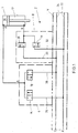
- FIG. 1 shows a circuit in a highly simplified form, in which a hydraulic cylinder 1 via a control block 2 with a pressure connection P or a tank connection T is connectable.
- the control block 2 has a basic block 4, on which several - in the following two examples - block disks 6, 8 are attached.
- the block disc 6 is a cylinder chamber 10 on the bottom and the block disk 8 a piston rod side annular space 12 of the in Differential design hydraulic cylinder 1 assigned.
- each block disc there is one to one of the pressure rooms 10, 12 leading consumer connections A and B are formed.
- Each of the block disks 6, 8 carries a pump logic 14 or 16 and a tank logic 18 or 20.
- the assigned pressure space 10 or 12 with a pump channel 22 and via each tank logic 18, 20 the assigned pressure chamber 12 or 10 with a tank channel 24 are connected.
- These two channels 22, 24 run in the basic block 4 and are connected to the logic 14, 18; 16 20 connected via connection channels 26, 28, 30, 32.
- the logic valves are, depending on the application, with different control covers for connecting each required pilot valves.
- FIG. 2 shows a three-dimensional representation of a Control block 2.
- the basic block 4 as a cuboid Cast block formed, on whose in Fig. 2nd visible end face 34 two interconnected Tank channels 24a, 24b and the pump channel 22 open, see above that on the front via corresponding connection diagrams Tank connection T or a pressure connection P is formed is. Furthermore, they are not shown in the basic block Control channels X, Y are provided.
- the channels 24a, 24b, 22 penetrate the basic block 4 at a parallel distance, the two tank channels 24a, 24b in a parallel to the rear side surface 36 Level are arranged, and one between the two Tank channels 24a, 24b arranged center plane the axis of the pump channel 22 intersects.
- connection channels (not shown) still several block disks 6,8 ... and other valve devices 44 - for example a valve arrangement for secondary movements, etc. - arranged.
- the block disks 6,8 and the valve devices 44 can practically on each of the side surfaces 36, 38, 40, 42 are attached.
- the Side surface 40 with a plurality of parallel to each other arranged, each a bottom-side pressure chamber a block disks 6 assigned to a cylinder while on one of the other side surfaces 38, 42 the block disks 8 on the piston rod side are fastened.
- Each side of the base block 4 can with block disks or Valves are occupied.
- the length L of the control block aligns depending on the number of block washers to be attached, with a basic block 4 with this length L after Cut off as needed from a pre-made cast block is formed in which at least the channels 22, 24 are.
- the logic valves of the circuit for example the pump logic 14 or 16 and the tank logic 18 or 20 used.
- the installation bores are to accommodate the main stages of the Block disc 6, 8 seated logic valves in the respective Block disc 6, 8 formed.
- the Block disc still other logic valves and others Valve devices for additional functions, for example to relieve the cylinder before lowering and Measuring points for the pumps and consumer connections wear.
- a special feature of the invention is that the consumer connections A, B also on the block washers 6 or 8 and not - as in the prior art together with the tank and pump connection in one Monoblock - are trained.
- the effective cross section of the two branch channels 24a, 24b existing tank channel 24 is essential selected larger than that of the pump channel 22.
- the tank logic 18 of the block disk 6 becomes pressurized with almost twice the cross-section as the pump logic 14 the block disk 6 assigned to the cylinder space 10 executed while the tank logic 20 of the annulus 12th assigned block disc 8 smaller than the assigned Pump logic 16 is executed.
- the tank logic has 18 the block disc 6 is the largest nominal size.
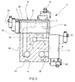
- FIG 3 is a section through a further embodiment a control block 2 shown.
- the block washers 6 vertically to the drawing level in Fig. 3 one behind the other on the Side surface 42 and the block disks 8 accordingly of the adjacent side surface 40 are arranged.
- these block disks 6, 8 each take a pump logic 14 or 16 and a tank logic 18 or 20. The main stage the pump logic is in a mounting hole 5 and Main stage of the tank logic in an installation hole 7 of the used block disk.
- the two are together connected tank channels 24a, 24b via the perpendicular to Side surface 40 extending connection channel 30 with the Output connection 46 of the tank logic 20 and via the Connection channel 28 with the output connection of the tank logic 18 connected.
- the pump channel 22 is via the connection channel 32 with the input connection 48 of the pump logic 16 the block disc 8 and via the connecting channel 26 with the input connection of the pump logic, not shown 14 of the block disk 6 connected.
- connection channels 26, 28; 30, 32 are the connection channels 26, 28; 30, 32 as perpendicular to the respective Side surfaces 40, 42 bores formed, so that they can easily be added to the prefabricated basic block 4 can be incorporated. Due to the triangular offset of the channels 24a, 24b, 22, the connection channels can be extremely easily without one Risk of overlap. at In large series blocks, it is also possible in principle Form connection channels immediately during the casting process.
- At least channels 24 and 22 are inserted by inserting Steel pipes formed so that after the casting process no drilling is required.
- the steel pipes are through Material bond held in the casting block and are designed that no glowing can take place.
- the channel guide is very clearly structured and easy to train, because then the axes of the tank logic 18, 20 parallel to the outer side surface of the Block disc 6, 8 - or in other words - run perpendicular to the axis of the connections A, B, while the axes of the pump logic 14, 16 perpendicular to the outer side faces or parallel or to the Connection axes are oriented, so that also in the Block disks 6, 8 formed sections of the connecting channels as well as the mounting holes for the logic valves very simple as being perpendicular to each other Bores can be formed.
- the consumer connections - A, B on the base block 4 Large surface 50 facing away from the block disks 6, 8.
- a disadvantage of the example in FIG. 2 solution shown is that the consumer connection A is relatively difficult to access because of this large area 50 of the block disk 6 already the pump logic 14 and one further valve device 52 are arranged.
- FIG. 5 shows a view of the embodiment according to Figure 4, wherein the block plate 6 is omitted.
- the drawn block disc 8 is the annular space 12 of the Cylinder 1 (see Figure 1) assigned. Accordingly, it is Pump logic 16 on the large area removed from base block 4 50 of the block disk 8 attached.
- the tank logic 20 is on the bottom surface 56 in FIG Block disc 8 arranged.
- the consumer connection B is provided on the opposite, upper end face 54, which is freely accessible, so that the assembly of the for Consumer leading lines compared to the above Solution is much easier.
- the exemplary embodiment is that leading to the pump channel 22 Connection channel 32 obliquely to that leading to the tank channel 24b Connection channel 30 turned on and opens into one Inlet channel 58 of the block disc 8.
- connection channel 30 opens into an inlet channel 60 on the tank connection side, via which the connection between the tank channel 24b and the mounting hole 7 of the tank logic 20 is made.
- the Structure of the block disc 6 is corresponding, the Working connection opens into the end face 56.
- the side Connection of the mounting hole 5 and the axial connection the installation hole 7 is an open fluidic connection, like this with the help of the dotted holes can be seen.
- the dimensions of the block disks 6, 8 are in the shown in Figure 4 different chosen, the dimensions and the connection diagrams of the Block disks 6, 8 are standardized, however, so that the control blocks by putting together several standardized basic modules (blocks 6, 8, basic block) in a simple way to the respective operating conditions Adjust (nominal sizes, number of consumers ...) to let.
- the prescribed control block 2 is used for control used by differential cylinders.
- control blocks for example synchronous cylinders, hydraulic motors or the like controllable.
- a control block for controlling a is disclosed Consumer, in particular a hydraulic cylinder, wherein in a base block at least one pressure and a tank or Return connection is formed. On the basic block is at least one block disc with at least one logic valve attached, with a consumer connection on the Block disc is formed.
Landscapes
- Engineering & Computer Science (AREA)
- Physics & Mathematics (AREA)
- Fluid Mechanics (AREA)
- Mechanical Engineering (AREA)
- General Engineering & Computer Science (AREA)
- Fluid-Pressure Circuits (AREA)
- Steering Control In Accordance With Driving Conditions (AREA)
- Reciprocating Pumps (AREA)
Abstract
Description
- 1
- Hydrozylinder
- 2
- Steuerblock
- 4
- Grundblock
- 5
- Einbaubohrung
- 6
- Blockscheibe (Boden)
- 7
- Einbaubohrung
- 8
- Blockscheibe (Kolbenstange)
- 10
- Zylinderraum
- 12
- Ringraum
- 14
- Pumpenlogik (6)
- 16
- Pumpenlogik (8)
- 18
- Tanklogik (6)
- 20
- Tanklogik (8)
- 22
- Pumpenkanal
- 24
- Tankkanal
- 26
- Anschlusskanal
- 28
- Anschlusskanal
- 30
- Anschlusskanal
- 32
- Anschlusskanal
- 34
- Stirnfläche
- 35
- Stirnfläche
- 36
- hintere Seitenfläche
- 38
- Seitenfläche
- 40
- Seitenfläche
- 42
- Seitenfläche
- 44
- Ventileinrichtung
- 46
- Ausgangsanschluss (20)
- 48
- Eingangsanschluss (16)
- 50
- Großfläche der Blockscheibe (6,8)
- 52
- Ventileinrichtung
- 54
- Stirnfläche
- 56
- Stirnfläche
- 58
- Zulaufkanal
- 60
- Zulaufkanal
Claims (15)
- Steuerblock mit Logikventilen zur Ansteuerung eines Verbrauchers mit einem mit Druckmittelkanälen (22), (24) ausgeführten, die Logikventile (14), (18); (16), (20) tragenden Grundblock,
dadurch gekennzeichnet, dass ein oder mehrere einem Druckraum (10, 12) des Verbrauchers zugeordnete Logikventile (14), (18); (16), (20) jeweils an einer Blockscheibe (6), (8) befestigt sind, an der ein Verbraucheranschluss (A, B) zur Verbindung mit dem Druckraum ausgebildet ist und die ihrerseits an dem Grundblock (4) befestigt ist, in dem zumindest ein Druckanschluss (P) und ein Tank- oder Rücklaufanschluss (24) sowie Anschlusskanäle (26), (28), (30), (32) für die Blockscheibe (6), (8) ausgebildet sind. - Steuerblock nach Patentanspruch 1, wobei der Verbraucher ein Zylinder (1) ist.
- Steuerblock nach Patentanspruch 2, wobei einem kolbenseitigen Zylinderraum (10) und einem kolbenstangenseitigen Ringraum (12) jeweils eine standardisierte Blockscheibe (6, 8) zugeordnet ist und jede dieser Blockscheiben (6, 8) ein Tanklogik (18, 20) und ein Pumpenlogik (14, 16) trägt.
- Steuerblock nach Patentanspruch 2 oder 3, wobei die Tank- und Pumpenkanäle (22, 24) im Grundblock (4) parallel verlaufend ausgebildet sind.
- Steuerblock nach Patentanspruch 4, wobei der Tankkanal (24) einen größeren wirksamen Querschnitt als der Pumpenkanal (22) hat.
- Steuerblock nach Patentanspruch 5, wobei zwei Tankkanäle (24a), (24b) mit etwa gleichem Querschnitt parallel geschaltet sind:
- Steuerblock nach Patentanspruch 3, wobei das Tanklogik (18) der dem Zylinderraum (10) zugeordneten Blockscheibe (6) eine größere Nenngröße als das zugehörige Pumpenlogik (14) hat und das Pumpenlogik (16) der dem Ringraum (12) zugeordneten Blockscheibe (8) eine größere Nenngröße als das entsprechende Tanklogik (20) hat.
- Steuerblock nach einem der vorhergehenden Patentansprüche, wobei der Grundblock (4) quaderförmig ausgebildet ist, und die Blockscheiben (6, 8) wahlweise an Seitenflächen (36, 38, 40, 42) befestigt sind.
- Steuerblock nach Patentanspruch 6 und 8, wobei die beiden Tankkanäle (24a, 24b) im wesentlichen in einer Parallelebene zu einer der Seitenflächen (36) angeordnet sind.
- Steuerblock nach Patentanspruch 9, wobei der Pumpenkanal (22) und die beiden Tankkanäle (24a, 24b) im Querschnitt gesehen dreiecksförmig zueinander angeordnet sind.
- Steuerblock nach einem der vorhergehenden Patentansprüche, wobei die Achse des Pumpenlogik (14, 16) parallel und die Achse des Tanklogik (18, 20) senkrecht zur Achse des Verbraucheranschlusses (A, B) verläuft.
- Steuerblock nach einem der Patentansprüche 1 bis 10, wobei die Achse des Verbraucheranschlusses (A, B) parallel zur Achse des Tanklogik (18, 20) und senkrecht zur Achse des Pumpenlogik (14, 16) verläuft.
- Steuerblock nach Patentanspruch 11 oder 12, wobei der Verbraucheranschluss (A, B) an der vom Grundblock (4) abgewandten Großfläche (50) (nach Anspruch 11) oder an einer Seitenfläche, vorzugsweise der kleineren Stirnfläche (54, 56) (nach Anspruch 12) der Blockscheibe (6, 8) angeordnet ist.
- Steuerblock nach einem der vorhergehenden Patentansprüche, wobei die Tank- und Pumpenkanäle (20, 24) durch bei einem Gießvorgang eingelegte Rohre ausgebildet sind.
- Steuerblock nach Patentanspruch 8, wobei die Achse der Anschlusskanäle (26, 28, 30, 32) senkrecht zu den zugeordneten Seitenflächen (38, 40, 42) verläuft.
Applications Claiming Priority (4)
| Application Number | Priority Date | Filing Date | Title |
|---|---|---|---|
| DE10237372 | 2002-08-13 | ||
| DE10237372 | 2002-08-13 | ||
| DE10307484A DE10307484A1 (de) | 2002-08-13 | 2003-02-21 | Steuerblock mit Logikventilen |
| DE10307484 | 2003-02-21 |
Publications (3)
| Publication Number | Publication Date |
|---|---|
| EP1389685A2 true EP1389685A2 (de) | 2004-02-18 |
| EP1389685A3 EP1389685A3 (de) | 2005-06-15 |
| EP1389685B1 EP1389685B1 (de) | 2007-08-22 |
Family
ID=30771729
Family Applications (1)
| Application Number | Title | Priority Date | Filing Date |
|---|---|---|---|
| EP03014194A Expired - Lifetime EP1389685B1 (de) | 2002-08-13 | 2003-06-24 | Steuerblock mit Logikventilen |
Country Status (4)
| Country | Link |
|---|---|
| EP (1) | EP1389685B1 (de) |
| AT (1) | ATE371115T1 (de) |
| DE (1) | DE50307994D1 (de) |
| ES (1) | ES2291564T3 (de) |
Cited By (3)
| Publication number | Priority date | Publication date | Assignee | Title |
|---|---|---|---|---|
| WO2008048551A3 (en) * | 2006-10-17 | 2008-07-31 | Swagelok Co | Manifold arrangement |
| CN102913499A (zh) * | 2012-10-30 | 2013-02-06 | 中联重科股份有限公司 | 扩展阀块 |
| US12426145B2 (en) | 2021-03-25 | 2025-09-23 | Asml Netherlands B.V. | Connection assembly |
Family Cites Families (4)
| Publication number | Priority date | Publication date | Assignee | Title |
|---|---|---|---|---|
| US3817269A (en) * | 1969-08-22 | 1974-06-18 | Int Basic Economy Corp | Integrated manifold circuits |
| CH672944A5 (de) * | 1987-02-05 | 1990-01-15 | Walter Ag | |
| DE19537482A1 (de) * | 1995-10-09 | 1997-04-10 | Schwelm Hans | Hydraulischer Steuerblock |
| DE20013360U1 (de) * | 2000-08-03 | 2001-09-13 | Fa. Hermann Heye i.K., 31683 Obernkirchen | Ventilblock für eine Glasformmaschine |
-
2003
- 2003-06-24 ES ES03014194T patent/ES2291564T3/es not_active Expired - Lifetime
- 2003-06-24 DE DE50307994T patent/DE50307994D1/de not_active Expired - Lifetime
- 2003-06-24 AT AT03014194T patent/ATE371115T1/de not_active IP Right Cessation
- 2003-06-24 EP EP03014194A patent/EP1389685B1/de not_active Expired - Lifetime
Cited By (4)
| Publication number | Priority date | Publication date | Assignee | Title |
|---|---|---|---|---|
| WO2008048551A3 (en) * | 2006-10-17 | 2008-07-31 | Swagelok Co | Manifold arrangement |
| CN102913499A (zh) * | 2012-10-30 | 2013-02-06 | 中联重科股份有限公司 | 扩展阀块 |
| CN102913499B (zh) * | 2012-10-30 | 2015-02-11 | 中联重科股份有限公司 | 扩展阀块 |
| US12426145B2 (en) | 2021-03-25 | 2025-09-23 | Asml Netherlands B.V. | Connection assembly |
Also Published As
| Publication number | Publication date |
|---|---|
| EP1389685B1 (de) | 2007-08-22 |
| ES2291564T3 (es) | 2008-03-01 |
| EP1389685A3 (de) | 2005-06-15 |
| ATE371115T1 (de) | 2007-09-15 |
| DE50307994D1 (de) | 2007-10-04 |
Similar Documents
| Publication | Publication Date | Title |
|---|---|---|
| EP0854982B1 (de) | Ventilsystem | |
| DE1576088B2 (de) | Schnellentlastungsventil fuer hydraulische kraftzylinder | |
| WO2018001912A1 (de) | Wasserteil einer kolbenpumpe, insbesondere einer als spülpumpe fungierenden kolbenpumpe | |
| DE1750358A1 (de) | Elektrohydraulische Steuereinrichtung | |
| EP0628730B1 (de) | Hydraulische Anlage, insbesondere für eine Abkantpresse | |
| EP1389685B1 (de) | Steuerblock mit Logikventilen | |
| EP2220378B1 (de) | Hydraulische ventilvorrichtung | |
| AT393870B (de) | Anordnung zur betaetigung hydraulischer bedienungsgeraete eines gesteinsbohrarms oder einer aehnlichen bohrarmkonstruktion | |
| DE60130883T2 (de) | Hydraulische vorrichtung | |
| DE4436548C2 (de) | Ventilanordnung zur Betätigung eines hydraulischen Verbrauchers | |
| DE2003584A1 (de) | Einrichtung zur Druckmittelverteilung | |
| EP0700346B1 (de) | Hydrolenkungsanlage | |
| DE60028836T2 (de) | Pneumatischer schraubstock mit hydraulischem kraftverstärker | |
| EP1761722B1 (de) | Schaltventil | |
| EP0257539A2 (de) | Hydraulisches Ventil | |
| DE10307484A1 (de) | Steuerblock mit Logikventilen | |
| DE19543691A1 (de) | Schraubenverdichter | |
| EP1666726B1 (de) | Baukastensystem für Fluidpumpenvorrichtungen | |
| DE1242961B (de) | Sperrblock fuer die Anschlussleitungen umkehrbarer Hydraulikmotore | |
| DE3339851C1 (de) | Mehrstufiger hydraulischer Teleskopzylinder | |
| DE69527485T2 (de) | Kugelrückschlagventil | |
| EP1510699B1 (de) | Verfahren und Vorrichtung zur Flutumschaltung | |
| DE1576088C (de) | Schnellentlastungsventil für hydraulische Kraftzylinder | |
| DE2618641B2 (de) | Hydraulischer Antrieb mit einem doppeltwirkenden Differentialzylinder | |
| DE10349228A1 (de) | Ventil für Fluidsystem |
Legal Events
| Date | Code | Title | Description |
|---|---|---|---|
| PUAI | Public reference made under article 153(3) epc to a published international application that has entered the european phase |
Free format text: ORIGINAL CODE: 0009012 |
|
| AK | Designated contracting states |
Kind code of ref document: A2 Designated state(s): AT BE BG CH CY CZ DE DK EE ES FI FR GB GR HU IE IT LI LU MC NL PT RO SE SI SK TR |
|
| AX | Request for extension of the european patent |
Extension state: AL LT LV MK |
|
| PUAL | Search report despatched |
Free format text: ORIGINAL CODE: 0009013 |
|
| AK | Designated contracting states |
Kind code of ref document: A3 Designated state(s): AT BE BG CH CY CZ DE DK EE ES FI FR GB GR HU IE IT LI LU MC NL PT RO SE SI SK TR |
|
| AX | Request for extension of the european patent |
Extension state: AL LT LV MK |
|
| RIC1 | Information provided on ipc code assigned before grant |
Ipc: 7F 15B 13/00 A Ipc: 7F 15B 11/00 B |
|
| 17P | Request for examination filed |
Effective date: 20051215 |
|
| AKX | Designation fees paid |
Designated state(s): AT BE BG CH CY CZ DE DK EE ES FI FR GB GR HU IE IT LI LU MC NL PT RO SE SI SK TR |
|
| GRAP | Despatch of communication of intention to grant a patent |
Free format text: ORIGINAL CODE: EPIDOSNIGR1 |
|
| GRAS | Grant fee paid |
Free format text: ORIGINAL CODE: EPIDOSNIGR3 |
|
| GRAA | (expected) grant |
Free format text: ORIGINAL CODE: 0009210 |
|
| AK | Designated contracting states |
Kind code of ref document: B1 Designated state(s): AT BE BG CH CY CZ DE DK EE ES FI FR GB GR HU IE IT LI LU MC NL PT RO SE SI SK TR |
|
| REG | Reference to a national code |
Ref country code: GB Ref legal event code: FG4D Free format text: NOT ENGLISH |
|
| REG | Reference to a national code |
Ref country code: CH Ref legal event code: EP |
|
| REG | Reference to a national code |
Ref country code: IE Ref legal event code: FG4D Free format text: LANGUAGE OF EP DOCUMENT: GERMAN |
|
| REF | Corresponds to: |
Ref document number: 50307994 Country of ref document: DE Date of ref document: 20071004 Kind code of ref document: P |
|
| GBT | Gb: translation of ep patent filed (gb section 77(6)(a)/1977) |
Effective date: 20071115 |
|
| PG25 | Lapsed in a contracting state [announced via postgrant information from national office to epo] |
Ref country code: BG Free format text: LAPSE BECAUSE OF FAILURE TO SUBMIT A TRANSLATION OF THE DESCRIPTION OR TO PAY THE FEE WITHIN THE PRESCRIBED TIME-LIMIT Effective date: 20071122 Ref country code: FI Free format text: LAPSE BECAUSE OF FAILURE TO SUBMIT A TRANSLATION OF THE DESCRIPTION OR TO PAY THE FEE WITHIN THE PRESCRIBED TIME-LIMIT Effective date: 20070822 Ref country code: NL Free format text: LAPSE BECAUSE OF FAILURE TO SUBMIT A TRANSLATION OF THE DESCRIPTION OR TO PAY THE FEE WITHIN THE PRESCRIBED TIME-LIMIT Effective date: 20070822 |
|
| NLV1 | Nl: lapsed or annulled due to failure to fulfill the requirements of art. 29p and 29m of the patents act | ||
| REG | Reference to a national code |
Ref country code: ES Ref legal event code: FG2A Ref document number: 2291564 Country of ref document: ES Kind code of ref document: T3 |
|
| REG | Reference to a national code |
Ref country code: IE Ref legal event code: FD4D |
|
| ET | Fr: translation filed | ||
| PG25 | Lapsed in a contracting state [announced via postgrant information from national office to epo] |
Ref country code: GR Free format text: LAPSE BECAUSE OF FAILURE TO SUBMIT A TRANSLATION OF THE DESCRIPTION OR TO PAY THE FEE WITHIN THE PRESCRIBED TIME-LIMIT Effective date: 20071123 Ref country code: DK Free format text: LAPSE BECAUSE OF FAILURE TO SUBMIT A TRANSLATION OF THE DESCRIPTION OR TO PAY THE FEE WITHIN THE PRESCRIBED TIME-LIMIT Effective date: 20070822 |
|
| PG25 | Lapsed in a contracting state [announced via postgrant information from national office to epo] |
Ref country code: PT Free format text: LAPSE BECAUSE OF FAILURE TO SUBMIT A TRANSLATION OF THE DESCRIPTION OR TO PAY THE FEE WITHIN THE PRESCRIBED TIME-LIMIT Effective date: 20080122 Ref country code: IE Free format text: LAPSE BECAUSE OF FAILURE TO SUBMIT A TRANSLATION OF THE DESCRIPTION OR TO PAY THE FEE WITHIN THE PRESCRIBED TIME-LIMIT Effective date: 20070822 Ref country code: SK Free format text: LAPSE BECAUSE OF FAILURE TO SUBMIT A TRANSLATION OF THE DESCRIPTION OR TO PAY THE FEE WITHIN THE PRESCRIBED TIME-LIMIT Effective date: 20070822 |
|
| PLBE | No opposition filed within time limit |
Free format text: ORIGINAL CODE: 0009261 |
|
| STAA | Information on the status of an ep patent application or granted ep patent |
Free format text: STATUS: NO OPPOSITION FILED WITHIN TIME LIMIT |
|
| PG25 | Lapsed in a contracting state [announced via postgrant information from national office to epo] |
Ref country code: SE Free format text: LAPSE BECAUSE OF FAILURE TO SUBMIT A TRANSLATION OF THE DESCRIPTION OR TO PAY THE FEE WITHIN THE PRESCRIBED TIME-LIMIT Effective date: 20071122 Ref country code: RO Free format text: LAPSE BECAUSE OF FAILURE TO SUBMIT A TRANSLATION OF THE DESCRIPTION OR TO PAY THE FEE WITHIN THE PRESCRIBED TIME-LIMIT Effective date: 20070822 |
|
| 26N | No opposition filed |
Effective date: 20080526 |
|
| BERE | Be: lapsed |
Owner name: BOSCH REXROTH A.G. Effective date: 20080630 |
|
| PG25 | Lapsed in a contracting state [announced via postgrant information from national office to epo] |
Ref country code: MC Free format text: LAPSE BECAUSE OF NON-PAYMENT OF DUE FEES Effective date: 20080630 |
|
| REG | Reference to a national code |
Ref country code: CH Ref legal event code: PL |
|
| PG25 | Lapsed in a contracting state [announced via postgrant information from national office to epo] |
Ref country code: BE Free format text: LAPSE BECAUSE OF NON-PAYMENT OF DUE FEES Effective date: 20080630 |
|
| PG25 | Lapsed in a contracting state [announced via postgrant information from national office to epo] |
Ref country code: EE Free format text: LAPSE BECAUSE OF FAILURE TO SUBMIT A TRANSLATION OF THE DESCRIPTION OR TO PAY THE FEE WITHIN THE PRESCRIBED TIME-LIMIT Effective date: 20070822 |
|
| PG25 | Lapsed in a contracting state [announced via postgrant information from national office to epo] |
Ref country code: SI Free format text: LAPSE BECAUSE OF FAILURE TO SUBMIT A TRANSLATION OF THE DESCRIPTION OR TO PAY THE FEE WITHIN THE PRESCRIBED TIME-LIMIT Effective date: 20070822 Ref country code: LI Free format text: LAPSE BECAUSE OF NON-PAYMENT OF DUE FEES Effective date: 20080630 Ref country code: CH Free format text: LAPSE BECAUSE OF NON-PAYMENT OF DUE FEES Effective date: 20080630 |
|
| PG25 | Lapsed in a contracting state [announced via postgrant information from national office to epo] |
Ref country code: CY Free format text: LAPSE BECAUSE OF FAILURE TO SUBMIT A TRANSLATION OF THE DESCRIPTION OR TO PAY THE FEE WITHIN THE PRESCRIBED TIME-LIMIT Effective date: 20070822 |
|
| PG25 | Lapsed in a contracting state [announced via postgrant information from national office to epo] |
Ref country code: AT Free format text: LAPSE BECAUSE OF NON-PAYMENT OF DUE FEES Effective date: 20080624 |
|
| PG25 | Lapsed in a contracting state [announced via postgrant information from national office to epo] |
Ref country code: HU Free format text: LAPSE BECAUSE OF FAILURE TO SUBMIT A TRANSLATION OF THE DESCRIPTION OR TO PAY THE FEE WITHIN THE PRESCRIBED TIME-LIMIT Effective date: 20080223 Ref country code: LU Free format text: LAPSE BECAUSE OF NON-PAYMENT OF DUE FEES Effective date: 20080624 |
|
| PG25 | Lapsed in a contracting state [announced via postgrant information from national office to epo] |
Ref country code: TR Free format text: LAPSE BECAUSE OF FAILURE TO SUBMIT A TRANSLATION OF THE DESCRIPTION OR TO PAY THE FEE WITHIN THE PRESCRIBED TIME-LIMIT Effective date: 20070822 |
|
| PGFP | Annual fee paid to national office [announced via postgrant information from national office to epo] |
Ref country code: GB Payment date: 20140620 Year of fee payment: 12 |
|
| PGFP | Annual fee paid to national office [announced via postgrant information from national office to epo] |
Ref country code: ES Payment date: 20140618 Year of fee payment: 12 Ref country code: IT Payment date: 20140625 Year of fee payment: 12 Ref country code: CZ Payment date: 20140617 Year of fee payment: 12 |
|
| PGFP | Annual fee paid to national office [announced via postgrant information from national office to epo] |
Ref country code: FR Payment date: 20140617 Year of fee payment: 12 |
|
| PG25 | Lapsed in a contracting state [announced via postgrant information from national office to epo] |
Ref country code: IT Free format text: LAPSE BECAUSE OF NON-PAYMENT OF DUE FEES Effective date: 20150624 |
|
| GBPC | Gb: european patent ceased through non-payment of renewal fee |
Effective date: 20150624 |
|
| PG25 | Lapsed in a contracting state [announced via postgrant information from national office to epo] |
Ref country code: CZ Free format text: LAPSE BECAUSE OF NON-PAYMENT OF DUE FEES Effective date: 20150624 |
|
| REG | Reference to a national code |
Ref country code: FR Ref legal event code: ST Effective date: 20160229 |
|
| PG25 | Lapsed in a contracting state [announced via postgrant information from national office to epo] |
Ref country code: GB Free format text: LAPSE BECAUSE OF NON-PAYMENT OF DUE FEES Effective date: 20150624 |
|
| PG25 | Lapsed in a contracting state [announced via postgrant information from national office to epo] |
Ref country code: FR Free format text: LAPSE BECAUSE OF NON-PAYMENT OF DUE FEES Effective date: 20150630 |
|
| REG | Reference to a national code |
Ref country code: ES Ref legal event code: FD2A Effective date: 20160729 |
|
| PGFP | Annual fee paid to national office [announced via postgrant information from national office to epo] |
Ref country code: DE Payment date: 20160810 Year of fee payment: 14 |
|
| PG25 | Lapsed in a contracting state [announced via postgrant information from national office to epo] |
Ref country code: ES Free format text: LAPSE BECAUSE OF NON-PAYMENT OF DUE FEES Effective date: 20150625 |
|
| REG | Reference to a national code |
Ref country code: DE Ref legal event code: R119 Ref document number: 50307994 Country of ref document: DE |
|
| PG25 | Lapsed in a contracting state [announced via postgrant information from national office to epo] |
Ref country code: DE Free format text: LAPSE BECAUSE OF NON-PAYMENT OF DUE FEES Effective date: 20180103 |