EP1388954B1 - Verfahren für mehrfachzugriff und -übertragung in einem punkt-zu-mehrpunkt-system auf einem elektrischen netzwerk - Google Patents
Verfahren für mehrfachzugriff und -übertragung in einem punkt-zu-mehrpunkt-system auf einem elektrischen netzwerk Download PDFInfo
- Publication number
- EP1388954B1 EP1388954B1 EP02724317A EP02724317A EP1388954B1 EP 1388954 B1 EP1388954 B1 EP 1388954B1 EP 02724317 A EP02724317 A EP 02724317A EP 02724317 A EP02724317 A EP 02724317A EP 1388954 B1 EP1388954 B1 EP 1388954B1
- Authority
- EP
- European Patent Office
- Prior art keywords
- user
- transmission
- information
- kit
- head
- Prior art date
- Legal status (The legal status is an assumption and is not a legal conclusion. Google has not performed a legal analysis and makes no representation as to the accuracy of the status listed.)
- Expired - Lifetime
Links
Images


Classifications
-
- H—ELECTRICITY
- H04—ELECTRIC COMMUNICATION TECHNIQUE
- H04L—TRANSMISSION OF DIGITAL INFORMATION, e.g. TELEGRAPHIC COMMUNICATION
- H04L27/00—Modulated-carrier systems
- H04L27/26—Systems using multi-frequency codes
-
- H—ELECTRICITY
- H04—ELECTRIC COMMUNICATION TECHNIQUE
- H04L—TRANSMISSION OF DIGITAL INFORMATION, e.g. TELEGRAPHIC COMMUNICATION
- H04L5/00—Arrangements affording multiple use of the transmission path
- H04L5/003—Arrangements for allocating sub-channels of the transmission path
- H04L5/0058—Allocation criteria
- H04L5/006—Quality of the received signal, e.g. BER, SNR, water filling
-
- H—ELECTRICITY
- H04—ELECTRIC COMMUNICATION TECHNIQUE
- H04B—TRANSMISSION
- H04B3/00—Line transmission systems
- H04B3/54—Systems for transmission via power distribution lines
-
- H—ELECTRICITY
- H04—ELECTRIC COMMUNICATION TECHNIQUE
- H04L—TRANSMISSION OF DIGITAL INFORMATION, e.g. TELEGRAPHIC COMMUNICATION
- H04L1/00—Arrangements for detecting or preventing errors in the information received
- H04L1/20—Arrangements for detecting or preventing errors in the information received using signal quality detector
-
- H—ELECTRICITY
- H04—ELECTRIC COMMUNICATION TECHNIQUE
- H04L—TRANSMISSION OF DIGITAL INFORMATION, e.g. TELEGRAPHIC COMMUNICATION
- H04L5/00—Arrangements affording multiple use of the transmission path
- H04L5/003—Arrangements for allocating sub-channels of the transmission path
- H04L5/0044—Arrangements for allocating sub-channels of the transmission path allocation of payload
- H04L5/0046—Determination of how many bits are transmitted on different sub-channels
-
- H—ELECTRICITY
- H04—ELECTRIC COMMUNICATION TECHNIQUE
- H04L—TRANSMISSION OF DIGITAL INFORMATION, e.g. TELEGRAPHIC COMMUNICATION
- H04L5/00—Arrangements affording multiple use of the transmission path
- H04L5/02—Channels characterised by the type of signal
- H04L5/06—Channels characterised by the type of signal the signals being represented by different frequencies
-
- H—ELECTRICITY
- H04—ELECTRIC COMMUNICATION TECHNIQUE
- H04B—TRANSMISSION
- H04B2203/00—Indexing scheme relating to line transmission systems
- H04B2203/54—Aspects of powerline communications not already covered by H04B3/54 and its subgroups
- H04B2203/5404—Methods of transmitting or receiving signals via power distribution lines
- H04B2203/5408—Methods of transmitting or receiving signals via power distribution lines using protocols
-
- H—ELECTRICITY
- H04—ELECTRIC COMMUNICATION TECHNIQUE
- H04L—TRANSMISSION OF DIGITAL INFORMATION, e.g. TELEGRAPHIC COMMUNICATION
- H04L5/00—Arrangements affording multiple use of the transmission path
- H04L5/0001—Arrangements for dividing the transmission path
- H04L5/0003—Two-dimensional division
- H04L5/0005—Time-frequency
- H04L5/0007—Time-frequency the frequencies being orthogonal, e.g. OFDM(A), DMT
-
- H—ELECTRICITY
- H04—ELECTRIC COMMUNICATION TECHNIQUE
- H04L—TRANSMISSION OF DIGITAL INFORMATION, e.g. TELEGRAPHIC COMMUNICATION
- H04L5/00—Arrangements affording multiple use of the transmission path
- H04L5/0001—Arrangements for dividing the transmission path
- H04L5/0014—Three-dimensional division
- H04L5/0016—Time-frequency-code
Definitions
- the present invention refers to a process for multiple access and multiple transmission of data in a multi-user system for the point to multipoint digital transmission of data over the electricity network.
- This process specifies the methods chosen to control access to the electricity network as a means of transmission via the downstream channel (from a head-end kit to various user kits) and, upstream channel (from the user kits to the head-end kit).
- the process of this invention has been designed specifically for a system such as that described in the invention with Patent application Number 200003024, entitled: "point to multipoint system and process for the transmission over the electricity network of digital data", however, this does not rule out its use in other systems and structures that support such an application.
- the main purpose of the present invention is to maximize the transmission capacity, or put another way, the bandwidth that each user can extract from an electricity distribution network.
- the technical field of the invention lies in the telecommunications sector, more specifically, in the field of two-way communication between a head-end and various users using the electricity network as the means of transmission.
- Attenuation, noise, and channel response vary dynamically both in frequency and in time.
- the communication line is supervised to determine at least one line quality parameter, including noise levels in each one, and includes a multitude of subchannels each one corresponding to an associated sub carrier tone.
- the modulation system is designed to take various factors into account including detected line quality parameters, the parameters of sub-channel gains, and a masking parameter of permissible power when modulating the discrete multi tone signal.
- the modulation system is also capable of dynamically updating the subcarriers used and the quantity of data transmitted in each sub carrier during transmission to adapt in real time to changes in individual subcarriers.
- the associated bandwidths can be simply masked or silenced to prevent interference in either direction, and therefore, the signals are transmitted by subcarriers with frequencies above or below the most significant noise levels.
- point to multipoint communication systems exist such as that described in the PCT Patent Number WO96/37062 where the transmission line can be coaxial cable, fibre optic or similar, which use orthogonal frequency division multiple access modulation system (OFDM), a modulation system that is well known in the background art, and to which a cyclic prefix is added to each OFDM symbol to alleviate the defects of the multi path propagation as is well known in the state of the art.
- OFDM orthogonal frequency division multiple access modulation system
- the use of the cyclic prefix with the OFDM modulation can be encompassed by the DMT modulation used in the previous document and is also widely used in the state of the art.
- the current invention comprises a process for multiple access and the multiple transmission of data for a multi-user system for point to multipoint digital transmission of data over the electricity network.
- This system includes various user kits and a head-end kit in two way communication over the electricity network, where: the upstream channel runs from the user kits to the head-end and the downstream channel runs from the head-end to the user kits; each one of the kits contains a medium access controller (MAC) to maximize the quantity of information that the user kits can transmit and to minimize time latency in these kits; and where the electricity network is divided for the upstream and downstream channels by frequency division duplexing (FDD) and/or time division duplexing (TDD).
- FDD frequency division duplexing
- TDD time division duplexing
- the novelty of the current process comprises:
- transmission resources are distributed (that is all the carriers in the OFDM system) according to the transmission needs of each user at each moment, the quality of service parameters established for the user, the criteria to maximize the total capacity of the system and the criteria to minimize transmission latency, using for this the redistribution of the carriers of one symbol between the users (OFDMA), in time (TDMA), that is symbol to symbol, and by code (CDMA), optimising said redistribution by constant monitoring of the quality parameters for the electricity line, which vary over time.
- OFDMA redistribution of the carriers of one symbol between the users
- TDMA in time
- CDMA code
- the process of this invention presents the means to maximize, that is, equalize or level the frequency response given by the head-end kit both in emission and reception, due to the fact that the electricity line acts as a selective channel in frequency between one point and another, causing certain frequencies to demonstrate greater signal-to-noise ratio and therefore greater transmission capacity than others, so that for some users some frequencies will be those that demonstrate greater signal-to-noise ratio, while for other users, the frequencies will be different.
- the means to maximize as mentioned, preferably consist of:
- the head-end MAC includes an arbitration block or arbiter responsible for the dynamic distribution of bandwidth in the upstream and downstream channels for the various communications from the user kits, where the criteria used by this arbiter to dynamically assign the transmission bandwidth are those previously described, and for which the following means are employed:
- the arbiter block dynamically distributes bandwidth, using one or more of the subchannels referred to, and it advises of the users how to use this or these subchannels by means of the headers in the information packets sent by the subchannels, so that each user kit decodes the corresponding data when it detects that one of the said headers refers to a packet directed to it (a user kit can receive more than one packet from various distinct subchannels), the header being able to indicate the transmission of a new packet to the user or that the sub channel where the header is sent will be used to accelerate the transmission of a packet sent previously by another sub channel or subchannels to the same user, by means of aggregating the carriers of this new sub channel and those already used for the transmission of the previous packet.
- Headers sent by the subchannels in the downstream connection are modulated preferably with modulations that have limited signal-to-noise ratio requirements for their decoding, preferably DPSK (differential phase modulation) and/or QPSK (quadrature phase modulation), along with correction codes/ error detection and frequency diversity (sending of the same information in different carriers) and/or time diversity (sending the same information at different moments) to increase the probability of correctly decoding the said header.
- modulations that have limited signal-to-noise ratio requirements for their decoding, preferably DPSK (differential phase modulation) and/or QPSK (quadrature phase modulation)
- correction codes/ error detection and frequency diversity sending of the same information in different carriers
- time diversity sending the same information at different moments
- the headers already referred to include all the information necessary for the appropriate information packet, such that the destination, packet types, the use of diversification in frequency and/or in time, if the packet is destined for one user or for various users (MULTICAST mode) and/or all users (BROADCAST mode), the modulation used for each carrier, if FEC redundancy has been employed (code correction redundancy/error detection) to protect the information packet, and/or if the sub channel to which the header is sent will be used to accelerate the transmission of information from a packet sent previously by another sub channel, or other information.
- the SLOTS previously mentioned, into which the upstream connection is divided may be used by the user kits for:
- the arbiter includes the means to provide each user kit the most adequate bandwidth in variable form, offering more or less SLOTS according to parameters such as the amount of information to be sent, the quality of service requested, the type of information to be sent, the signal-to-noise ratio observed by the users in the SLOTS conceded, and others, by means of an optimum assignation algorithm of SLOTS and communicating the decisions taken by said arbiter to the user kits using SAM messages.
- the method used to communicate decisions on the distribution of SLOTS in the upstream connection as taken by the arbiter of the head-end is the sending of assignation messages SAM by the downstream connection to each user kit, and that can include information on one or various SLOTS, is sent periodically and always with a determined number of samples before the SLOTS to which they refer (that is, they temporarily precede them) including at least:
- these SAM messages are coded with some extra protection against errors, such as codes with a greater capacity for correction/detection of errors, diversity in frequency or time, and other systems.
- the arbiter undertakes the distribution function taking into account parameters such as the signal-to-noise ratios (or the frequency response) that the user kits observe in the subchannels, the message priority, the quantity of information, among others.
- the users decode the headers sent via the downstream connection and decide if they must take the data sent by the same sub channel as the header, starting from the information on the destination, including said header.
- the arbiter may order the use of one or more additional subchannels for the corresponding dispatch, or to increase the bandwidth of a user, the objective being to speed up the transmission of the packet referred to, assigning more than one sub channel to transmit more than one packet of information at a time, indicating either of these decisions by means of the header in the messages dispatched.
- the arbiter may distribute the users on the various subchannels, in both the upstream and the downstream, such that the bandwidth used is maximised at each moment, based on the frequency response that each user may observe in the various subchannels.
- the arbiter uses QoS as one of the criteria to minimize latency, that is, each user kit transmits as soon as possible after placing an access request in the upstream connection, or that a packet is transmitted from the head-end kit to a user as quickly as possible.
- the MPR message is preferably a relatively short control message informing when a user kit wants to transmit data and as an option, on the size of the information block to be sent and the quality of service required by the user kit during the following moments:
- POLLING SLOTS allow a maximum number of users to be questioned regarding whether or not they have information to transmit by means of an interrogation algorithm the purpose being that the same user kits are not always those questioned when said maximum number is exceed and are included in the head-end as a means to classify the user kits into various categories depending on the activity that the users demonstrate, and to obtain this information the head-end assigns interrogation SLOTS (POLLING) to those users on whose activity it requires information and these respond in the part of the SLOT allocated to them when they have information to send.
- POLLING interrogation SLOTS
- the user kits follow the decisions taken by the head-end regarding the moment to transmit, the carriers to be used, the type of modulation and other parameters, according to the following process:
- the CDMA multiplexing includes a frequency hopping method that if applied to the carriers then user kits only use some of the carrier at the moment of transmission, according to a sequence that indicates at each instant the carriers that may be used to send information, this sequence being predefined and being capable of being generated by a pseudorandom sequence whose seed is communicated by means of SAM messages, while if the said method is applied to the subchannels, the sequence is used to indicate to the user kit which sub channel must be used to transmit at each moment in time.
- the information packet headers sent by the SLOTS in the upstream connection are modulated, preferably with modulations that for decoding have low signal-to-noise ratio requirements, such as DPSK (differential phase modulation) and/or QPSK (phase modulation in quadrature), along with correction codes/ error detection and frequency diversity (sending of the same information over distinct carriers) and/or time (sending the same information at different moments) to increase the probability of correct decoding.
- DPSK differential phase modulation
- QPSK phase modulation in quadrature
- the headers include all the information necessary on the corresponding information packet, such as information on packet type, use of frequency and/or time diversity, the modulation used to modulate the information in the packet (for example all carriers in QPSK or all carriers with the constellation fixed for a determined error task in function of the signal-to-noise ratio on the channel after each user has been negotiated with the head-end) and the FEC redundancy (code correction redundancy/error detection) with which the information in the packet is protected, among others.
- the modulation used to modulate the information in the packet for example all carriers in QPSK or all carriers with the constellation fixed for a determined error task in function of the signal-to-noise ratio on the channel after each user has been negotiated with the head-end
- FEC redundancy code correction redundancy/error detection
- the process in this invention may include a series of controls to maximize the signal-to-noise ratio for all users without penalizing any of the them during the transmission thereby allowing multiple access in the same OFDM symbol and in the upstream connection and, the transmission of multiple information packets simultaneously in the downstream connection; said controls being:
- Automatic gain control and/or a power mask is used on these controls on the injected power by which the signals from the users kits arrive at the head-end with approximately the same power, so that one can work with converters A/D (analog/digital) with few bits without loosing the signal-to-noise ratio in reception.
- the window control is used to control the signals from the various users that arrive at the head-end at the same time, that is, the start of all the OFDM symbols sent arrive in the same time window at the head-end; this control is made by means of:
- each user kit knows the sample frequency used by the head-end, which it then uses to correct the transmission in the upstream channel so that frequency error in reception is null; the following methods are used to correct transmission frequency in the users kits:
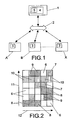
- the process used in this example applies to a system that has various user kits (A, B, ...X) and one head-end kit (1) .
- kits (A, B, ...X) and (1) are in two way communication over the electricity network (2) , establishing an upstream channel that goes from the user kits (A, B, ...X) to the head-end (1) as well as a downstream channel that goes from the head-end (1) kit to the user kits (A, B, ...X).
- Both the user kits (A, B, ...X) and the head-end (1) include a medium access controller (MAC) that is represented by the number 3 for the user kits and the number 4 for the head-end kit.
- MAC medium access controller
- the quantity of information that the user kits (A, B, ...X) may transmit is maximized and time latency is minimized for said kits (A, B, ...X).
- FDD Frequency Division Duplexing
- TDD Time Division Duplexing
- the transmission resources are distributed that is all the carriers in the OFDM system according to the transmission needs of each user at each moment, the quality of service parameters established for the user, the criteria to maximize the total capacity of the system and the criteria to minimize transmission latency, using for this the redistribution of the carriers of one symbol between the users (OFDMA), in time (TDMA), that is symbol to symbol, and by code (CDMA), optimising said redistribution by constant monitoring of the quality parameters for the electricity line, which vary over time.
- OFDMA redistribution of the carriers of one symbol between the users
- TDMA in time
- CDMA code
- the head-end kit (1) is responsible for the distribution of bandwidth between the user kits (A, B, ...X) taking into account factors such as the quality of service assigned to each one of the users.
- the upstream channel is divided into intervals of time and frequency, known as SLOTS, represented in Figure 2 , and these SLOTS are distributed between the users that wish to transmit.
- An arbiter or arbiter (5) located in the MAC (4) of the head-end (1) undertakes this distribution.
- SAM SLOT assignation messages
- connections, or channels are divided into a series of subchannels that are made up of groups of various carriers.
- Bandwidth in the subchannels is adjusted to the characteristics of the electricity network (2) , specifically that coherent bandwidth for the channel; said coherent bandwidth being defined for a multi carrier transmission systems like the difference in frequencies between the frequency position of the first and last carrier where the variation in frequency response in these carriers is less than a certain threshold (such as, for example 12 dB).
- Each user may be assigned optimum spectral zones so as to maximize the average bandwidth observed in each connection.
- subchannels may also be assigned to various users that observe an orthogonal frequency response one to the other (in subchannels where the user observes and low S/N, another user may observe a high S/N or vice -a- versa), so that would be possible to maximize bandwidth use.
- the objective is to have such a high granulation that a sub channel consists of only one carrier.
- complex algorithms are required that are far too costly in time and in the capacity of the process to assign users to the subchannels according to the frequency response in each sub channel, to maximize the advantage in average bandwidth.
- the connection is divided into eight or sixteen subchannels in the upstream and downstream connections, always in agreement with the limit imposed by the coherent bandwidth for the channel.
- Figure 3 shows an example of a table that four users A, B, C and D maintain with a frequency response greater than a determined threshold for each one of the four subchannels 13 , 14 , 15 and 16 that the upstream channel is divided into.
- This table is maintained in the head-end kit (1) and is used during the distribution of bandwidth to the users, so as to maximize average bandwidth when assigning subchannels to the users that observe an orthogonal frequency response.
- the table in Figure 3 shows an example of the first criterion of distribution used.
- the table mentioned or one similar is used to observe in which sub channel information may be sent.
- One of the most important points to optimising simultaneous communication by multiple users over the electricity network (2) is the dynamic assignation of bandwidth between the users.
- the objective is always to find the optimum assignation of carriers for each user, according to the criterion of maximizing the average capacity of the communications channel, which can be achieved by maximizing the signal-to-noise ratio in the total bandwidth.
- the head-end 1 knows this information for the upstream connection thanks to the resource petition messages (MPR) and the questioning of users (POLLING), while in the downstream it will know the destination of the packets to be sent.
- MPR resource petition messages
- POLLING questioning of users
- Figure 4 shows a graphic representation of the assignation of carriers for a downstream channel and the sending of information from the head-end kit 1 to some users A and B.
- the axis 18 and 19 represent respectively the signal-to-noise ratio, or bits per carrier and carrier frequency.
- the graphic 20 represents the channel observed in the direction of user A, that is, the channel response in the carriers in the downstream connection in terms of S/N or bits per carrier supported by user A that the head-end uses to optimise the transmission for this user while the graphic 21 represents the channel observe in the direction of user B.
- the distribution selected 17 by the head-end kit 1 is represented by the graphic 22 .
- the head-end kit 1 When the head-end kit 1 wants to transmit to a specific user it uses one of the subchannels and advises of the destination and uses the sub channel by means of the packet header sent by this sub channel. The users decode the header that indicates that a packet is directly to them and decode the corresponding data
- the head-end 1 can transmit in the downstream to one or various users (A, B, ...X).
- the head-end 1 may reorder the packets that must be sent to the various users to guarantee a determined QoS, even though it can also function in burst mode, that is, directly queuing the packets to be sent once the upper layers have determined what must be transmitted.
- connection packets are sent using one or various subchannels into which this connection is divided.
- each sub channel the fact that a packet is to be sent to a user is indicated by means of the headers already mentioned.
- the carriers in this sub channel can be used to speed up the transmission of information of a packet that has already been sent by another sub channel (aggregating the carriers of this sub channel to the sub channel that sent the initial packet with thereby accelerating the transmission of this packet).
- an information packet is sent by the aggregate sub channel with a header directed to the affected users.
- secure modulations such as BPSK or QPSK
- a user When a user decodes a header indicating that a packet is directed to it, it will know the corresponding sub channel or subchannels used to send the packet and it will take the data sent by these subchannels. If the header is not directed to it, it simply ignores the data associated with the header. If the header indicates that a new sub channel is being used to speed up the sending of a packet, it will decode the information that arrives via the new carriers as well as by the carriers in the original sub channel to obtain the information in the channel. By this means dynamic assignment of bandwidth is achieved in the downstream connection.
- headers are of great importance in the system as it allows a packet to be self-contained.
- the header contains all the information necessary about a packet such as destination, size, type of packet, if it has diversity in frequency or time, if it is in multicast mode (this mode indicates that it will be received by multiple users), etc.
- the upstream channel it is necessary to use an extra mechanism to know when to be able to send the packets, that is the distribution of SLOTS by the arbiter 5 and the SLOT assignation messages to communicate the distribution to the users.
- Figure 5 shows an example where four subchannels are used 24 in the downstream connection. From this Figure 5 it can be appreciated that the first and second subchannels, counting from the top, send packets that are preceded by a header 27 . In the fourth sub channel the transmission of a packet begins and previously, the third sub channel is used to accelerate the transmission of the same packet using the new carriers for this, as represented by the arrow 28 . This is indicated by means of the header 27 of the third sub channel.
- the arrow 23 represents the direction of the transmission of packets from the head-end kit 1 to the user A, B, C or D.
- the axis 25 and 26 represent time and frequency respectively.
- the channel For transmission in the upstream connection or channel, the channel is logically divided into time and frequency intervals known as SLOTS (as mentioned previously) to allow multiple users transmit simultaneously over the electricity network 2 in the direction of the head-end 1 .
- bandwidth can be dynamically assigned so that more or less time SLOTS (symbols) or frequency SLOTS (carriers) may be granted, so that the users can transmit information with different quality requirements (both bandwidth and latency) and optimising the transmission by granting SLOTS to the users that observe sufficient signal-to-noise ratio on the sub channel so as to use the most dense modulations.
- SLOTS When one of these SLOTS is assigned to a user kit (A, B, ...X), the user will know during what moments or time and in which carriers (and therefore in which frequency) it can send the information that it wants to transmit.
- the group of carriers associated with a SLOT is known as a sub channel in the upstream connection.
- the frequencies in each sub channel are adjusted to the coherent bandwidth of the channel so that each user observes a similar frequency response (arranged between certain limits) in each sub channel. This allows the capacity of the upstream channel to be increased.
- Figure 2 shows an example of SLOT distribution in a determined moment for a possible implementation.
- the axis 11 and 12 represent frequency and time respectively, while the SLOTS 7, 8, 9, and 10 represent SLOTS associated with different users A, B, C and D respectively, while the SLOTS 6 represent SLOTS that are free.
- the SLOTS referred to can be put to various uses by the user kits (A, B, ...X) such as:
- the head-end 1 indicates the purpose of each SLOT and which user or users can make use of it.
- the multiple access system is a central system, where the user kits (A, B, ...X) only transmit over the electricity network 2 when the head-end 1 previously decides and communicates the decision to the users implicated along with the quantity of information that can be transmitted, the type of modulation, etc.
- an automatic gain control and/or a power mask is used so that the signals of the user kits (A, B, ...X) arrive at the head-end kit 1 with approximately the same power, so that it is possible to work with A/D converters of very few bits without losing the signal-to-noise ratio in reception.
- the time window control is used to ensure that the signals from the various user kits (A, B, ...X) arrive at the head-end kit 1 at the same time, that is that the start of all the OFDM symbols sent arrive in the same time window at the head-end 1 , making the control by:
- each user kit obtains the sample frequency used by the head-end 1 , which it then uses to correct the transmission in the upstream channel so that frequency error in reception in the head-end 1 is null; the following methods are used to correct transmission frequency in the users kits (A, B, ...X):
- a frequency hopping method is used that if applied to the carriers in which the user kits (A, B, ...X) in the moment of transmission only use some of the carrier according to a sequence that indicates at each instant the carriers that may be used to send information, this sequence being predefined and being capable of being generated by a pseudorandom sequence whose seed is communicated by means of SAM messages, while if the said method is applied to the subchannels, the sequence is used to indicate to the user kit (A, B, ...X) which sub channel must be used to transmit at each moment in time.
- frequency hopping One of the advantages of "frequency hopping" is that the subchannels or the carriers are distributed to the users over time, that is, a user does not use a sub channel with high signal-to-noise ratio all the time, rather, it also uses (when the sequence indicates it) channels with low signal-to-noise ratio, so that on average all the users see an average channel and thereby maximise the transmission bandwidth for the electricity network.
- Figure 6 represents an example of frequency hoping for a communication between some user kits A, B, C, and D in the direction of a head-end 1 ; where the arrow 29 represents the direction of the transmission of data, while the arrow 30 represents the bandwidth of each sub channel.
- the axis 31 and 32 represent frequency and time respectively.
- the references 33 , 34 , 35 and 36 represent dispatches from the users A, B, C and D respectively, while the reference 37 represents a collision between users.
- the SLOT assignation messages SAM are messages that are periodically transmitted by the downstream channel and are decoded by all the users. Their periodicity depends on the size of the SLOTS that the upstream channel is divided into. Once the size of the frequency and time intervals (SLOTS) is selected, the periodicity must be constantly maintained.
- SAM SAM ⁇ ⁇ ⁇ ⁇ ⁇ ⁇ ⁇ ⁇ ⁇ ⁇ ⁇ ⁇ ⁇ ⁇ ⁇ ⁇ ⁇ ⁇ ⁇ ⁇ ⁇ ⁇ ⁇ ⁇ ⁇ ⁇ ⁇ ⁇ ⁇ ⁇ ⁇ ⁇ ⁇ ⁇ ⁇ ⁇ ⁇ ⁇ ⁇ ⁇ ⁇ ⁇ ⁇ ⁇ ⁇ ⁇ ⁇ ⁇ ⁇ ⁇ ⁇ ⁇ ⁇ ⁇ ⁇ ⁇ ⁇ ⁇ ⁇ ⁇ ⁇ ⁇ ⁇ ⁇ ⁇ ⁇ ⁇ ⁇ ⁇ ⁇ ⁇ ⁇ ⁇ ⁇ ⁇ ⁇ ⁇ ⁇ ⁇ ⁇ ⁇ ⁇ ⁇ ⁇ ⁇ ⁇ ⁇ ⁇ ⁇ ⁇ ⁇ ⁇ ⁇ ⁇ ⁇ ⁇ ⁇ ⁇ ⁇ ⁇ ⁇ ⁇ ⁇ ⁇ ⁇ ⁇ ⁇ ⁇ ⁇ ⁇ ⁇ ⁇ ⁇ ⁇ ⁇ ⁇ ⁇ ⁇ ⁇ ⁇ ⁇ ⁇ ⁇ ⁇ ⁇
- the SAM messages are essential to construct a system with dynamic assignation of bandwidth.
- the users need to transmit information, they make a request to the head-end 1 (using the methods of resource request or interrogation).
- the head-end 1 does not grant a fixed bandwidth to the user, rather it makes a dynamic distribution of bandwidth, offering more or less SLOTS to the users that make the request according to factors such as quantity of information to be sent, the quality of service requested, the type of information to be sent, the signal-to-noise ratio observed by the users in the SLOTS granted, etc.
- Sharing by means of OFDMA is undertaken so that the dynamic allocation of bandwidth is the most efficient possible.
- various users may transmit information using different carriers within the one OFDM symbol.
- the SLOT assignation messages may carry information on one or more SLOTS. Due to the importance of these SAM messages, they also carry preferably, some system to protect against errors such as codes with a large capacity to correct/detect errors, diversity in frequency and /or time, etc. Obviously, the messages to assign SLOTS always temporarily precede the SLOTS in the upstream channel to which they refer.
- the SAM messages may indicate if the SLOT assigned to a user is the first, the last or one of the intermediates. If the SLOT is the first of those granted to a user to send information, data will not be sent in all the symbols of the SLOT but rather various symbols of the SLOT must be used to send supplementary information, such as synchronization or equalization. If the SLOT is an intermediary it may be used in its entirety to send data. If it is the last SLOT assigned to a user kit (A, B, ...X) it sends information and a message to petition resources (MPR) so that the head-end kit 1 knows if it wants to send more information or not. This is not the only time that a kit may send resource petition messages, these may also be sent when the user has information to send and from the head-end kit 1 the purpose of the next SLOT is indicated to be the petition of resources.
- MPR message to petition resources
- the SAM messages that are sent by the downstream channel in the direction of each user include, at least, the following information:
- SAM messages may include:
- the MPR messages that have been referred to on various occasions previously are relatively short control messages that provide information on whether a user kit (A, B, ...X) wants to transmit data and optionally, on the size of the information block to be sent and the quality of service desired by a user kit (A, B, ...X), and they are sent at different moments. Said moments are:
- the user kit (A, B, ...X) sends an MPR message in the corresponding SLOT, where apart from the necessity to transmit is indicated, preferably, the quantity of information to be sent, the priority, the QoS required, the form in which this information may be decoded by the head-end and if it may be used to optimise the algorithm for SLOT assignation of the arbiter 5 ; if having previously foreseen that the head-end 1 detects a collision, a collision resolution algorithm is undertaken the user kits (A, B, ...X) transmit their petitions in the next MPR SLOT or POLLING, because the arbiter 5 will not grant them any transmission SLOT in the following SAMs.
- a user kit (A, B, ...X) wants to transmit, it follows the decisions taken by the head-end kit 1 regarding the moment for transmission, the carriers to use, the type of modulation and other parameters by means of the following process:
Landscapes
- Engineering & Computer Science (AREA)
- Signal Processing (AREA)
- Computer Networks & Wireless Communication (AREA)
- Quality & Reliability (AREA)
- Power Engineering (AREA)
- Cable Transmission Systems, Equalization Of Radio And Reduction Of Echo (AREA)
- Time-Division Multiplex Systems (AREA)
- Mobile Radio Communication Systems (AREA)
- Small-Scale Networks (AREA)
- Two-Way Televisions, Distribution Of Moving Picture Or The Like (AREA)
- Radio Relay Systems (AREA)
- Data Exchanges In Wide-Area Networks (AREA)
Claims (24)
- Verfahren für einen Mehrfachzugriff und eine Mehrfachübertragung von Daten von einem Punkt zu einem Mehrfachpunkt über das Stromnetz, enthaltend unterschiedliche Banutzereinrichtungen (A, B, ...X) und ein Head-End (1), in einer Zweiwegekommunikation mit Hilfe des Stromnetzes (2), wobei der Upstream-Kanal jener ist, der vom Head-End (1) zu den Benutzereinrichtungen (A, B, ...X) verläuft und jede der Benutzereinrichtungen (A, B, ...X) eine MAC (Medienzugriffssteuereinheit) (3,4) enthält, um die Menge der Informationen zu maximieren, die die Benutzereinrichtungen (A, B, ...X) übertragen können, um die Zeitlatenz in diesen Benutzereinrichtungen (A, B, ...X) zu minimieren; und wobei das Stromnetz für die Upstream-und die Downstream-Kanäle durch FrequenzteilDuplexieren (FDD) und/oder Zeitteil-Duplexieren (TDD) unterteilt wird, dadurch gekennzeichnet, dass es unterstützt:- den Zugriff durch unterschiedliche Benutzereinrichtungen (A, B, ...X) im Upstream-Kanal und das gleichzeitige Senden unterschiedlicher Informationsverknüpfungen durch das Head-End (1) im Downstream-Kanal mit Hilfe des Multiplexierens von OFDMA/TDMA/CDMA, des Multiplexierens durch orthogonale Frequenzteilung, des Multiplexierens durch Zeitteilung und/oder des Multiplexierens durch Codeteilung;- Kriterien, um jedem durch orthogonale Frequenzteilung multiplexierenden Träger im OFDM-System zum Benutzer und zwischen den Benutzern Informationen zuzuweisen, die in diesem Augenblick mit größerer Übertragungskapazität in diesem Träger, mit mehr Bits pro Träger oder einem besseren Signalrauschabstand gesendet werden sollen, um so die Übertragungskapazität sowohl im Upstream- als auch im Downstream-Kanal zu maximieren, d.h. um so das Frequenzansprechverhalten auszugleichen oder zu glätten, das vom Head-End sowohl bei der Ausgabe als auch beim Empfang wahrgenommen wird;- die Einstellung der Dienstgüte QoS in Abhängigkeit des Informationstyps und der Benutzer, die die Übertragung verlangen, wobei diese Dienstgüte gemäß dem Frequenzansprechverhalten zu bestimmten Augenblicken und den unterschiedlichen Distanzen zwischen den Benutzereinrichtungen (A, B, ...X) und dem Head-End (1) anpassbar ist;- die dynamische Zuweisung verfügbarer Bandbreite zwischen den unterschiedlichen Kommunikationsanfragen durch fortwährendes Berechnen und Überwachen des Signalrauschabstandes, der von den Benutzereinrichtungen (A, B, ...X) und dem Head-End (1) wahrgenommen wird, über die gesamte Bandbreite des Systems; so dass Übertragungsressourcen, d.h. die kombinierte Zahl von Trägern im System-OFDM, gemäß den Übertragungserfordernissen in jedem Augenblick rechtzeitig für jeden Benutzer, den Dienstgüte- QoS-Parametern, die für diesen Benutzer eingerichtet sind, den Kriterien zur Maximierung der Gesamtkapazität des Systems und den Kriterien zur Minimierung der Übertragungslatenz verteilt werden, wobei dafür die Neuverteilung der Träger eines Symbols zwischen den Benutzern, OFDMA, zeitlich, TDMA, d.h. Symbol zu Symbol, und durch Code, CDMA, verwendet wird, wobei die Neuverteilung durch fortwährendes Überwachen der Qualitätsparameter für die Stromleitung optimiert wird.
- Verfahren für einen Mehrfachzugriff und eine Mehrfachübertragung von Daten von einem Punkt zu einem Mehrfachpunkt über das Stromnetz nach Anspruch 1, dadurch gekennzeichnet, dass es die Maximierungseinrichtung enthält, d.h. Einrichtungen, die das Frequenzansprechverhalten, das vom Head-End (1) sowohl bei der Ausgabe als auch beim Empfang wahrgenommen wird, ausgleichen oder glätten, wobei die erwähnte Maximierung besteht aus:- Festlegen eines Vektorraums gleicher Größe für die Anzahl der Träger im OFDM-Kanal, wobei die Elemente, die diesen Raum bilden, die Zahl von Bits je Träger, die jeder Benutzer in jedem der Träger wahrnehmen kann, oder die Dimension der Konstellation ist, die in jedem Träger verwendet wird; vi=[vi1, vi2...vin], wobei N die Gesamtzahl von Trägem ist, die bei der Kommunikationsverbindung verwendet werden, die sich auf den Vektor bezieht, und vix die Zahl von verwendbaren Bits je Träger in den Kommunikationen von oder zum Benutzer h abhängig davon, auf welche Verbindung sich bezogen wird, im Träger x vom Blickpunkt des Head-Ends repräsentiert;- Verteilen der Träger zwischen den Benutzern mit zu sendenden Informationen, um so den Betrag für diesen Vektor zu maximieren: |v|, wobei v der Vektor von Bits je Träger oder die Dimension der Konstellation oder jedes Trägers, den jedes Head-End im laufenden Symbol verwendet, sowohl beim Upstream als auch beim Downstream ist;- Gruppieren der Gesamtzahl von Trägern N des Upstreams und des Downstreams in Teilkanälen der M Träger, um die Berechnung des Algorithmus' und die Implementierung zu vereinfachen, um so die Dimension des Vektorraums zu verringern, Erzeugen eines Vektorraums mit den Dimensionen N/M, wobei die Werte der Koordinaten die Summe sämtlicher Träger im Teilkanal sind, und ausgeben der Kapazität der Übertragung je OFDM-Symbol, das jeder Benutzer in jedem Teilkanal wahrnimmt, als Ergebnis;- Einstellen der Breite der Teilkanäle auf die kohärente Bandbreite, definiert als die Differenz der Frequenzen zwischen der Frequenzposition des ersten und des letzten Trägers, wobei die Änderung des Frequenzansprechverhaltens in diesen Trägern geringer ist als ein bestimmter Schwellenwert.
- Verfahren für einen Mehrfachzugriff und eine Mehrfachübertragung von Daten von einem Punkt zu einem Mehrfachpunkt über das Stromnetz nach Anspruch 1 und 2, dadurch gekennzeichnet, dass die MAC (4) im Head-End (1) einen Arbitrationsblock (5) oder Arbiter enthält, der für die dynamische Verteilung der Bandbreite in den Upstream- und Downstream-Kanälen für die unterschiedlichen Kommunikationen von den Benutzereinrichtungen (A, B,...X) verantwortlich ist, wobei die Kriterien, die von diesem Arbitrationsblock verwendet werden, um die Übertragungsbandbreite dynamisch zuzuweisen, jene sind, die zuvor beschrieben wurden, und für die die folgenden Einrichtungen verwendet werden:- paketorientierte Übertragung, der ein Header vorausgeht, der kennzeichnet, auf welchen Benutzer sich die Übertragung bezieht und zu welchen Bedingungen diese erfolgt;- Upstream- und Downstream-Kanäle werden derart in Teilkanäle unterteilt, dass Benutzer multiplexiert werden, um die Bandbreitensendung sowohl für die Upstream- als auch die Downstream-Kanäle zu maximieren, wobei die Kriterien der orthogonalen Übertragungskapazität in einer Funktion der Frequenz und der unterschiedlichen Benutzer verwendet werden;- eine sich über die Zeit ändernde dynamische Zuweisung von Trägern zu den unterschiedlichen Benutzern, so dass:- in der Downstream-Verbindung die Header jedes Paketes, das durch den Teilkanal gesendet wird, unter anderem die Bestimmung, die Größe und die verwendete Konstellation kennzeichnen, so dass die Benutzer in der Lage sein müssen, sämtliche Header, die durch einen beliebigen Kanal empfangen werden, zu erfassen und zu verstehen, während lediglich die Informationen vom Paket, das sich auf sie bezog, demoduliert werden, wenn ihnen der Bitvektor je Träger bekannt ist, der bei der Modulation verwendet wird;- in der Upstream-Verbindung, abgesehen von der Teilung in Teilkanäle, die auf die kohärente Bandbreite eingestellt sind, die Zeitteilung derart erfolgt, dass ein SCHLITZ als Anzahl der Symbole im Upstream-Kanal zwischen zwei Zuordnungsnachrichten dieser SCHLITZE, SAM, definiert wird, wobei diese die Einheiten bilden, die vom Arbiter (5) verwendet werden, um Benutzern Ressourcen zuzuweisen, wobei diese Ressourcen periodisch zugewiesen werden, indem Zuordnungsnachrichten, bekannt als SAM, durch die Downstream-Verbindung zu einer Benutzereinrichtung (A, B, ...X) gesendet werden, und die Informationen über einen oder mehrere SCHLITZE enthalten können und die periodisch eine bestimmte Anzahl von Abtastungen vor den SCHLITZEN gesendet werden, auf die sich beziehen, d.h. sie gehen diesen zeitlich voraus, so dass, wenn die Anzahl von Symbolen eines SCHLITZES klein ist, der erzielbare Latenzboden ebenfalls klein ist, die Komplexität des Systems jedoch größer ist, wie es auch der Aufwand der Übertragungskapazität im Upstream-Kanal bei den Ressourcen-Zuordnungsnachrichten SAM ist;- kontinuierliches Messen des Signalrauschabstandes für jeden Benutzer in sämtlichen Upstream- und Downstream-Kanälen, um kontinuierlich die Kapazität der Übertragung für sämtliche Benutzer in jedem der Teilkanäle zu aktualisieren;- kontinuierliche Informationen, die aussagen, welche Benutzer (A, B, ...X) eine Übertragung in welchem Umfang vornehmen wollen, mit Hilfe einer Abfrage, d.h. durch POLLEN, SCHLITZE bzw. Ressourcen-Gesuchsnachrichten MPR, wobei die oberen Schichten des Head-Ends (1) im Upstream jene sind, die den Arbiter (5) über die Quantität der Informationen, die zur Übertragung bereitstehen, und über die Benutzer informieren, von denen diese stammen; und- Informationen über die QoS, die Bandbreite und die Latenz, die für jeden Benutzer in der Funktion der Kanalkapazität und der Zahl von Benutzern definiert sind, die am Head-End (1) hängen, so dass die Zahl von SCHLITZEN, die fortwährend einem Benutzer zugewiesen werden, in den Fällen begrenzt werden kann, in denen unterschiedliche Benutzer zu einem bestimmten Moment senden wollen, wodurch die Gleichberechtigung eines Zugriffs in der Upstream-Verbindung beibehalten wird.
- Verfahren für einen Mehrfachzugriff und eine Mehrfachübertragung von Daten von einem Punkt zu einem Mehrfachpunkt über das Stromnetz nach Anspruch 3, dadurch gekennzeichnet, dass, wenn das Head-End (1) zu einer oder mehreren Benutzereinrichtungen (A, B, ...X) über den Downstream-Kanal senden will, der Arbiterblock (5) dynamisch die Bandbreite verteilt, wobei er einen oder mehrere der erwähnten Teilkanäle verwendet, und er den Bestimmungsort über die Verwendung dieses Teilkanals oder dieser Teilkanäle mit Hilfe der Header in den Informationspaketen unterweist, die durch die Teilkanäle gesendet werden, so dass jede Benutzereinrichtung die entsprechenden Daten decodiert, wenn sie erfasst, dass sich einer der Header auf ein Paket bezieht, das ihr zugesandt wurde, damit eine Benutzereinrichtung (A, B, ... X) mehr als ein Paket von unterschiedlichen eindeutigen Teilkanälen empfangen kann, wodurch es möglich ist, diesem Header die Übertragung eines neuen Paketes zum Benutzer zu kennzeichnen, oder dass der Teilkanal, auf dem der Header gesendet wird, verwendet wird, um die Übertragung eines Paketes zu beschleunigen, das zuvor durch einen anderen Teilkanal oder andere Teilkanäle zum selben Benutzer gesendet wurde, indem die Träger dieses neuen Teilkanals und jene, die bereits für die Sendung des vorherigen Paketes verwendet wurden, vereinigt werden.
- Verfahren für einen Mehrfachzugriff und eine Mehrfachübertragung von Daten von einem Punkt zu einem Mehrfachpunkt über das Stromnetz nach Anspruch 4, dadurch gekennzeichnet, dass Header, die durch die Teilkanäle in der Downstream-Verbindung gesendet werden, vorzugsweise mit Modulationen moduliert werden, die einen geringen Signalrauschabstand für ihre Decodierung aufweisen, wie etwa vorzugsweise Differentialphasenmodulation, DPSK, und/oder Quadraturphasenmodulation, QPSK, zusammen mit Fehlerkorrektur-/Erfassungs-Codes und einer Frequenzdiversität, mit der dieselben Informationen auf unterschiedlichen Trägern gesendet werden, und/oder Zeitdiversität, mit der dieselben Informationen zu unterschiedlichen Augenblicken gesendet werden, um die Wahrscheinlichkeit der korrekten Decodierung des Headers zu erhöhen.
- Verfahren für einen Mehrfachzugriff und eine Mehrfachübertragung von Daten von einem Punkt zu einem Mehrfachpunkt über das Stromnetz nach Anspruch 4, dadurch gekennzeichnet, dass die Header, auf die sich bereits bezogen wurde, sämtliche Informationen beinhalten, die für das geeignete Informationspaket erforderlich sind, so dass der Bestimmungsort, die Pakettypen, die Anwendung der Diversifikation der Frequenz und/oder der Zeit, ob das Paket für einen Benutzer oder unterschiedliche Benutzer, d.h. MEHRFACHSENDE-Betriebsart, und/oder sämtliche Benutzer, d.h. RUNDSENDE-Betriebsart, bestimmt ist, die Modulation, die für jeden Träger verwendet wurde, sofern die FEC-Redundanz, d.h. der Fehlerkorrektur-/Erfassungs-Code, verwendet wurde, um das Informationspaket zu schützen, und/oder ob der Teilkanal, zu dem der Header gesendet wird, verwendet werden, um die Übertragung von Informationen von einem Paket, das zuvor durch einen anderen Teilkanal gesendet wurde, oder anderen Informationen zu beschleunigen.
- Verfahren für einen Mehrfachzugriff und eine Mehrfachübertragung von Daten von einem Punkt zu einem Mehrfachpunkt über das Stromnetz nach Anspruch 3, dadurch gekennzeichnet, dass die SCHLITZE, in die die Upstream-Verbindung geteilt wird, von den Benutzereinrichtungen (A, B, ...X) für folgende Zwecke verwendet werden kann:- die Übertragung von Anfragen auf Abfragenachrichten, POLLEN,- die Übertragung von Ressourcen-Gesuchsnachrichten, MPR,- die Übertragung von Daten, die sämtliche oder einen der folgenden Gegenstände beinhalten:- Synchronisationssequenzen,- Ausgleichssequenzen- Sequenzen, um den Signalrauschabstand zu schätzen, und/oder- Daten über Informationen, die der Benutzer (A, B, ...X) zum Head-End (1) senden möchte.
- Verfahren für einen Mehrfachzugriff und eine Mehrtachübertragung von Daten von einem Punkt zu einem Mehrfachpunkt über das Stromnetz nach Anspruch 3, dadurch gekennzeichnet, dass in der Upstream-Verbindung der Arbiter (5) des Head-Ends (1) die Einrichtung enthält, um jede Benutzereinrichtung (A, B, ...X) mit der am besten geeigneten Bandbreite in variabler Form zu versorgen, wodurch mehr oder weniger SCHLITZE gemäß den Parametern, wie etwa der Menge der zu sendenden Informationen, der Qualität des angefragten Dienstes, dem Typ der zu sendenden Informationen, dem Signalrauschabstand, der von den Benutzern in den gewährten SCHLITZEN wahrgenommen wird, mit Hilfe eines optimalen Zuweisungsalgorithmus von SCHLITZEN angeboten und die Entscheidungen, die von diesem Arbiter (5) getroffen werden, den Benutzereinrichtungen (A, B, ...X) mit Hilfe von SAM-Nachrichten zugestellt werden.
- Verfahren für einen Mehrfachzugriff und eine Mehrfachübertragung von Daten von einem Punkt zu einem Mehrfachpunkt über das Stromnetz gemäß der Ansprüche 3 bis 7, dadurch gekennzeichnet, dass das Verfahren, das angewendet wird, um Entscheidungen über die Verteilung von SCHLITZEN in der Upstream-Verbindung, wie sie vom Arbiter (5) des Head-Endes (1) getroffen werden, das Senden der Zuweisungsnachrichten SAM durch die Downstream-Verbindung zu jeder Benutzereinrichtung (A, B, ...X) ist und Informationen über einen oder unterschiedliche SCHLITZE enthält, die periodisch und immer mit einer bestimmten Anzahl von Abtastungen vor den SCHLITZEN, auf die sie sich beziehen, d.h. sie gehen diesen zeitlich voraus, gesendet werden, wobei diese wenigstens beinhalten:- die Kennzeichnung des Benutzers oder der Benutzer (A, B, ... X), für die der SCHLITZ vergeben ist,- die Kennzeichnung der Verwendung, der jeder SCHLITZ zugeführt werden soll,- die Zahl der Symbole innerhalb des SCHLITZES, der an jeden Benutzer vergeben wird,- die Zahl des Symbols, das dort beginnt, wo jeder Benutzer den SCHLITZ benutzen kann,- Informationen über die Modulation, die für die Übertragung von Daten verwendet werden muss, vorzugsweise QPSK oder eine Konstellation, die mit dem Head-End (1) für eine bestimmte Fehleraufgabe in Funktion des Signalrauschabstandes im Kanal ausgehandelt wird,sie können zudem enthalten:- die Bestätigung des Empfangs der Ressourcen-Gesuchsnachrichten (MPR),- die Beschränkung des Zugriffs auf bestimmte Benutzereinrichtungen (A, B, ...X),- die Korrektur von Umwegen im zeitlichen Übertragungsfenster der Benutzereinrichtungen (A, B, ...X),- Informationen über die Leistungssteuerung,- den Typ und die Anzahl von Daten, die vom Benutzer gesendet werden sollen, d.h. ob 0 oder mehr Ausgleichs- oder Synchronisationssymbole gesendet werden sollen, und eine Schätzung des Tons/Rauschens und/oder der Daten in den Informationen, wobei diese SAM-Nachrichten vorzugsweise mit einem bestimmten Zusatzschutz gegen Fehler geschützt sind, wie etwa durch Codes mit einer größeren Kapazität zur Korrektur/Erfassung von Fehlern, die Diversität der Frequenz oder der Zeit und andere Systeme.
- Verfahren für einen Mehrfachzugriff und eine Mehrfachübertragung von Daten von einem Punkt zu einem Mehrfachpunkt über das Stromnetz nach Anspruch 3, dadurch gekennzeichnet, dass im Downstream-Kanal der Arbiter (5) die Verteilungsfunktion ausführt, die Parameter, wie etwa die Signalrauschabstände oder das Frequenzansprechverhalten, die die Benutzereinrichtungen (A, B, ...X) in den Teilkanälen wahrnehmen, die Nachrichtenpriorität, die Menge der Informationen und dergleichen, berücksichtigt; während die Benutzer die Header, die über Downstream-Verbindung gesendet wurden, decodieren und entscheiden, ob sie die Daten nehmen müssen, die durch denselben Teilkanal gesendet wurden, wie der Header, beginnend bei den Informationen über den Bestimmungsort, die diesen Header enthalten.
- Verfahren für einen Mehrfachzugriff und eine Mehrfachübertragung von Daten von einem Punkt zu einem Mehrfachpunkt über das Stromnetz nach Anspruch 10, dadurch gekennzeichnet, dass der Arbiter (5) die Verwendung eines oder mehrerer Teilkanäle für entsprechende Absendung oder die Erhöhung der Bandbreite eines Benutzers anfordern kann, wobei das Ziel darin besteht, die Übertragung des Paktes zu beschleunigen, auf das sich bezogen wurde, wobei mehr als ein Teilkanal zugewiesen wird, um mehr als ein Paket von Informationen gleichzeitig zu übertragen und eine dieser Entscheidungen mit Hilfe des Headers in den abgesendeten Nachrichten gekennzeichnet wird.
- Verfahren für einen Mehrfachzugriff und eine Mehrfachübertragung von Daten von einem Punkt zu einem Mehrfachpunkt über das Stromnetz nach Anspruch 10 und 11, dadurch gekennzeichnet, dass der Arbiter (5) die Benutzer (A, B, ...X) auf die unterschiedlichen Teilkanäle sowohl im Upstream als auch im Downstream verteilen kann, so dass die benutzte Bandbreite in jedem Augenblick maximiert wird, basierend auf dem Frequenzansprechverhalten, das jeder Benutzer (A, B, ...X) in den unterschiedlichen Teilkanälen wahrnehmen kann.
- Verfahren für einen Mehrfachzugriff und eine Mehrfachübertragung von Daten von einem Punkt zu einem Mehrfachpunkt über das Stromnetz nach Anspruch 9 und 12, dadurch gekennzeichnet, dass der Arbiter (5) für die Upstream- und die Downstream-Kanäle QoS als ein Kriterium zum Zeitpunkt der Zuweisung von Ressourcen zur Minimierung der Latenz verwendet, d.h. jede Benutzereinrichtung (A, B,... X) überträgt so schnell wie möglich, nachdem eine Zugriffsanfrage in der Upstream-Verbindung plaziert wurde, oder ein Paket wird vom Head-End (1) zu einem Benutzer (A, B, ...X) so schnell wie möglich gesendet.
- Verfahren für einen Mehrfachzugriff und eine Mehrfachübertragung von Daten von einem Punkt zu einem Mehrfachpunkt über das Stromnetz nach Anspruch 3, dadurch gekennzeichnet, dass die MPR-Nachricht vorzugsweise eine relativ kurze Steuernachricht ist, um zu melden, wenn eine Benutzereinrichtung (A, B, ...X) Daten senden will, und wahlweise über die Größe des zu sendenden Informationsblocks und die Dienstgüte, die von der Benutzereinrichtung (A, B, ...X) verlangt wird, während der folgenden Augenblicke Auskunft zu geben:- wenn eine SAM-Nachricht, die von der Benutzereinrichtung (A, B, ...X) empfangen wird, kennzeichnet, dass der nächste SCHLITZ, der dieser Einrichtung zugewiesen ist, der letzte in einer Abfolge von Datenübertragungs-SCHLITZEN ist, verwendet die Benutzereinrichtung (A, B, ...X) einen Teil des SCHLITZES, um eine MPR-Nachricht für den Fall zu senden, dass sie zusätzliche zu sendende Daten hat,- wenn die Benutzereinrichtung (A, B, ...X) keine zusätzlichen zu sendenden Daten hat und ihr trotzdem SCHLITZE zugewiesen sind, kennzeichnet in diesem Fall die entsprechende MPR-Nachricht dem Head-End (1), ihr keine weiteren SCHLITZE zuzuweisen und die verbleibenden SCHLITZE anderen Benutzereinrichtungen (A, B, ...X) neu zuzuweisen,- wenn eine Benutzereinrichtung (A, B, ...X) einem SCHLITZ durch eine SAM zugewiesen ist, die für das Gesuch von Ressourcen bestimmt ist (MPR), so dass die Benutzereinrichtung/en (A, B, ...X), die übertragen wollen, ihre MPR zu diesem SCHLITZ senden, wobei sie einen kleinen Teil davon zufallsartig verwenden oder einen Algorithmus benutzen, der den Typ des Benutzers, den Typ der Informationen und andere Parameter berücksichtigt, und so, dass das Head-End (1) mögliche Kollisionen erfasst, wenn unterschiedliche Benutzereinrichtungen beim Gesuch von Ressourcen in derselben Zone des SCHLITZES übereinstimmen, werden derartige Kollisionen mit Hilfe von Algorithmen, die nach dem Stand der Technik bekannt sind, aufgelöst, oder indem es den Benutzereinrichtungen (A, B, ...X) überlassen wird, ihre Positionen bei einer späteren Vermittlung erneut zu senden, bis die Konkurrenz zwischen den Benutzern (A, B, ...X) aufgelöst ist.
- Verfahren für einen Mehrfachzugriff und eine Mehrfachübertragung von Daten von einem Punkt zu einem Mehrfachpunkt über das Stromnetz nach Anspruch 3,
dadurch gekennzeichnet, dass es POLL-SCHLITZEN gestattet, eine maximale Zahl von Benutzern (A, B, ...X) darüber zu befragen, ob sie über zu sendende Informationen verfügen oder nicht, indem ein Abfragealgorithmus verwendet wird, wobei der Zweck darin besteht, dass dieselben Benutzereinrichtungen (A, B, ...X) nicht immer die abgefragten sind, wenn diese maximale Zahl überschritten wird, und im Head-End (1) an sich als Einrichtung enthalten sind, um die Benutzereinrichtungen in unterschiedliche Kategorien in Abhängigkeit der Aktivität zu klassifizieren, die die Benutzer aufweisen, und darin, diese Informationen zu beziehen, die das Head-End (1) Abfrage-SCHLITZEN zuweist (POLLEN), über deren Aktivität es Informationen verlangt, wobei diese in dem Teil des SCHLITZES antworten, der ihnen zugeordnet wird, wenn sie zu sendende Informationen haben. - Verfahren für einen Mehrfachzugriff und eine Mehrtachübertragung von Daten von einem Punkt zu einem Mehrfachpunkt über das Stromnetz nach Anspruch 7 und 9, dadurch gekennzeichnet, dass, wenn eine Benutzereinrichtung (A, B, ...X) zu sendende Daten hat, diese wartet, bis eine Nachricht, SAM, meldet, dass einer der folgenden SCHLITZE für das POLLEN oder MPR bestimmt wird, so dass, wenn sie eine POLLENDE SAM empfängt, die folgenden Schritte unternommen werden:- die Benutzereinrichtung (A, B, ...X) verifiziert bestimmte Bits in der SAM, die kennzeichnen, ob sie zur Gruppe von Benutzern gehört, die den nächsten POLL-SCHLITZ verwenden können,- die SAM-Nachricht kennzeichnet die Positionen, in denen die Benutzereinrichtung (A, B, ... X) auf die Ressourcen-Anfrage antworten muss, wobei diese Positionen durch das Head-End (1) bestimmt wird, das fortwährend den Signalrauschabstand überwacht und das von der Benutzereinrichtung (A, B, X) in den unterschiedlichen Trägern, d.h. den verfügbaren Frequenzen für die Upstream-Kommunikation erkannt werden kann;- der POLL-SCHLITZ wird in unterschiedliche gültige Zonen unterteilt, die kleine Abschnitte von Zeit/Frequenz sind, und die Benutzereinrichtungen (A, B, ...X) wählen die Zonen, die durch die SAM gekennzeichnet werden, um eine Kollision der Gesuche zu vermeiden;- die Benutzereinrichtung (A, B, ...X) sendet eine POLL-Nachricht in der gewählten Zone; und- wenn das POLLEN im Head-End (1) empfangen worden ist, empfängt die Benutzereinrichtung (A, B, ...X) später SAM-Nachrichten, die SCHLITZE zuweisen, wohingegen, wenn es diese nicht empfangen hat, die Benutzereinrichtung (A, B, ...X) warten muss, bis es eine neue POLL-SAM gibt, wohingegen, wenn sie eine Meldung eines MPR-SCHLITZES in einer SAM empfangen hat, die Benutzereinrichtung (A, B, ...X) die MPR-Nachricht in diesem SCHLITZ sendet, in dem sie, abgesehen von der Notwendigkeit einer Übertragung, vorzugsweise die Größe der Informationen, die sie senden möchte, die Priorität und die erforderliche QoS anzeigt, so dass diese Informationen durch den Header decodiert und verwendet werden können, um den Algorithmus für die Zuweisung von Arbitrage-SCHLITZEN (5) zu optimieren, wobei geplant wurde, dass, wenn das Head-End (1) eine Kollision erfasst, es einen Algorithmus beginnen wird, um diese Kollision aufzulösen, oder auf die Benutzereinrichtungen (A, B, ...X) wartet, dass sie ihr Gesuch in einem anderen MPR-SCHLITZ übertragen oder POLLEN, da der Arbiter (5) keinen Datenübertragungs-SCHLITZ in der folgenden SAM garantiert.
- Verfahren für einen Mehrfachzugriff und eine Mehrfachübertragung von Daten von einem Punkt zu einem Mehrfachpunkt über das Stromnetz, nach Anspruch 2, 10 und 16, dadurch gekennzeichnet, dass bei der Übertragung die Benutzereinrichtungen (A, B, ...X) den Entscheidungen, die vom Head-End (1) getroffen wurden und den Augenblick der Sendung, den zu verwendenden Träger, den Typ der Modulation und andere Parameter berücksichtigen, gemäß dem folgenden Ablauf folgen:- nach korrektem Empfang der Übertragungsanfragen von einer Benutzereinrichtung (A, B, ...X), weist das Head-End (1) ausreichende Zeit-/Frequenz-SCHLITZE zu, beginnend bei einer Schätzung, die gemäß der Aktivität, der Übertragungskapazität, der Dienstgüte und anderer Parameter der Benutzreinrichtung (A, B, ...X), die das Gesuch ausgab, und gemäß dem Signalrauschabstand vorgenommen wurde, der im Teilkanal beobachtet wurde, wobei der Arbiter (5) für die Verteilung der SCHLITZE zwischen den Benutzern verantwortlich ist, die das Gesuch ausgaben, um Daten mit dem zuvor erwähnten Algorithmus zu senden;- wenn eine Benutzereinrichtung (A, B, ...X) mit Hilfe der Demodulation und des Decodierens die SAM-Nachricht erfasst, die ein oder mehrere SCHLITZE für sie bestimmt haben, führt sie die folgenden Tätigkeiten aus:- Prüfen des Typs jedes einzelnen der zugewiesenen SCHLITZE und der Modulation, die in jedem Träger jedes SCHLITZES verwendet werden muss, wobei die SAM-Nachricht für die Kommunikation dieser Informationen gemäß dem verantwortlich ist, was durch den Arbiter (5) zugewiesen wurde;- Berechnen, wie viele Bits sie insgesamt übertragen kann und Extrahieren der Daten aus ihrem Speicher, wobei dies Informationen über Daten, das Ausgleichen, die Synchronisation, die Schätzung von Ton/Rauschen oder eine beliebige andere Kombination aus diesen sind, wie es in der SAM-Nachricht gekennzeichnet ist, die diesem SCHLITZ zugewiesen ist;- Warten auf das Startsymbol im SCHLITZ, der übertragen muss, und Ausführen der Übertragung der Daten mit der gewählten Modulation;- wenn beliebige der zugewiesenen SCHLITZE, vom Typ der Diversität der Zeit oder der Frequenz sind, muss die Benutzereinrichtung (A, B, ...X) die modulierten Informationen sicher, vorzugsweise in QPSK, wiederholt zu unterschiedlichen Zeitpunkten in der Frequenz senden, d.h. senden derselben Informationen vom Träger k in den Trägern k+N, k+2*N, etc. in Abhängigkeit von der verwendeten Diversität und der zugewiesenen Träger, oder wiederholt zu unterschiedlichen Zeitpunkten zu unterschiedlichen Augenblicken, d.h. Zeitdiversität;- wenn der SCHLITZ vom POLL- oder MPR-Typ ist, wird der Vorgang ausgeführt, der in Anspruch 16 festgelegt ist.
- Verfahren für einen Mehrfachzugriff und eine Mehrfachübertragung von Daten von einem Punkt zu einem Mehrfachpunkt über das Stromnetz nach Anspruch 1, dadurch gekennzeichnet, dass das CDMA-Multiplexieren, das bereits erwähnt wurde, ein Frequenzsprungsverfahren beinhaltet, bei dem, wenn es auf die Träger angewendet wird, die Benutzereinrichtungen (A, B, ...X) im Augenblick der Übertragung lediglich einige der Träger gemäß einer Sequenz verwenden, die in jedem Moment die Träger kennzeichnet, die zum Senden von Informationen verwendet werden können, wobei diese Sequenz vordefiniert und in der Lage ist, durch eine Pseudozufalls-Sequenz erzeugt zu werden, deren Keim mit Hilfe von SAM-Nachrichten kommuniziert wird, wohingegen, wenn das Verfahren auf die Teilkanäle angewendet wird, die Sequenz verwendet wird, um der Benutzereinrichtung (A, B, ... X) zu kennzeichnen, welcher Teilkanal verwendet werden muss, um zum jeweiligen Zeitpunkt zu übertragen.
- Verfahren für einen Mehrfachzugriff und eine Mehrfachübertragung von Daten von einem Punkt zu einem Mehrfachpunkt über das Stromnetz nach Anspruch 3, dadurch gekennzeichnet, dass die Informationspaket-Header, die durch die SCHLITZE in der Upstream-Verbindung gesendet werden, moduliert werden, vorzugsweise mit Modulationen, die für die Decodierung geringe Signalrauschabstands-Anforderungen haben, wie etwa DPSK, Differentialphasenmodulation und/oder QPSK, Quadraturphasenmodulation, zusammen mit Korrekturcodes/Fehlererfassung und Frequenzdiversität, die dieselben Informationen über bestimmte Träger sendet und/oder Zeitdiversität, die dieselben Informationen zu unterschiedlichen Augenblicken sendet, um die Wahrscheinlichkeit einer korrekten Decodierung zu erhöhen.
- Verfahren für einen Mehrfachzugriff und eine Mehrfachübertragung von Daten von einem Punkt zu einem Mehrfachpunkt über das Stromnetz gemäß Anspruch 3 und 19, dadurch gekennzeichnet, dass die Header sämtliche Informationen über das entsprechende Informationspaket beinhalten, wie etwa Informationen über den Pakettyp, die Verwendung der Frequenz- und/oder Zeitdiversität, die Modulation, die verwendet wird, um die Informationen im Paket zu modulieren, wie beispielsweise sämtliche Träger in QPSK oder sämtliche Träger mit der Konstellation, die für eine bestimmte Fehlerrate in Funktion des Signalrauschabstandes auf dem Kanal fixiert ist, nachdem jeder Benutzer mit dem Head-End verhandelt wurde, und die FEC-Redundanz, Codekorrekturredundanz/Fehlererfassung, mit denen die Informationen im Paket geschützt werden.
- Verfahren für einen Mehrfachzugriff und eine Mehrfachübertragung von Daten von einem Punkt zu einem Mehrfachpunkt über das Stromnetz nach Anspruch 3, dadurch gekennzeichnet, dass es eine Abfolge von Steuerungen enthält, um den Signalrauschabstand für sämtliche Benutzer zu maximieren, ohne einen von diesen während der Übertragung zu beeinträchtigen, wodurch ein Mehrfachzugriff im selben OFDM-Symbol und in der Upstream-Verbindung sowie die Übertragung von mehreren Informationspaketen gleichzeitig in der Downstream-Verbindung gestattet ist, wobei diese Steuerungen sind:- Steuerung der eingekoppelten Leistung für jede Benutzervorrichtung (A, B, ... X);- Steuerung des Zeitfensters für jede Benutzereinrichtung (A, B, ... X);- Steuerung der Abtastfrequenz, d.h. der Synchronisation der Frequenz der Benutzereinrichtungen (A, B, ...X).
- Verfahren für einen Mehrfachzugriff und eine Mehrfachübertragung von Daten von einem Punkt zu einem Mehrfachpunkt über das Stromnetz nach Anspruch 21, dadurch gekennzeichnet, dass eine automatische Verstärkungssteuerung und/oder eine Leistungsmaske an diesen Steuerungen der eingekoppelten Leistung verwendet werden, durch die die Signale von den Benutzereinrichtungen (A, B, ...X) am Head-End (1) mit etwa derselben Leistung eintreffen, so dass man mit A/D-Wandlern analog/digital mit wenigen Bits arbeiten kann, ohne den Signalrauschabstand beim Empfang zu verlieren.
- Verfahren für einen Mehrfachzugriff und eine Mehrfachübertragung von Daten von einem Punkt zu einem Mehrfachpunkt über das Stromnetz nach Anspruch 21, dadurch gekennzeichnet, dass die Fenstersteuerung verwendet wird, um die Signale von den unterschiedlichen Benutzern (A, B, ...X) zu steuern, die am Head-End (1) zur selben Zeit eintreffen, d.h. der Beginn sämtlicher gesendeter OFDM-Symbole trifft im selben Zeitfenster am Head-End (1) ein; diese Steuerung erfolgt durch:- eine Einstellung im offenen Regelkreis, die im Downstream-Kanal auftritt und eine grobe Einstellung im Zeitfenster repräsentiert und bei der jede Benutzereinrichtung (A, B, ...X) die Pakete erkennen kann, die über den Downstream-Kanal eintreffen, und von der die Abtastungen, die bei der Übertragung verzögert/vorgezogen werden sollen, näherungsweise abgeleitet werden, so dass sie am Head-End (1) zum optimalen Zeitpunkt eintreffen;- eine Einstellung im geschlossenen Regelkreis, die im Upstream-Kanal und im Downstream mit Hilfe der SAM-Nachrichten auftritt, die eine Feineinstellung im Zeitfenster repräsentieren und bei der das Head-End (1) die Anzahl von Abtastungen erfasst und übermittelt, die von der Benutzereinrichtung (A, B, ...X) verzögert/vorgezogen werden muss, um den optimalen Augenblick für die Übertragung zu erreichen.
- Verfahren für einen Mehrfachzugriff und eine Mehrfachübertragung von Daten von einem Punkt zu einem Mehrfachpunkt über das Stromnetz nach Anspruch 21, dadurch gekennzeichnet, dass bei der Frequenzsteuerung und der folgenden Synchronisation jeder Benutzereinrichtung (A, B, ...X) die Abtastfrequenz bekannt ist, die vom Head-End (1) verwendet wird, die sie anschließend verwendet, um die Übertragung im Upstream-Kanal zu korrigieren, so dass ein Frequenzfehler beim Empfang Null ist; die folgenden Verfahren werden angewendet, um die Übertragungsfrequenz in den Benutzereinrichtungen (A, B, ...X) zu korrigieren:- Restfehlerkorrektur in den Trägern mit Hilfe eines Rotors, der die Rotation kompensiert, unter der jeder Träger leidet, wobei jeder Träger mit der komplexen Exponentialgröße des gewünschten Winkels multipliziert wird; und- Abtastfrequenzkorrektur mit Hilfe eines Frequenzkorrekturelementes, das aus einer Neuabtasteinrichtung im digitalen Behandlungsteil des Systems und/oder dem variablen Oszillator oder VCXO im analogen Teil bestehen kann, wobei berücksichtigt wird, dass, wenn die entsprechenden Takte ausreichend präzise sind, es nicht erforderlich ist, das Frequenzkorrekturelement zu verwenden und es ausreichend ist, lediglich den Restfehler in den Trägern mit dem Rotor zu korrigieren.
Applications Claiming Priority (3)
| Application Number | Priority Date | Filing Date | Title |
|---|---|---|---|
| ES200100916A ES2186531B1 (es) | 2001-04-19 | 2001-04-19 | Procedimiento de acceso multiple y multiple transmision de datos para un sistema multiusuario de transmision digital de datos punto a multipunto sobre red electrica. |
| ES200100916 | 2001-04-19 | ||
| PCT/ES2002/000187 WO2002087104A2 (es) | 2001-04-19 | 2002-04-17 | Procedimiento de acceso y transmision multiples en un sistema punto a multipunto sobre red electrica |
Publications (2)
| Publication Number | Publication Date |
|---|---|
| EP1388954A2 EP1388954A2 (de) | 2004-02-11 |
| EP1388954B1 true EP1388954B1 (de) | 2008-03-19 |
Family
ID=8497492
Family Applications (1)
| Application Number | Title | Priority Date | Filing Date |
|---|---|---|---|
| EP02724317A Expired - Lifetime EP1388954B1 (de) | 2001-04-19 | 2002-04-17 | Verfahren für mehrfachzugriff und -übertragung in einem punkt-zu-mehrpunkt-system auf einem elektrischen netzwerk |
Country Status (16)
| Country | Link |
|---|---|
| US (1) | US7460553B2 (de) |
| EP (1) | EP1388954B1 (de) |
| JP (1) | JP4302988B2 (de) |
| KR (1) | KR100814354B1 (de) |
| CN (1) | CN1309180C (de) |
| AT (1) | ATE389978T1 (de) |
| AU (1) | AU2002255011B2 (de) |
| BR (1) | BR0209123A (de) |
| CA (1) | CA2444397A1 (de) |
| DE (1) | DE60225684T2 (de) |
| EA (1) | EA005473B1 (de) |
| ES (2) | ES2186531B1 (de) |
| IL (2) | IL158370A0 (de) |
| MX (1) | MXPA03009501A (de) |
| PT (1) | PT1388954E (de) |
| WO (1) | WO2002087104A2 (de) |
Families Citing this family (104)
| Publication number | Priority date | Publication date | Assignee | Title |
|---|---|---|---|---|
| ES2188372B1 (es) * | 2001-05-23 | 2004-11-16 | Diseño De Sistemas En Silicio, S.A. | Procedimiento para la sincronizacion de la comunicacion mediante modulacion ofdm de multiples equipos de usuario con un equipo de cabecera (canal ascendente). |
| CN1640045A (zh) * | 2001-12-05 | 2005-07-13 | 高通股份有限公司 | 调整通信系统服务质量的系统与方法 |
| US7573863B2 (en) * | 2002-08-22 | 2009-08-11 | Bae Systems Information And Electronic Systems Integration Inc. | Method for real time control of transmit chain for software radios |
| JP3971984B2 (ja) * | 2002-10-15 | 2007-09-05 | 松下電器産業株式会社 | 通信装置および通信方法 |
| KR100929100B1 (ko) * | 2003-07-18 | 2009-11-30 | 삼성전자주식회사 | 직교 주파수 분할 다중 접속 방식을 사용하는 통신 시스템에서 서브 채널 할당 장치 및 방법 |
| US8509051B2 (en) | 2003-09-02 | 2013-08-13 | Qualcomm Incorporated | Multiplexing and transmission of multiple data streams in a wireless multi-carrier communication system |
| US8477809B2 (en) | 2003-09-02 | 2013-07-02 | Qualcomm Incorporated | Systems and methods for generalized slot-to-interlace mapping |
| US8599764B2 (en) | 2003-09-02 | 2013-12-03 | Qualcomm Incorporated | Transmission of overhead information for reception of multiple data streams |
| US7221680B2 (en) * | 2003-09-02 | 2007-05-22 | Qualcomm Incorporated | Multiplexing and transmission of multiple data streams in a wireless multi-carrier communication system |
| US20050063363A1 (en) * | 2003-09-19 | 2005-03-24 | Sashi Lazar | Communication protocol over power line communication networks |
| EP1678906A1 (de) * | 2003-10-24 | 2006-07-12 | QUALCOMM Incorporated | Frequenzmultiplexen mehrerer datenströme in einem drahtlosen mehrträger-kommunikationssystem |
| US8526412B2 (en) * | 2003-10-24 | 2013-09-03 | Qualcomm Incorporated | Frequency division multiplexing of multiple data streams in a wireless multi-carrier communication system |
| US8213301B2 (en) * | 2003-11-07 | 2012-07-03 | Sharp Laboratories Of America, Inc. | Systems and methods for network channel characteristic measurement and network management |
| JP2007520095A (ja) * | 2003-11-07 | 2007-07-19 | シャープ株式会社 | ダイナミックネットワークチャンネル修正のための方法およびシステム |
| WO2005048511A2 (en) * | 2003-11-07 | 2005-05-26 | Sharp Laboratories Of America, Inc. | Systems and methods for network channel allocation |
| KR100586729B1 (ko) * | 2004-02-16 | 2006-06-08 | 주식회사 쏠리테크 | 무선 통신 시스템 그리고 무선 통신 시스템의 기지국 듀플렉스 장치 및 이동 단말기 듀플렉스 장치 |
| CN1581719B (zh) * | 2004-05-14 | 2010-04-28 | 北京杰智讯科技有限公司 | 高速电力线通信局端设备 |
| WO2005114940A1 (en) | 2004-05-18 | 2005-12-01 | Qualcomm Incorporated | Slot-to-interlace and interlace-to-slot converters for an ofdm system |
| FR2871323B1 (fr) * | 2004-06-03 | 2006-07-28 | Sagem | Procede de configuration automatique d'un dispositif tete de reseau |
| CN101156322B (zh) | 2004-06-22 | 2013-11-20 | 苹果公司 | 用于在无线通信网络中实现反馈的方法和系统 |
| ES2759365T3 (es) * | 2004-07-27 | 2020-05-08 | Telecom Italia Spa | Comunicación por vídeo en redes móviles |
| EP1628412A1 (de) * | 2004-08-18 | 2006-02-22 | X'Max Corp. | Verfahren und Vorrichtung zur Übertragung von nicht-Breitbandsignalen über Stromversorgungsleitungen |
| JP4029873B2 (ja) | 2004-09-02 | 2008-01-09 | 富士通株式会社 | 同報通話システムにおける通信帯域制御方法、同報通話システムに用いられるサーバ装置および利用者端末、プログラム |
| KR20060027031A (ko) | 2004-09-22 | 2006-03-27 | 한국전자통신연구원 | 서비스품질-기반 상향 데이터 전송을 위한 단말의 내부자료 구조 및 그 운영 방법 |
| JPWO2006109474A1 (ja) * | 2005-03-30 | 2008-10-23 | 松下電器産業株式会社 | 通信端末装置、基地局装置及びリソース割り当て方法 |
| US7564822B2 (en) | 2005-05-19 | 2009-07-21 | Alcatel-Lucent Usa Inc. | Method of reverse link transmission in a wireless network using code and frequency multiplexing |
| DE102005024528B3 (de) * | 2005-05-28 | 2006-10-12 | Blankom Antennentechnik Gmbh | Verteilte digitale Kopfstelle |
| WO2006133598A1 (en) * | 2005-06-15 | 2006-12-21 | Huawei Technologies Co., Ltd. | Method and system for allocating communication resources |
| JP2009504017A (ja) * | 2005-07-27 | 2009-01-29 | コネクサント システムズ, インコーポレイテッド | 電力線ネットワークにおける帯域幅管理 |
| JP2007074377A (ja) | 2005-09-07 | 2007-03-22 | Matsushita Electric Ind Co Ltd | 伝送速度制御装置及び通信システム |
| US7808985B2 (en) | 2006-11-21 | 2010-10-05 | Gigle Networks Sl | Network repeater |
| US8406239B2 (en) | 2005-10-03 | 2013-03-26 | Broadcom Corporation | Multi-wideband communications over multiple mediums |
| EP1770870B1 (de) | 2005-10-03 | 2019-04-03 | Avago Technologies International Sales Pte. Limited | Verfahren und Vorrichtung zur Stromleitungskommunikation |
| US8213895B2 (en) | 2005-10-03 | 2012-07-03 | Broadcom Europe Limited | Multi-wideband communications over multiple mediums within a network |
| ES2349432T3 (es) * | 2005-10-05 | 2011-01-03 | Panasonic Corporation | Aparato de comunicaciones y método de coexistencia para permitir la coexistencia de sistemas de comunicaciones. |
| US8537819B2 (en) | 2005-11-10 | 2013-09-17 | Panasonic Corporation | Power line communication apparatus, power line communication method and communication apparatus |
| US20070115160A1 (en) * | 2005-11-18 | 2007-05-24 | Bendik Kleveland | Self-referenced differential decoding of analog baseband signals |
| US8130629B2 (en) * | 2005-11-25 | 2012-03-06 | Go Net Systems Ltd | Simultaneous simulcast and single cast hybrid multi-tone communication system |
| KR100757893B1 (ko) * | 2005-12-08 | 2007-09-11 | 한국전자통신연구원 | 광 전송망에서의 자원 분산 공유 방법 |
| US9369246B2 (en) * | 2005-12-30 | 2016-06-14 | Vtech Telecommunications Limited | System and method of enhancing WiFi real-time communications |
| JP4920978B2 (ja) * | 2006-01-23 | 2012-04-18 | 株式会社日立製作所 | 設計情報管理方法およびシステム |
| KR100970647B1 (ko) * | 2006-02-06 | 2010-07-15 | 엘지전자 주식회사 | 회로 스위칭 트래픽을 위한 결합 ofdm 및 mc-cdma와 빠른 셀 스위칭 |
| JP2007221715A (ja) * | 2006-02-20 | 2007-08-30 | Fujitsu Ltd | ネットワーク管理装置、受信端末装置、コンテンツ配信システム、ネットワーク管理方法、およびコンテンツ受信方法 |
| KR100754213B1 (ko) * | 2006-02-23 | 2007-09-03 | 삼성전자주식회사 | Plc 네트워크상에서 데이터를 멀티캐스팅하여 전송하는방법 및 장치 |
| US20070217362A1 (en) * | 2006-03-20 | 2007-09-20 | Nokia Corporation | Amended control for resource allocation in a radio access network |
| US20070248043A1 (en) * | 2006-04-20 | 2007-10-25 | Nextel Communications, Inc. | Method, computer-readable medium, and apparatus for dynamic resource allocation across FDD and TDD systems |
| US7860146B2 (en) * | 2006-07-06 | 2010-12-28 | Gigle Networks, Inc. | Adaptative multi-carrier code division multiple access |
| US20080019336A1 (en) * | 2006-07-24 | 2008-01-24 | Provigent Ltd. | Point-to-point link using partial transmit time periods on separate transmit and receive frequencies |
| US8213582B2 (en) | 2008-03-14 | 2012-07-03 | Broadcom Europe Limited | Coupling signal processing circuitry with a wireline communications medium |
| US9705562B2 (en) | 2006-07-25 | 2017-07-11 | Broadcom Europe Limited | Dual transformer communication interface |
| US8885814B2 (en) | 2006-07-25 | 2014-11-11 | Broadcom Europe Limited | Feedback impedance control for driving a signal |
| TWI387231B (zh) * | 2006-08-24 | 2013-02-21 | Gigle Semiconductor Sl | 透過電力線之多重寬頻通訊 |
| KR101139048B1 (ko) * | 2006-09-20 | 2012-04-30 | 교세라 가부시키가이샤 | 통신 시스템, 기지국 및 통신 방법 |
| JP4403515B2 (ja) * | 2006-09-20 | 2010-01-27 | 京セラ株式会社 | 通信システム、その基地局及び通信方法 |
| KR101223499B1 (ko) | 2006-09-27 | 2013-01-18 | 삼성전자주식회사 | 그룹 키 업데이트 방법 및 이를 이용한 그룹 키 업데이트장치 |
| GB2443009A (en) * | 2006-10-17 | 2008-04-23 | Siconnect Ltd | Optimising data communications in a power line communiation system |
| US20080181134A1 (en) * | 2007-01-29 | 2008-07-31 | Nikolaos Anerousis | System and method for monitoring large-scale distribution networks by data sampling |
| US8243634B2 (en) | 2007-03-07 | 2012-08-14 | Telefonaktiebolaget L M Ericsson (Publ) | Random access in time division duplex communication systems |
| US8072999B1 (en) * | 2007-05-08 | 2011-12-06 | Motion Engineering Inc. | Method and system for removing and returning nodes in a synchronous network |
| KR100937030B1 (ko) * | 2007-05-31 | 2010-01-15 | 한국전자통신연구원 | 디지털 방송 신호의 전송 방법, 전송 장치, 수신 방법 및수신 장치 |
| KR20080067316A (ko) * | 2007-06-21 | 2008-07-18 | 한국전자통신연구원 | Ofdma 시스템의 혼합 버스트 할당 방법 및 장치 |
| US20090175210A1 (en) * | 2007-07-26 | 2009-07-09 | Qualcomm Incorporated | Multiplexing and transmission of multiple data streams in a wireless multi-carrier communication system |
| CN101132372B (zh) * | 2007-08-14 | 2012-02-29 | 中兴通讯股份有限公司 | 一种宽带单载波系统资源分配的表示方法 |
| JP4558020B2 (ja) * | 2007-08-14 | 2010-10-06 | 株式会社エヌ・ティ・ティ・ドコモ | ユーザ装置、送信方法及び通信システム |
| JP4687919B2 (ja) * | 2007-10-26 | 2011-05-25 | Necアクセステクニカ株式会社 | 電力線通信装置、電力線通信方法および電力線通信プログラム |
| CN101188599B (zh) * | 2007-12-04 | 2010-06-23 | 北京四方继保自动化股份有限公司 | 发电厂电气监控前置系统负荷均衡设计的实现方法 |
| KR100905072B1 (ko) * | 2007-12-18 | 2009-06-30 | 주식회사 케이티프리텔 | 강제 재위치 등록에 의한 도난 단말 사용 저지 방법 및시스템 |
| EP2244501A1 (de) * | 2008-02-14 | 2010-10-27 | Panasonic Corporation | Funkkommunikations-basisstationsvorrichtung, funkkommunikations-relaisstationsvorrichtung, funkkommunikationsendgerät, funkkommunikationssystem und funkkommunikationsverfahren |
| US9462621B2 (en) | 2008-03-14 | 2016-10-04 | Nec Corporation | Mobile communication system and band control method for flexibly accommodating the positional bias of radio terminals |
| US7602220B1 (en) | 2008-06-24 | 2009-10-13 | Gigle Semiconductor, Ltd. | Resistor-input transconductor including common-mode compensation |
| EP2139179A1 (de) * | 2008-06-26 | 2009-12-30 | THOMSON Licensing | Verfahren und Vorrichtung für den Bericht von Statusinformationen |
| ES2349515B2 (es) * | 2008-07-14 | 2011-07-15 | Marvell Hispania, S.L. (Sociedad Unipersonal) | Procedimiento de transmision de datos multibanda. |
| US10141984B2 (en) | 2008-07-14 | 2018-11-27 | Marvell World Trade Ltd. | Multi-band transmission system |
| JP2010063012A (ja) * | 2008-09-05 | 2010-03-18 | Sharp Corp | 電力線通信装置 |
| US7956689B2 (en) | 2008-10-13 | 2011-06-07 | Broadcom Corporation | Programmable gain amplifier and transconductance compensation system |
| US7795973B2 (en) | 2008-10-13 | 2010-09-14 | Gigle Networks Ltd. | Programmable gain amplifier |
| JP5129087B2 (ja) * | 2008-10-27 | 2013-01-23 | 三菱電機株式会社 | 電力線通信装置 |
| US8295153B2 (en) * | 2008-12-23 | 2012-10-23 | Nokia Corporation | Radio resource sharing |
| JP2009135940A (ja) * | 2009-01-07 | 2009-06-18 | Victor Co Of Japan Ltd | Ofdm信号、nak信号 |
| HUE030433T2 (en) * | 2009-04-01 | 2017-05-29 | Qualcomm Inc | Managing transfers between nodes communicating with each other via a shared communication medium |
| US8509193B2 (en) * | 2009-07-21 | 2013-08-13 | Microsoft Corporation | Packet aggregation |
| TW201105058A (en) * | 2009-07-29 | 2011-02-01 | Ralink Technology Corp | Method and apparatus of subcarrier grouping for a wireless communication system |
| CN101997808A (zh) * | 2009-08-12 | 2011-03-30 | 雷凌科技股份有限公司 | 用于一无线通讯系统的次载波分组方法及装置 |
| JP5104829B2 (ja) * | 2009-08-26 | 2012-12-19 | 株式会社Jvcケンウッド | Ofdm信号の受信装置およびofdm信号の受信方法 |
| US8477711B2 (en) * | 2009-12-04 | 2013-07-02 | General Electric Company | Media access control scheme for a multi-frequency TDMA network |
| CN103098395B (zh) * | 2010-07-12 | 2015-08-26 | 熵通信有限公司 | 用于在通信网络中使用动态子信道的方法和设备 |
| US9185133B2 (en) * | 2011-07-25 | 2015-11-10 | Koninklijke Philips N.V. | Methods, devices and systems for establishing end-to-end secure connections and for securely communicating data packets |
| FR2980060B1 (fr) * | 2011-09-13 | 2013-10-04 | Voltalis | Optimisation d'un systeme domotique utilisant un reseau local de courant porteur de ligne |
| JP5696716B2 (ja) * | 2012-02-28 | 2015-04-08 | 横河電機株式会社 | 無線通信システム、無線通信方法、及び無線アクセスポイント装置 |
| US9166845B2 (en) | 2012-03-23 | 2015-10-20 | Cisco Technology, Inc. | Optimizing throughput of data frames in orthogonal frequency division multiplexing (OFDM) communication networks |
| JP5910239B2 (ja) * | 2012-03-29 | 2016-04-27 | 日本電気株式会社 | 通信装置、通信システム、通信方法およびプログラム |
| US8644183B2 (en) * | 2012-06-26 | 2014-02-04 | Qualcomm Incorporated | Systems and methods for memory-efficient storage and extraction of maximum power reduction (MPR) values in two-carrier wireless data systems |
| US9660792B2 (en) * | 2012-06-30 | 2017-05-23 | Cable Television Laboratories, Inc. | Multi-carrier transmission |
| EP2974186B1 (de) * | 2013-03-15 | 2023-06-28 | Robert Bosch GmbH | Verfahren und system für robuste industrielle drahtloskommunikation in echtzeit |
| US9865783B2 (en) | 2013-09-09 | 2018-01-09 | Luminus, Inc. | Distributed Bragg reflector on an aluminum package for an LED |
| US9910762B2 (en) * | 2015-08-21 | 2018-03-06 | Oracle International Corporation | Unified sandbox |
| JP2020502874A (ja) * | 2016-11-03 | 2020-01-23 | 華為技術有限公司Huawei Technologies Co.,Ltd. | データ伝送方法、ネットワーク装置、および端末装置 |
| CN106961397B (zh) * | 2017-03-24 | 2019-08-06 | 广东电网有限责任公司中山供电局 | 配电通信网的光路建立方法和系统 |
| CN112219356B (zh) * | 2018-05-25 | 2021-10-26 | 华为技术有限公司 | 一种基于电力线信道的数据帧传输方法及装置 |
| US10448342B1 (en) * | 2018-10-19 | 2019-10-15 | Motorola Mobility Llc | Aggregate transmit power limiting on uncoordinated multiple transmitter device |
| EP3884558A4 (de) | 2019-01-31 | 2022-08-17 | General Electric Company | Batterieladungs- und entladungsleistungssteuerung in einem stromnetz |
| CN111586880A (zh) * | 2020-04-29 | 2020-08-25 | 上海微波技术研究所(中国电子科技集团公司第五十研究所) | 适用于tdma的动态混合接入方法及系统 |
| US11540029B2 (en) * | 2020-05-07 | 2022-12-27 | Synamedia Limited | Methods and systems for reducing piracy of media content |
| US20220358042A1 (en) * | 2021-05-07 | 2022-11-10 | Samsung Electronics Co., Ltd. | Coherent memory system |
Family Cites Families (14)
| Publication number | Priority date | Publication date | Assignee | Title |
|---|---|---|---|---|
| WO1993002515A1 (en) * | 1991-07-19 | 1993-02-04 | Iris Systems, Inc. | Wide area communications network for remote data generating stations |
| GB9407934D0 (en) * | 1994-04-21 | 1994-06-15 | Norweb Plc | Transmission network and filter therefor |
| US6144292A (en) * | 1992-10-22 | 2000-11-07 | Norweb Plc | Powerline communications network employing TDMA, FDMA and/or CDMA |
| SE9303211L (sv) * | 1993-10-01 | 1995-04-02 | Tetra Laval Holdings & Finance | Sätt att framställa distributionsfärdig mjuk/hård ost |
| US5630204A (en) * | 1995-05-01 | 1997-05-13 | Bell Atlantic Network Services, Inc. | Customer premise wireless distribution of broad band signals and two-way communication of control signals over power lines |
| US5828293A (en) * | 1997-06-10 | 1998-10-27 | Northern Telecom Limited | Data transmission over a power line communications system |
| JP3229253B2 (ja) * | 1997-09-13 | 2001-11-19 | イビデン産業株式会社 | 信号重畳装置 |
| ITMI981699A1 (it) * | 1998-07-23 | 2000-01-23 | Alsthom Cge Alcatel | Metodo e dispositivo per lo scambio bidirezionale di dati lungo lineee elettriche di bassa e media tensione |
| GB9827601D0 (en) * | 1998-12-15 | 1999-02-10 | Northern Telecom Ltd | A power line communications system and method of operation thereof |
| US6958680B2 (en) * | 2000-04-14 | 2005-10-25 | Current Technologies, Llc | Power line communication system and method of using the same |
| US6275144B1 (en) * | 2000-07-11 | 2001-08-14 | Telenetwork, Inc. | Variable low frequency offset, differential, ook, high-speed power-line communication |
| US6492897B1 (en) * | 2000-08-04 | 2002-12-10 | Richard A. Mowery, Jr. | System for coupling wireless signals to and from a power transmission line communication system |
| US6373377B1 (en) * | 2000-10-05 | 2002-04-16 | Conexant Systems, Inc. | Power supply with digital data coupling for power-line networking |
| US6549120B1 (en) * | 2000-11-24 | 2003-04-15 | Kinectrics Inc. | Device for sending and receiving data through power distribution transformers |
-
2001
- 2001-04-19 ES ES200100916A patent/ES2186531B1/es not_active Expired - Fee Related
-
2002
- 2002-04-17 BR BR0209123-2A patent/BR0209123A/pt not_active IP Right Cessation
- 2002-04-17 CA CA002444397A patent/CA2444397A1/en not_active Abandoned
- 2002-04-17 MX MXPA03009501A patent/MXPA03009501A/es active IP Right Grant
- 2002-04-17 DE DE60225684T patent/DE60225684T2/de not_active Expired - Lifetime
- 2002-04-17 EA EA200301102A patent/EA005473B1/ru not_active IP Right Cessation
- 2002-04-17 AU AU2002255011A patent/AU2002255011B2/en not_active Ceased
- 2002-04-17 KR KR1020037013670A patent/KR100814354B1/ko not_active IP Right Cessation
- 2002-04-17 JP JP2002584495A patent/JP4302988B2/ja not_active Expired - Fee Related
- 2002-04-17 PT PT02724317T patent/PT1388954E/pt unknown
- 2002-04-17 IL IL15837002A patent/IL158370A0/xx unknown
- 2002-04-17 CN CNB028124014A patent/CN1309180C/zh not_active Expired - Fee Related
- 2002-04-17 AT AT02724317T patent/ATE389978T1/de not_active IP Right Cessation
- 2002-04-17 WO PCT/ES2002/000187 patent/WO2002087104A2/es active IP Right Grant
- 2002-04-17 ES ES02724317T patent/ES2302805T3/es not_active Expired - Lifetime
- 2002-04-17 EP EP02724317A patent/EP1388954B1/de not_active Expired - Lifetime
-
2003
- 2003-10-12 IL IL158370A patent/IL158370A/en not_active IP Right Cessation
- 2003-10-15 US US10/686,046 patent/US7460553B2/en not_active Expired - Fee Related
Also Published As
| Publication number | Publication date |
|---|---|
| CA2444397A1 (en) | 2002-10-31 |
| IL158370A0 (en) | 2004-05-12 |
| ES2186531A2 (es) | 2003-05-01 |
| JP4302988B2 (ja) | 2009-07-29 |
| JP2004531944A (ja) | 2004-10-14 |
| ES2186531R (de) | 2003-05-16 |
| MXPA03009501A (es) | 2004-12-06 |
| IL158370A (en) | 2009-09-01 |
| CN1309180C (zh) | 2007-04-04 |
| DE60225684T2 (de) | 2009-04-23 |
| US20040136393A1 (en) | 2004-07-15 |
| ES2186531B1 (es) | 2005-03-16 |
| ES2302805T3 (es) | 2008-08-01 |
| AU2002255011B2 (en) | 2007-01-18 |
| WO2002087104A2 (es) | 2002-10-31 |
| BR0209123A (pt) | 2004-06-15 |
| EA200301102A1 (ru) | 2004-06-24 |
| ATE389978T1 (de) | 2008-04-15 |
| KR100814354B1 (ko) | 2008-03-18 |
| WO2002087104A3 (es) | 2003-10-30 |
| PT1388954E (pt) | 2008-05-30 |
| DE60225684D1 (de) | 2008-04-30 |
| CN1518803A (zh) | 2004-08-04 |
| KR20040004592A (ko) | 2004-01-13 |
| US7460553B2 (en) | 2008-12-02 |
| EA005473B1 (ru) | 2005-02-24 |
| EP1388954A2 (de) | 2004-02-11 |
Similar Documents
| Publication | Publication Date | Title |
|---|---|---|
| EP1388954B1 (de) | Verfahren für mehrfachzugriff und -übertragung in einem punkt-zu-mehrpunkt-system auf einem elektrischen netzwerk | |
| EP1509016B1 (de) | Vorrichtung und Verfahren zur Zuordnung von Unterträgergruppen in einem OFDM-System | |
| CN1665228B (zh) | 根据频率再用率自适应分配子信道的装置和方法 | |
| KR100571806B1 (ko) | 적응적 ofdma 시스템에서 궤환되는 채널 상태 정보를줄이기 위한 방법 및 이를 사용하는 적응적 ofdma시스템 | |
| CN1993956B (zh) | 用于无线通信系统的信道估计的方法、系统和装置 | |
| US7567625B2 (en) | Apparatus and method for sub-carrier allocation in a multiple-input and multiple-output (MIMO) orthogonal frequency division multiplexing (OFDM) communication system | |
| US7369531B2 (en) | Apparatus and method for transmitting/receiving a pilot signal for distinguishing a base station in a communication system using an OFDM scheme | |
| US20030193889A1 (en) | Wireless device and method for interference and channel adaptation in an OFDM communication system | |
| JPH10503893A (ja) | 多重音調データ伝送システムにおける多ポイント−ポイント通信を整合するための方法及び装置 | |
| GB2332603A (en) | Multi-directional OFDM communication systems | |
| WO2009031801A2 (en) | Method of transmitting data using repetition coding | |
| EP1777869B1 (de) | Verfahren und Vorrichtung zur Kanalzuteilung in einem OFDM-System | |
| GB2332602A (en) | Multi-directional communication systems | |
| KR100442882B1 (ko) | 홈 네트웍에서 스테이션 인식 및 링크 설정 방법 | |
| CN101518142A (zh) | 无线通信系统、无线通信终端、基站及无线通信方法 | |
| JP3786129B2 (ja) | 直交周波数分割多重変復調回路 | |
| US7835322B2 (en) | Apparatus and method for data transmission/reception in mobile telecommunication system | |
| Morinaga | Advanced wireless communication technologies for achieving high-speed mobile radios | |
| KR100483020B1 (ko) | 직교주파수 분할 다중접속 시스템에서 역방향 임의 접속을위한 프레임 구성 방법 | |
| Wang et al. | Attachment learning for multi-channel allocation in distributed OFDMA networks | |
| Memisoglu et al. | Physical Communication |
Legal Events
| Date | Code | Title | Description |
|---|---|---|---|
| PUAI | Public reference made under article 153(3) epc to a published international application that has entered the european phase |
Free format text: ORIGINAL CODE: 0009012 |
|
| AK | Designated contracting states |
Kind code of ref document: A2 Designated state(s): AT BE CH CY DE DK ES FI FR GB GR IE IT LI LU MC NL PT SE TR |
|
| AX | Request for extension of the european patent |
Extension state: AL LT LV MK RO SI |
|
| 17P | Request for examination filed |
Effective date: 20031103 |
|
| REG | Reference to a national code |
Ref country code: HK Ref legal event code: DE Ref document number: 1061317 Country of ref document: HK |
|
| GRAP | Despatch of communication of intention to grant a patent |
Free format text: ORIGINAL CODE: EPIDOSNIGR1 |
|
| GRAS | Grant fee paid |
Free format text: ORIGINAL CODE: EPIDOSNIGR3 |
|
| GRAA | (expected) grant |
Free format text: ORIGINAL CODE: 0009210 |
|
| AK | Designated contracting states |
Kind code of ref document: B1 Designated state(s): AT BE CH CY DE DK ES FI FR GB GR IE IT LI LU MC NL PT SE TR |
|
| AX | Request for extension of the european patent |
Extension state: RO |
|
| REG | Reference to a national code |
Ref country code: GB Ref legal event code: FG4D |
|
| REG | Reference to a national code |
Ref country code: CH Ref legal event code: EP |
|
| REF | Corresponds to: |
Ref document number: 60225684 Country of ref document: DE Date of ref document: 20080430 Kind code of ref document: P |
|
| REG | Reference to a national code |
Ref country code: IE Ref legal event code: FG4D |
|
| REG | Reference to a national code |
Ref country code: PT Ref legal event code: SC4A Free format text: AVAILABILITY OF NATIONAL TRANSLATION Effective date: 20080520 |
|
| PG25 | Lapsed in a contracting state [announced via postgrant information from national office to epo] |
Ref country code: FI Free format text: LAPSE BECAUSE OF FAILURE TO SUBMIT A TRANSLATION OF THE DESCRIPTION OR TO PAY THE FEE WITHIN THE PRESCRIBED TIME-LIMIT Effective date: 20080319 |
|
| REG | Reference to a national code |
Ref country code: ES Ref legal event code: FG2A Ref document number: 2302805 Country of ref document: ES Kind code of ref document: T3 |
|
| PG25 | Lapsed in a contracting state [announced via postgrant information from national office to epo] |
Ref country code: AT Free format text: LAPSE BECAUSE OF FAILURE TO SUBMIT A TRANSLATION OF THE DESCRIPTION OR TO PAY THE FEE WITHIN THE PRESCRIBED TIME-LIMIT Effective date: 20080319 |
|
| NLV1 | Nl: lapsed or annulled due to failure to fulfill the requirements of art. 29p and 29m of the patents act | ||
| PG25 | Lapsed in a contracting state [announced via postgrant information from national office to epo] |
Ref country code: BE Free format text: LAPSE BECAUSE OF FAILURE TO SUBMIT A TRANSLATION OF THE DESCRIPTION OR TO PAY THE FEE WITHIN THE PRESCRIBED TIME-LIMIT Effective date: 20080319 |
|
| PGFP | Annual fee paid to national office [announced via postgrant information from national office to epo] |
Ref country code: PT Payment date: 20080521 Year of fee payment: 7 |
|
| PG25 | Lapsed in a contracting state [announced via postgrant information from national office to epo] |
Ref country code: SE Free format text: LAPSE BECAUSE OF FAILURE TO SUBMIT A TRANSLATION OF THE DESCRIPTION OR TO PAY THE FEE WITHIN THE PRESCRIBED TIME-LIMIT Effective date: 20080619 |
|
| PG25 | Lapsed in a contracting state [announced via postgrant information from national office to epo] |
Ref country code: MC Free format text: LAPSE BECAUSE OF NON-PAYMENT OF DUE FEES Effective date: 20080430 Ref country code: NL Free format text: LAPSE BECAUSE OF FAILURE TO SUBMIT A TRANSLATION OF THE DESCRIPTION OR TO PAY THE FEE WITHIN THE PRESCRIBED TIME-LIMIT Effective date: 20080319 |
|
| REG | Reference to a national code |
Ref country code: CH Ref legal event code: PL |
|
| ET | Fr: translation filed | ||
| PLBE | No opposition filed within time limit |
Free format text: ORIGINAL CODE: 0009261 |
|
| STAA | Information on the status of an ep patent application or granted ep patent |
Free format text: STATUS: NO OPPOSITION FILED WITHIN TIME LIMIT |
|
| PG25 | Lapsed in a contracting state [announced via postgrant information from national office to epo] |
Ref country code: CH Free format text: LAPSE BECAUSE OF NON-PAYMENT OF DUE FEES Effective date: 20080430 Ref country code: LI Free format text: LAPSE BECAUSE OF NON-PAYMENT OF DUE FEES Effective date: 20080430 Ref country code: DK Free format text: LAPSE BECAUSE OF FAILURE TO SUBMIT A TRANSLATION OF THE DESCRIPTION OR TO PAY THE FEE WITHIN THE PRESCRIBED TIME-LIMIT Effective date: 20080319 |
|
| 26N | No opposition filed |
Effective date: 20081222 |
|
| PG25 | Lapsed in a contracting state [announced via postgrant information from national office to epo] |
Ref country code: IE Free format text: LAPSE BECAUSE OF NON-PAYMENT OF DUE FEES Effective date: 20080417 |
|
| PG25 | Lapsed in a contracting state [announced via postgrant information from national office to epo] |
Ref country code: IT Free format text: LAPSE BECAUSE OF NON-PAYMENT OF DUE FEES Effective date: 20080417 |
|
| PG25 | Lapsed in a contracting state [announced via postgrant information from national office to epo] |
Ref country code: CY Free format text: LAPSE BECAUSE OF FAILURE TO SUBMIT A TRANSLATION OF THE DESCRIPTION OR TO PAY THE FEE WITHIN THE PRESCRIBED TIME-LIMIT Effective date: 20080319 |
|
| PG25 | Lapsed in a contracting state [announced via postgrant information from national office to epo] |
Ref country code: LU Free format text: LAPSE BECAUSE OF NON-PAYMENT OF DUE FEES Effective date: 20080417 |
|
| PG25 | Lapsed in a contracting state [announced via postgrant information from national office to epo] |
Ref country code: TR Free format text: LAPSE BECAUSE OF FAILURE TO SUBMIT A TRANSLATION OF THE DESCRIPTION OR TO PAY THE FEE WITHIN THE PRESCRIBED TIME-LIMIT Effective date: 20080319 |
|
| PG25 | Lapsed in a contracting state [announced via postgrant information from national office to epo] |
Ref country code: GR Free format text: LAPSE BECAUSE OF FAILURE TO SUBMIT A TRANSLATION OF THE DESCRIPTION OR TO PAY THE FEE WITHIN THE PRESCRIBED TIME-LIMIT Effective date: 20080620 |
|
| REG | Reference to a national code |
Ref country code: GB Ref legal event code: 732E Free format text: REGISTERED BETWEEN 20101021 AND 20101027 |
|
| REG | Reference to a national code |
Ref country code: HK Ref legal event code: WD Ref document number: 1061317 Country of ref document: HK |
|
| PG25 | Lapsed in a contracting state [announced via postgrant information from national office to epo] |
Ref country code: PT Free format text: LAPSE BECAUSE OF NON-PAYMENT OF DUE FEES Effective date: 20101018 |
|
| REG | Reference to a national code |
Ref country code: ES Ref legal event code: PC2A Owner name: MARVELL HISPANIA, S.L. (SOCIEDAD UNIPERSONAL) Effective date: 20110519 |
|
| PGFP | Annual fee paid to national office [announced via postgrant information from national office to epo] |
Ref country code: IT Payment date: 20080618 Year of fee payment: 7 |
|
| PGRI | Patent reinstated in contracting state [announced from national office to epo] |
Ref country code: IT Effective date: 20110616 |
|
| PGRI | Patent reinstated in contracting state [announced from national office to epo] |
Ref country code: IT Effective date: 20110616 |
|
| PGFP | Annual fee paid to national office [announced via postgrant information from national office to epo] |
Ref country code: ES Payment date: 20140428 Year of fee payment: 13 |
|
| REG | Reference to a national code |
Ref country code: FR Ref legal event code: PLFP Year of fee payment: 15 |
|
| REG | Reference to a national code |
Ref country code: FR Ref legal event code: PLFP Year of fee payment: 16 |
|
| PG25 | Lapsed in a contracting state [announced via postgrant information from national office to epo] |
Ref country code: ES Free format text: LAPSE BECAUSE OF NON-PAYMENT OF DUE FEES Effective date: 20150418 |
|
| PGFP | Annual fee paid to national office [announced via postgrant information from national office to epo] |
Ref country code: GB Payment date: 20170427 Year of fee payment: 16 Ref country code: FR Payment date: 20170426 Year of fee payment: 16 |
|
| REG | Reference to a national code |
Ref country code: ES Ref legal event code: FD2A Effective date: 20180705 |
|
| GBPC | Gb: european patent ceased through non-payment of renewal fee |
Effective date: 20180417 |
|
| PG25 | Lapsed in a contracting state [announced via postgrant information from national office to epo] |
Ref country code: GB Free format text: LAPSE BECAUSE OF NON-PAYMENT OF DUE FEES Effective date: 20180417 |
|
| PG25 | Lapsed in a contracting state [announced via postgrant information from national office to epo] |
Ref country code: FR Free format text: LAPSE BECAUSE OF NON-PAYMENT OF DUE FEES Effective date: 20180430 |
|
| PGFP | Annual fee paid to national office [announced via postgrant information from national office to epo] |
Ref country code: DE Payment date: 20210428 Year of fee payment: 20 |
|
| REG | Reference to a national code |
Ref country code: DE Ref legal event code: R071 Ref document number: 60225684 Country of ref document: DE |