EP1387517A1 - Modulation et codage adaptatifs - Google Patents
Modulation et codage adaptatifs Download PDFInfo
- Publication number
- EP1387517A1 EP1387517A1 EP03254196A EP03254196A EP1387517A1 EP 1387517 A1 EP1387517 A1 EP 1387517A1 EP 03254196 A EP03254196 A EP 03254196A EP 03254196 A EP03254196 A EP 03254196A EP 1387517 A1 EP1387517 A1 EP 1387517A1
- Authority
- EP
- European Patent Office
- Prior art keywords
- threshold value
- signal transmission
- transmission quality
- base station
- signal
- Prior art date
- Legal status (The legal status is an assumption and is not a legal conclusion. Google has not performed a legal analysis and makes no representation as to the accuracy of the status listed.)
- Granted
Links
- 230000003044 adaptive effect Effects 0.000 title claims abstract description 12
- 238000000034 method Methods 0.000 claims abstract description 76
- 230000008054 signal transmission Effects 0.000 claims abstract description 61
- 238000004891 communication Methods 0.000 claims description 21
- 125000004122 cyclic group Chemical group 0.000 claims description 7
- 230000001419 dependent effect Effects 0.000 claims description 6
- 230000003247 decreasing effect Effects 0.000 claims description 5
- 230000007423 decrease Effects 0.000 claims description 4
- 230000005540 biological transmission Effects 0.000 description 19
- 101100114859 Schizosaccharomyces pombe (strain 972 / ATCC 24843) crk1 gene Proteins 0.000 description 12
- 101000741965 Homo sapiens Inactive tyrosine-protein kinase PRAG1 Proteins 0.000 description 10
- 102100038659 Inactive tyrosine-protein kinase PRAG1 Human genes 0.000 description 10
- 238000007796 conventional method Methods 0.000 description 8
- 101100545229 Saccharomyces cerevisiae (strain ATCC 204508 / S288c) ZDS2 gene Proteins 0.000 description 5
- 101100167209 Ustilago maydis (strain 521 / FGSC 9021) CHS8 gene Proteins 0.000 description 5
- 230000008859 change Effects 0.000 description 5
- 238000010586 diagram Methods 0.000 description 5
- 230000000694 effects Effects 0.000 description 5
- 230000008569 process Effects 0.000 description 5
- 230000011664 signaling Effects 0.000 description 5
- 101000633815 Homo sapiens TELO2-interacting protein 1 homolog Proteins 0.000 description 4
- 102100029253 TELO2-interacting protein 1 homolog Human genes 0.000 description 4
- 238000005562 fading Methods 0.000 description 4
- 230000004048 modification Effects 0.000 description 4
- 238000012986 modification Methods 0.000 description 4
- 101000633807 Homo sapiens TELO2-interacting protein 2 Proteins 0.000 description 3
- 102100029259 TELO2-interacting protein 2 Human genes 0.000 description 3
- 230000010363 phase shift Effects 0.000 description 3
- 238000012545 processing Methods 0.000 description 3
- 230000001413 cellular effect Effects 0.000 description 2
- 230000006872 improvement Effects 0.000 description 2
- 208000037918 transfusion-transmitted disease Diseases 0.000 description 2
- -1 MCS5 Proteins 0.000 description 1
- 229910003460 diamond Inorganic materials 0.000 description 1
- 239000010432 diamond Substances 0.000 description 1
- 238000010295 mobile communication Methods 0.000 description 1
- 230000004044 response Effects 0.000 description 1
- 238000004088 simulation Methods 0.000 description 1
Images


Classifications
-
- H—ELECTRICITY
- H04—ELECTRIC COMMUNICATION TECHNIQUE
- H04L—TRANSMISSION OF DIGITAL INFORMATION, e.g. TELEGRAPHIC COMMUNICATION
- H04L1/00—Arrangements for detecting or preventing errors in the information received
- H04L1/0001—Systems modifying transmission characteristics according to link quality, e.g. power backoff
- H04L1/0023—Systems modifying transmission characteristics according to link quality, e.g. power backoff characterised by the signalling
- H04L1/0026—Transmission of channel quality indication
-
- H—ELECTRICITY
- H04—ELECTRIC COMMUNICATION TECHNIQUE
- H04B—TRANSMISSION
- H04B1/00—Details of transmission systems, not covered by a single one of groups H04B3/00 - H04B13/00; Details of transmission systems not characterised by the medium used for transmission
- H04B1/69—Spread spectrum techniques
- H04B1/707—Spread spectrum techniques using direct sequence modulation
- H04B1/7073—Synchronisation aspects
- H04B1/7075—Synchronisation aspects with code phase acquisition
- H04B1/70755—Setting of lock conditions, e.g. threshold
-
- H—ELECTRICITY
- H04—ELECTRIC COMMUNICATION TECHNIQUE
- H04L—TRANSMISSION OF DIGITAL INFORMATION, e.g. TELEGRAPHIC COMMUNICATION
- H04L1/00—Arrangements for detecting or preventing errors in the information received
- H04L1/0001—Systems modifying transmission characteristics according to link quality, e.g. power backoff
- H04L1/0002—Systems modifying transmission characteristics according to link quality, e.g. power backoff by adapting the transmission rate
- H04L1/0003—Systems modifying transmission characteristics according to link quality, e.g. power backoff by adapting the transmission rate by switching between different modulation schemes
-
- H—ELECTRICITY
- H04—ELECTRIC COMMUNICATION TECHNIQUE
- H04L—TRANSMISSION OF DIGITAL INFORMATION, e.g. TELEGRAPHIC COMMUNICATION
- H04L1/00—Arrangements for detecting or preventing errors in the information received
- H04L1/0001—Systems modifying transmission characteristics according to link quality, e.g. power backoff
- H04L1/0009—Systems modifying transmission characteristics according to link quality, e.g. power backoff by adapting the channel coding
-
- H—ELECTRICITY
- H04—ELECTRIC COMMUNICATION TECHNIQUE
- H04L—TRANSMISSION OF DIGITAL INFORMATION, e.g. TELEGRAPHIC COMMUNICATION
- H04L1/00—Arrangements for detecting or preventing errors in the information received
- H04L1/0001—Systems modifying transmission characteristics according to link quality, e.g. power backoff
- H04L1/0015—Systems modifying transmission characteristics according to link quality, e.g. power backoff characterised by the adaptation strategy
- H04L1/0019—Systems modifying transmission characteristics according to link quality, e.g. power backoff characterised by the adaptation strategy in which mode-switching is based on a statistical approach
- H04L1/0021—Systems modifying transmission characteristics according to link quality, e.g. power backoff characterised by the adaptation strategy in which mode-switching is based on a statistical approach in which the algorithm uses adaptive thresholds
-
- H—ELECTRICITY
- H04—ELECTRIC COMMUNICATION TECHNIQUE
- H04L—TRANSMISSION OF DIGITAL INFORMATION, e.g. TELEGRAPHIC COMMUNICATION
- H04L1/00—Arrangements for detecting or preventing errors in the information received
- H04L1/0001—Systems modifying transmission characteristics according to link quality, e.g. power backoff
- H04L1/0023—Systems modifying transmission characteristics according to link quality, e.g. power backoff characterised by the signalling
- H04L1/0025—Transmission of mode-switching indication
-
- H—ELECTRICITY
- H04—ELECTRIC COMMUNICATION TECHNIQUE
- H04L—TRANSMISSION OF DIGITAL INFORMATION, e.g. TELEGRAPHIC COMMUNICATION
- H04L1/00—Arrangements for detecting or preventing errors in the information received
- H04L1/0001—Systems modifying transmission characteristics according to link quality, e.g. power backoff
- H04L1/0023—Systems modifying transmission characteristics according to link quality, e.g. power backoff characterised by the signalling
- H04L1/0028—Formatting
- H04L1/0031—Multiple signaling transmission
-
- H—ELECTRICITY
- H04—ELECTRIC COMMUNICATION TECHNIQUE
- H04L—TRANSMISSION OF DIGITAL INFORMATION, e.g. TELEGRAPHIC COMMUNICATION
- H04L1/00—Arrangements for detecting or preventing errors in the information received
- H04L1/12—Arrangements for detecting or preventing errors in the information received by using return channel
- H04L1/16—Arrangements for detecting or preventing errors in the information received by using return channel in which the return channel carries supervisory signals, e.g. repetition request signals
- H04L1/18—Automatic repetition systems, e.g. Van Duuren systems
- H04L1/1812—Hybrid protocols; Hybrid automatic repeat request [HARQ]
-
- H—ELECTRICITY
- H04—ELECTRIC COMMUNICATION TECHNIQUE
- H04W—WIRELESS COMMUNICATION NETWORKS
- H04W28/00—Network traffic management; Network resource management
- H04W28/16—Central resource management; Negotiation of resources or communication parameters, e.g. negotiating bandwidth or QoS [Quality of Service]
- H04W28/18—Negotiating wireless communication parameters
Definitions
- the present invention relates to adaptive modulation and coding methods and apparatus for use, for example, in wireless communication systems.
- Fig. 1 shows parts of a wireless communication system 1.
- the system includes a plurality of base stations 2, only one of which is shown in Fig. 1.
- the base station 2 serves a cell in which a plurality of individual users may be located.
- Each user has an individual user equipment (UE). Only the user equipments UE2, UE11 and UE50 are shown in Fig. 1.
- Each UE is, for example, a portable terminal (handset) or portable computer.
- a code-division multiple access (CDMA) system the signals transmitted to different UEs from the base station (also known as "node B") are distinguished by using different channelisation codes.
- a high speed downlink packet access (HSDPA) technique has been proposed for transmitting data in the downlink direction (from the base station to the UEs).
- HSDPA high speed downlink packet access
- a plurality of channels are available for transmitting the data.
- These channels have different channelisation codes. For example, there may be ten different channels C1 to C10 available for HSDPA in a given cell or sector of a cell.
- downlink transmissions are divided up into a series of transmission time intervals (TTI) or frames, and a packet of data is transmitted on each different available channel to a selected UE.
- TTI transmission time intervals
- Fig. 2 shows an example of the operation of the HSDPA technique over a series of transmission time intervals TTI1 to TTI9.
- TTI1 it is determined that two packets will be sent to UE50, four packets will be sent to UE11 and four packets will be sent to UE2.
- two channels are allocated to UE50 and four channels each are allocated to UE1 and UE2.
- UE50 is allocated channels C1 and C2
- UE11 is allocated channels C3 to C6, and
- UE2 is allocated channels C7 to C10.
- TTI2 In the next transmission time interval TTI2 a new user equipment UE1 is sent one packet, and the remaining UEs specified in TTI1 continue to receive packets.
- the HSDPA system employs a number of parallel shared channels to transmit data in packet form from the base station to the different UEs.
- This system is expected to be used, for example, to support world wide web (WWW) browsing.
- WWW world wide web
- CSI channel state information
- RNC radio network controller
- the HSDPA system may also use a control technique referred to as an adaptive modulation and coding scheme (AMCS) to enable the base station to select different modulation and/or coding schemes under different channel conditions.
- AMCS adaptive modulation and coding scheme
- Fig. 3 shows an example of the variation of a signal-to-interference ratio (SIR) a downlink channel for four different users over a series of 5000 TTIs. This plot was obtained by a simulation. As illustrated, for a given UE the range of SIR values may be as much as from around +12dB to -15dB. The SIR value varies due to shadowing, Rayleigh fading, and change in distribution of the mobile UEs, as well as cellular area specifications including the propagation parameters and speeds of UEs.
- SIR signal-to-interference ratio
- Fig. 4 is a graph illustrating a relationship between a data transmission rate (throughput) and signal-to-interference ratio for four different modulation and coding combinations, also referred to as modulation-and-coding scheme (MCS) levels.
- the first three levels (MCS8, MCS6 and MCS5) are all quadrature amplitude modulation (QAM) schemes which differ from one another in the number (64 or 16) of constellation points used.
- the fourth level (MCS1) uses quadrature phase shift keying (QPSK) as its modulation scheme.
- Each level uses coding defined by a coding parameter which, in this example, is expressed as a redundancy rate R.
- a redundancy rate R For the first two levels MCS8 and MCS6 the redundancy rate R is 3/4, and for the third and fourth levels MCS5 and MCS1 the redundancy rate is 1/2.
- the characteristic for this MCS level is illustrated by crosses in the figure.
- the characteristic of this combination is illustrated by square points in the figure.
- a technique such as adaptive modulation and coding (AMC) is used to adapt the MCS level in accordance with the variations of the channel condition (e.g. SIR value).
- AMC adaptive modulation and coding
- Each UE produces a measure of the SIR of a downlink channel from the base station, and reports this measure (SIR value) to the base station.
- the base station then employs the reported SIR values for each UE, as well as information relating to the system limitations and available MCS levels, to identify the most efficient MCS level for the particular UE.
- the selection can be carried out, for example, by imposing thresholds (e.g. Th01, Th02 and Th03, as shown in Fig. 4) for moving to the next MCS level. Effectively, the result is a classification of the transmission rates based on the channel quality of each UE.
- each UE reports a SIR value in every TTI and the base station is capable of setting a new MCS level for each available channel in every TTI.
- the HSDPA system may also employ a hybrid automatic repeat request (H-ARQ) technique.
- H-ARQ hybrid automatic repeat request
- Fig. 5 is a schematic diagram for use in explaining how the H-ARQ technique works.
- the technique is a so-called stop-and-wait (SAW) version of the technique.
- the figure shows packet transmissions in a single downlink channel HSPDSCH1 over a series of successive TTIs, TTI1 to TTI9.
- TTI2 a first packet is transmitted to UE1.
- each UE Upon receiving a packet, each UE checks whether the transmission was error-free. If so, the UE sends an acknowledge message ACK back to the base station using an uplink control channel such as the dedicated physical control channel (DPCCH). If there was an error in the transmission of the received packet, the UE sends a non-acknowledge message NACK back to the base station using the uplink channel.
- DPCCH dedicated physical control channel
- the first packet transmitted to UE1 in TTI2 fails to be received error-free, and accordingly some time later, in TTI4, UE1 sends the NACK message to the base station.
- UE1 sends the NACK message to the base station.
- H-ARQ H-ARQ technique it is permitted for the next packet destined for a particular UE to be transmitted without waiting for the acknowledge or non-acknowledge message of a packet previously transmitted to the same UE.
- none of the transmission timeslots can go idle in the case of error-free channels, which gives the ability to schedule UEs freely. System capacity is saved while the overall performance of the system in terms of delivered data is improved.
- the base station before the NACK message for the first packet of UE1 is received by the base station, the base station transmits a second packet to UE1 in TTI4.
- this second packet for UE1 is transmitted before the first packet for UE1 is retransmitted in TTI7 in response to the NACK message for the first transmission of the first packet.
- an erroneously-received packet (failed packet) is subject to a so-called chase combining process.
- a failed packet is resent by the transmitter and subsequently the receiver "soft" combines (for example using maximal ratio combining) all received copies of the same packet.
- the final SIR is determined as the sum of the respective SIRs of the two packets being combined.
- the chase combining process improves the SIR of the transmitted packets.
- NEC and Telecom MODUS jointly proposed an AMCS technique in which the thresholds for switching between different MCS levels are adjusted based on the ACK/NACK signalling from the UE. If NACK is signalled, the base station increases the thresholds by an upward amount S1. If ACK is signalled, the base station decreases the thresholds by a downward amount S2. The adjustments to the thresholds are limited and, for simplicity, the differences between thresholds may be fixed. The ratio between the upward amount S1 and the downward amount S2 may be determined based on the target error rate.
- This AMCS method adjusts the thresholds between MCS levels to try to take into account different operating conditions in the wireless communication system.
- the optimum MCS levels under any particular signal conditions depend on the Doppler frequency (i.e. the speed at which the UE is moving) and the multi-path propagation conditions.
- Fig. 6 shows the effect of the UE speed on the throughput-vs.-SIR characteristic for each of the different MCS levels in Fig. 4.
- Fig. 6 shows that throughput declines as UE speed increases. It can also be seen that the optimum thresholds for switching between MCS levels are also changed as the UE speed changes.
- Fig. 6 relates to a single-path Rayleigh fading mode.
- Fig. 7 shows the effect of different UE speeds under path conditions of two equal-gain paths. It can be seen that the characteristics are very different from Fig. 6, and it is clear that the optimum thresholds are changed as the path conditions change.
- NEC/Telecom MODUS changes the thresholds as the operating conditions change but the method does not provide a satisfactory solution as it increases or decreases the threshold each time an ACK or NACK message is received, i.e. every frame. This appears to result in relatively poor performance at lower MCS levels for path conditions in which there is effectively a single dominant path, for example in open countryside.
- an adaptive modulation and coding method comprising: selecting one of a plurality of different available modulation and coding levels to apply to a signal transmitted from a transmitter to a receiver, the selection being based on a comparison between a signal transmission quality and a threshold value; and adjusting said threshold value when the signal transmission quality is within a predetermined range of said threshold value, and maintaining the threshold value unchanged when the signal transmission quality is outside that range.
- the threshold values are adjusted to take account of the prevailing signal transmission conditions but to a more limited extent than in previous proposals. This leads to improved throughput performance, especially under path conditions involving a single dominant path.
- the signal transmission quality may be a signal-to-interference ratio, and may be measured by the receiver. The signal transmission quality may be measured based on the actual signal to which AMCS is being applied or on another signal, such as a pilot signal.
- the threshold value may be increased by an upward amount when the signal is not received successfully by said receiver, and may be decreased by a downward amount when the signal is received successfully by the receiver.
- the receiver is required to monitor whether the signal is received successfully, so using this information to help adjust the threshold value does not require any new information to be generated.
- the threshold value may be increased by an upward amount when the received signal fails the cyclic redundancy check, and may be decreased by a downward amount when the received signal passes the cyclic redundancy check.
- CRC cyclic redundancy check
- the upward amount may be different from the downward amount.
- the downward amount is smaller than the upward amount.
- the received signal should be received successfully (e.g. pass the CRC) more frequently than it is received unsuccessfully (e.g. fail the CRC). Accordingly, to achieve stable adjustment or stability in the system, the downward amount, which is expected to be applied more often than the upward amount, should be smaller than the upward amount. If the signal transmission conditions are expected to be poor, on the other hand, the downward amount could be set higher than the upward amount.
- a ratio of the downward amount to the upward amount may be dependent upon a target error rate of the received signal.
- This target error rate is a measure of the expected success in receiving the signal.
- the ratio of the downward amount to the upward amount is made equal to the ratio of the number of times the signal is received unsuccessfully to the number of times the signal is received successfully, i.e. the target error rate divided by 1 minus that error rate. In this way, the lower the target error rate the lower the ratio between the downward amount and the upward amount.
- the downward amount and/or said upward amount is/are dependent upon a difference between said threshold value and said signal transmission quality. For example, the or each amount increases as the difference decreases. This has the effect of magnifying the adjustment amounts near to the threshold value, whilst limiting any adjustments further away from the threshold value.
- each said threshold value is adjusted only when said signal transmission quality is within a predetermined range of the threshold value concerned.
- the predetermined range for at least one threshold value may be different from the predetermined range for another said threshold value. This may be desirable as different levels have quite different characteristics, at least under some channel conditions. Having the ability to set different predetermined ranges for different thresholds can enable these differences to be taken into account.
- the predetermined range may be set by a single value ⁇ so that it extends from the threshold value minus ⁇ to the threshold value plus ⁇ .
- the range may be set by two different values ⁇ 1 and ⁇ 2 so that it extends from the threshold value minus ⁇ 1 to the threshold value plus ⁇ 2 .
- having the ability to set different values ⁇ 1 and ⁇ 2 for the predetermined range can enable the different characteristics of MCS levels to be taken into account.
- the adjusting step and the selecting step are carried out in the receiver, and the receiver reports the selected level to the transmitter.
- the receiver reports the signal transmission quality to the transmitter, and the adjusting step and selecting step are carried out in the transmitter.
- the selecting step may be carried out after the adjusting step so that the selection is based on the threshold values after any adjustments have been applied. Alternatively, the selecting step may be carried out before the adjusting step.
- the selecting step it may also be desirable to make the selection dependent on whether or not the signal was received successfully. For example, if the signal was not received successfully, a move to a higher level may be prevented, even if the signal transmission quality is now greater than the adjusted threshold value.
- the method may be used in any communication system having a transmitter and a receiver in which an AMCS method is applicable.
- the method may be used in a cellular wireless communication system, in which case the transmitter may be a base station of the wireless communication system, and the receiver may be a user equipment of the system.
- the method is particularly useful in an HSDPA system, in which case the signal to which AMCS is applied is a downlink packet access signal.
- adaptive modulation and coding apparatus comprising: level selecting means for selecting one of a plurality of different available modulation and coding levels to apply to a signal transmitted from a transmitter to a receiver, the selection being based upon a comparison between a signal transmission quality and a threshold value; and threshold value adjusting means operable, when the signal transmission quality is within a predetermined range of the threshold value, to adjust the threshold value, and also operable when the signal transmission quality is outside that range, to maintain the threshold value unchanged.
- a user equipment for use in a wireless communication system, comprising: level selecting means for selecting one of a plurality of different available modulation and coding levels to be applied by a base station of said system to a downlink signal transmitted from the base station to said user equipment, the selection being based on a comparison between a signal transmission quality and a threshold value; threshold value adjusting means operable, when said signal transmission quality is within a predetermined range of said threshold value, to adjust said threshold value, and also operable, when said signal transmission quality is outside that range, to maintain said threshold value unchanged; and reporting means for reporting said selected level to said base station.
- a base station for use in a wireless communication system, comprising: report receiving means for receiving from a user equipment of said system a report of a downlink signal transmission quality produced by the user equipment; level selecting means for selecting one of a plurality of different available modulation and coding levels to apply to a downlink signal transmitted from the base station to the user equipment, the selection being based upon a comparison between the reported downlink signal transmission quality and a threshold value; and threshold value adjusting means operable, when the signal transmission quality is within a predetermined range of the threshold value, to adjust the threshold value, and also operable, when the signal transmission quality is outside that range, to maintain the threshold value unchanged.
- an AMCS method embodying the invention is likely to be implemented at least in part by a processor in the user equipment or in the base station which runs an operating program.
- an operating program which, when run on a processor in a user equipment of a wireless communication system, causes the user equipment to carry out the steps of: selecting one of a plurality of different available modulation and coding levels to be applied by a base station of said system to a downlink signal transmitted from the base station to said user equipment, the selection being based on a comparison between a signal transmission quality and a threshold value; when said signal transmission quality is within a predetermined range of said threshold value, adjusting said threshold value, and, when said signal transmission quality is outside that range, and maintaining said threshold value unchanged; and reporting said selected level to said base station.
- an operating program which, when run on a processor in a base station of a wireless communication system, causes the base station to carry out the steps of: receiving from a user equipment of said system a report of a downlink signal transmission quality produced by the user equipment; selecting one of a plurality of different available modulation and coding levels to be applied by the base station to a downlink signal transmitted from the base station to said user equipment, the selection being based on a comparison between the reported downlink signal transmission quality and a threshold value; and when said signal transmission quality is within a predetermined range of said threshold value, adjusting said threshold value, and when said signal transmission quality is outside that range, maintaining said threshold value unchanged.
- control circuitry for use in a user equipment or base station and having means for carrying out the steps of the fifth and sixth aspects.
- Fig. 8 is a flowchart for use in explaining an AMCS method according to a first embodiment of the present invention.
- the UE selects the appropriate MCS level for each frame of the downlink signal and reports the selected level to the base station.
- the method is used to adapt the MCS level of a downlink packet access signal in an HSDPA system.
- Fig. 9 is a schematic view for explaining signalling in the first embodiment.
- a common pilot channel (CPICH) is used to broadcast a signal to all UEs in the cell served by the base station, in order to enable each UE to measure a downlink channel quality based on the CPICH signal.
- a high-speed downlink shared channel HS-DSCH is used to transmit packet data to a UE.
- a high-speed shared control channel HS-SCCH is used to carry transport format and resource related information (TFIR). This TFIR is, for example, 8 bits and includes information regarding a channelisation code, a MCS level, and a transport block size.
- the HS-SCCH also carries HARQ related information.
- This HARQ information is, for example, 12 bits and includes a HARQ process number, a redundancy version, a new data indicator, and a UE ID.
- a dedicated physical channel DPCH is optionally employed to transmit a high-speed data control signal for indicating whether or not the high-speed packet mode is in use.
- Uplink signalling is carried out using a high-speed dedicated physical control channel HS-DPCCH.
- This channel is used to transmit a channel quality indicator, an HARQ acknowledgement (ACK/NACK) and, in the present embodiment, a MCS level selected by the UE.
- ACK/NACK HARQ acknowledgement
- the AMCS method according to the first embodiment operates on a frame-by-frame basis.
- TTI downlink frame
- step S1 the UE produces a measure of downlink channel quality.
- This measure is, for example, based on the CPICH and represents a ratio of a received power Î or of the CPICH signal to background noise including interference I oc .
- the ratio Î or /I oc is a signal-to-interference ratio.
- step S1 the UE carries out a cyclic redundancy check (CRC) on the current frame of the HS-DSCH signal.
- CRC cyclic redundancy check
- step S2 the measure of downlink channel quality produced in step S1 is compared with a set of threshold values held by the UE for MCS selection purposes. There is one such threshold value for each pair of adjacent MCS levels. These threshold values correspond to the threshold values Th01 Th02 and Th03 described with reference to Fig. 4 above. Based on the comparison, it is determined whether or not the measure of downlink channel quality is within a predetermined range ⁇ dB of one of the threshold values. As described later in more detail, ⁇ may be different for different threshold values in the set.
- each threshold value there may be two ⁇ -values, ⁇ 1 and ⁇ 2 , and the downlink channel quality measure is considered to be within the predetermined range if it is greater than the threshold value less ⁇ 1 and less than the threshold value plus ⁇ 2 .
- step S7 the downlink channel quality measure is compared with the different threshold values and the appropriate MCS level is selected based on the comparison.
- the downlink channel quality measure is greater than the threshold value Th03, MCS8 is selected; if the measure is between the threshold values Th02 and Th03 MCS6 is selected; if the measure is between the threshold values Th01 and Th02, MCS5 is selected, and if the measure is less than the threshold value Th01 MCS1 is selected.
- the selected MCS level is reported to the base station using the HS-DPCCH.
- step S4 it is determined whether the CRC result in step S1 was a pass or fail. If the result was a pass, i.e. the ACK message was sent from the UE back to the base station, the threshold value that has found to be within the predetermined range is decreased by a downward amount ⁇ Down in step S5. If, on the other hand, the CRC result was a fail, i.e. the NACK message was sent by the UE back to the base station, the threshold value found to be within the predetermined range is increased by an upward amount ⁇ Up in step S6.
- steps S5 and S6 only the threshold value found to be within the predetermined range of the downlink channel quality message is changed. Each of the remaining threshold values is left unchanged.
- step S5 or step S6 processing proceeds to step S7 to select the appropriate MCS level for the next downlink frame. In this case, therefore, the selection is made based on the updated set of threshold values.
- the threshold values are adjusted according to whether the downlink signal was received successfully by the UE or not (steps S4 to S6) as in the previous joint proposal of NEC and MODUS Telecom described in the introduction.
- the present embodiment only adjusts a threshold value if the downlink channel quality measure is within a predetermined range of that value. Otherwise, no change is made to the threshold values (step S3). This has the effect of limiting the changes to the threshold values in use of the method.
- this simple measure provides a significant improvement in performance of the AMCS method, as will now be explained with reference to Figs. 10 to 13.
- Fig. 10 shows a throughput versus downlink channel quality characteristic for a first conventional AMCS method having fixed threshold values (solid line), a second conventional AMCS method according to the joint NEC/MODUS Telecom proposal having adjustable threshold values (dotted line), and an AMCS method embodying the present invention (dashed line).
- Fig. 10 assumes that the UE is moving at a low speed of 3kph and that the channel estimation carried out by the UE is perfect.
- an AMCS method embodying the present invention provides a significant improvement in performance over both conventional methods, over a very wide range of downlink channel qualities (e.g. from -6dB to +16dB).
- the second conventional method has a significant dip in performance under the single path condition for downlink channel qualities in the range from about -10dB to +4dB. This dip is thought to arise from a bunching of the threshold values under the single dominant path condition.
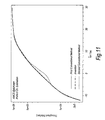
- Fig. 11 shows the corresponding results for the three methods, again under single path conditions, but with the UE moving at a medium speed of 60kph.
- the AMCS method embodying the present invention avoids the undesirable dip in the second conventional method.
- Fig. 12 shows some results obtained under two-equal-gain path conditions for the three different methods, and also shows (for comparison purposes) the performance of the first conventional method and a method embodying the present invention for single-path conditions.
- the UE is assumed to be moving at 3kph as in Fig. 10.
- Fig. 13 shows results corresponding to Fig. 12 but for a UE moving at a very high speed of 120kph.
- a method embodying the present invention outperforms both the conventional methods, in particular the first conventional method (fixed thresholds) which has a significant performance dip for downlink channel qualities between +4 and +24dB.
- This modification relates to the operations carried out in step S7 in Fig. 8.
- the UE also takes account of the CRC result in deciding the MCS level.
- Fig. 14 shows the threshold value Th02 used for selecting between MCS5 and MCS6, and the threshold value Th03 used for selecting between MCS6 and MCS8. Assume that the threshold values have been adjusted as necessary in step S5 or S6 or maintained unchanged in step S3 and that the current MCS level is MCS6.
- the MCS level is maintained unchanged in step S7.
- the MCS level is reduced from its current level MCS6 to a lower level MCS5.
- the MCS level is not automatically increased to MCS8 as in step S7 as previously described. Instead, the MCS level is maintained at its current level MCS6 when the CRC result is a failure, and only increased to MCS8 when the CRC result is a pass. In this way, selection of a higher MCS level, although suggested by the threshold value comparison, is prevented if the signal is not received successfully.
- the value ⁇ (or pair of values ⁇ 1 and ⁇ 2 ) can be different for each threshold value.
- a typical value of ⁇ is 1dB.
- Fig. 7, discussed in the introduction showed that when the path conditions are two equal-gain paths, and the fading model is a Rayleigh fading model, MCS6 always achieves a greater throughput than MCS8.
- the threshold value Th03 for selecting between MCS6 and MCS8 is redundant, which is equivalent to it having an infinite value. This suggests that Th03 can vary in a very wide range. In this case ⁇ 2 for Th03 can be chosen to be arbitrarily large or even infinite.
- the target frame error rate may be different for each different threshold value.
- a FER value of around 10 to 15% may be considered typical.
- the target FER could alternatively be a target FER value for the currently-selected MCS level, for example a target value for a quality measure in the middle of the band of quality measures over which that MCS level is selected.
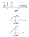
- ⁇ Up ⁇ Up 0 Max ⁇ a , b (
- a>0 a sensible value could be 0.25 to 1) and b ⁇ 0.
- Equation (3) results in a relationship between ⁇ Up and the difference between SIR and Thx as shown in Fig. 15(B). Equation (1) may be used to set ⁇ Down in this case also.
- Equations (2) and (3) have the effect of increasing ⁇ Up (and ⁇ Down) when the downlink channel quality measure becomes closer to one of the current threshold values.
- a first step S10 the UE produces a measure of downlink channel quality and also carries out a cyclic redundancy check on the current frame of the HS-DSCH.
- the downlink signal quality measure and the CRC result are reported by the UE to the base station via the HS-DPCCH.
- the base station then carries out steps S11 to S15, which correspond respectively to the steps S2 to S6 in Fig. 6, except that the operations are in this case carried out in the base station rather than in the UE.
- step S16 the base station selects the MCS level for the next downlink frame based on the threshold values (in the same way as the UE did in step S7 in Fig. 8).
- the MCS selection made according to the downlink channel quality measure may be overridden by the base station, for example depending on the amount of data waiting at the base station for transmission to the UE concerned.
- Quadrature phase shift keying has 2 bits per symbol
- 8 phase shift keying (8PSK) has 3 bits per symbol
- 16 quadrature amplitude amplitude modulation (16QAM) has 4 bits per symbol
- 64 quadrature amplitude amplitude modulation 64QAM has 6 bits per symbol.
- QPSK Quadrature phase shift keying
- 8PSK 8 phase shift keying
- 16QAM 16 quadrature amplitude amplitude modulation
- 64QAM 64 quadrature amplitude amplitude modulation
- Each scheme results in 2 ⁇ n constellation points, where n is the number of bits per symbol.
- the constellation points in I-Q signal space are shown for 8PSK, 16QAM and 64QAM in Figures 18(A) to (C) respectively.
- TDMA time-division multiple access
- WDMA wavelength-division multiple access
- FDMA frequency-division multiple access
- SDMA space-division multiple access
- DSP digital signal processor
Priority Applications (2)
| Application Number | Priority Date | Filing Date | Title |
|---|---|---|---|
| EP08164604A EP2007054A1 (fr) | 2002-07-30 | 2003-07-01 | Modulation et codage adaptatifs |
| EP06120301A EP1729434A3 (fr) | 2002-07-30 | 2003-07-01 | Modulation et codage adaptatifs |
Applications Claiming Priority (2)
| Application Number | Priority Date | Filing Date | Title |
|---|---|---|---|
| GB0217654A GB2391431A (en) | 2002-07-30 | 2002-07-30 | Adaptive modulation and coding method |
| GB0217654 | 2002-07-30 |
Related Child Applications (1)
| Application Number | Title | Priority Date | Filing Date |
|---|---|---|---|
| EP06120301A Division EP1729434A3 (fr) | 2002-07-30 | 2003-07-01 | Modulation et codage adaptatifs |
Publications (2)
| Publication Number | Publication Date |
|---|---|
| EP1387517A1 true EP1387517A1 (fr) | 2004-02-04 |
| EP1387517B1 EP1387517B1 (fr) | 2006-09-20 |
Family
ID=9941386
Family Applications (3)
| Application Number | Title | Priority Date | Filing Date |
|---|---|---|---|
| EP06120301A Withdrawn EP1729434A3 (fr) | 2002-07-30 | 2003-07-01 | Modulation et codage adaptatifs |
| EP08164604A Withdrawn EP2007054A1 (fr) | 2002-07-30 | 2003-07-01 | Modulation et codage adaptatifs |
| EP03254196A Expired - Fee Related EP1387517B1 (fr) | 2002-07-30 | 2003-07-01 | Modulation et codage adaptatifs |
Family Applications Before (2)
| Application Number | Title | Priority Date | Filing Date |
|---|---|---|---|
| EP06120301A Withdrawn EP1729434A3 (fr) | 2002-07-30 | 2003-07-01 | Modulation et codage adaptatifs |
| EP08164604A Withdrawn EP2007054A1 (fr) | 2002-07-30 | 2003-07-01 | Modulation et codage adaptatifs |
Country Status (5)
| Country | Link |
|---|---|
| US (6) | US20040022177A1 (fr) |
| EP (3) | EP1729434A3 (fr) |
| JP (1) | JP4287216B2 (fr) |
| DE (1) | DE60308457T2 (fr) |
| GB (1) | GB2391431A (fr) |
Cited By (7)
| Publication number | Priority date | Publication date | Assignee | Title |
|---|---|---|---|---|
| EP1505756A2 (fr) | 2003-07-31 | 2005-02-09 | Fujitsu Limited | Modulation et codage adaptatifs |
| WO2006105522A2 (fr) * | 2005-03-30 | 2006-10-05 | Intel Corporation | Seuillage adaptatif sur une sous-porteuse |
| WO2008014638A1 (fr) * | 2006-07-27 | 2008-02-07 | Utstarcom Telecom Co., Ltd. | Procédé de calcul de d'indice de qualité de canal lors de la période d'accès de paquets en liaison descendante à grande vitesse (hspda) ne transmettant pas dans un système utra tdd hcr, et équipement d'utilisateur terminal mettant en œuvre ledit procédé et système de co |
| WO2009152271A3 (fr) * | 2008-06-11 | 2010-03-18 | Qualcomm Incorporated | Appareil et procédé de contrôle d'erreur de canal de multiplexage non exclusif de canaux de commande |
| CN102868491A (zh) * | 2005-09-30 | 2013-01-09 | 富士通株式会社 | 基站和用于从传送站接收控制信道信息的用户终端 |
| CN101743710B (zh) * | 2007-06-25 | 2013-09-04 | 松下电器产业株式会社 | 通信装置、集成电路、传输速率控制方法及传输速率控制程序 |
| EP2984766A4 (fr) * | 2013-03-22 | 2016-11-30 | Ericsson Telefon Ab L M | Procédés, dispositifs mobiles et n uds pour une utilisation dans un réseau de communication mobile |
Families Citing this family (55)
| Publication number | Priority date | Publication date | Assignee | Title |
|---|---|---|---|---|
| JP3717913B2 (ja) * | 2002-12-27 | 2005-11-16 | 三洋電機株式会社 | 無線装置 |
| JP4250002B2 (ja) * | 2003-03-05 | 2009-04-08 | 富士通株式会社 | 適応型変調伝送システム及び適応型変調制御方法 |
| US20090080788A1 (en) * | 2003-04-17 | 2009-03-26 | Droplet Technology, Inc. | Multiple Technique Entropy Coding System And Method |
| WO2004107695A1 (fr) * | 2003-05-27 | 2004-12-09 | Nec Corporation | Dispositif de communication de donnees choisissant un procede de modulation a valeur seuil appropriee en modulation adaptative |
| US7406070B2 (en) * | 2003-10-09 | 2008-07-29 | Telefonaktiebolaget L M Ericsson (Publ) | Adaptive threshold for HS-SCCH part 1 decoding |
| EP1681883A4 (fr) * | 2003-10-31 | 2011-06-15 | Kyocera Corp | Procede de determination du debit de transmission, appareil de station de base et appareil de terminal associes |
| JP2005142923A (ja) * | 2003-11-07 | 2005-06-02 | Matsushita Electric Ind Co Ltd | 無線通信装置及びmcs決定方法 |
| WO2005050875A1 (fr) * | 2003-11-19 | 2005-06-02 | Samsung Electronics Co., Ltd. | Dispositif et procede d'emission et de reception d'informations a commande commune dans un systeme de communication sans fil |
| GB2410152B (en) * | 2004-01-15 | 2006-03-22 | Toshiba Kk | Radio communications system using adaptive modulation, radio transmission apparatus and radio receiving apparatus |
| JP4421935B2 (ja) * | 2004-04-30 | 2010-02-24 | 株式会社エヌ・ティ・ティ・ドコモ | 無線基地局装置及び無線通信制御方法 |
| US7979072B2 (en) * | 2004-06-04 | 2011-07-12 | Nortel Networks Limited | Method and system for soft handoff in mobile broadband systems |
| US7447516B2 (en) | 2004-06-09 | 2008-11-04 | Samsung Electronics Co., Ltd. | Method and apparatus for data transmission in a mobile telecommunication system supporting enhanced uplink service |
| KR100772369B1 (ko) * | 2004-07-13 | 2007-11-01 | 삼성전자주식회사 | 재전송 제어 방법 및 장치 |
| SE0402372D0 (sv) | 2004-09-30 | 2004-09-30 | Ericsson Telefon Ab L M | Signal coding |
| SE528213C3 (sv) * | 2004-09-30 | 2006-10-31 | Ericsson Telefon Ab L M | Förfaranden och arrangemang för adaptiva trösklar vid val av kodek |
| CN100353722C (zh) * | 2004-11-17 | 2007-12-05 | 华为技术有限公司 | 一种链路自适应的实现方法 |
| WO2006075870A1 (fr) * | 2005-01-11 | 2006-07-20 | Samsung Electronics Co., Ltd. | Procede et systeme pour indiquer une repartition de rafales de donnees dans un systeme de radiocommunications |
| US20060268762A1 (en) * | 2005-05-25 | 2006-11-30 | Francis Dominique | Method of path monitoring in a wireless communication system |
| KR20070033115A (ko) * | 2005-09-20 | 2007-03-26 | 삼성전자주식회사 | 광대역 무선 접속 통신 시스템에서 적응 변조 및 부호화레벨 할당 시스템 및 방법 |
| CN101273646A (zh) | 2005-09-22 | 2008-09-24 | 夏普株式会社 | 通信终端装置、通信控制装置、通信系统以及通信方法 |
| US7868874B2 (en) | 2005-11-15 | 2011-01-11 | Synaptics Incorporated | Methods and systems for detecting a position-based attribute of an object using digital codes |
| JP4818803B2 (ja) * | 2006-05-01 | 2011-11-16 | 株式会社エヌ・ティ・ティ・ドコモ | 可変tti長制御に基づく無線通信方法および無線通信装置 |
| JP2007325142A (ja) * | 2006-06-05 | 2007-12-13 | Sony Corp | 通信システム、受信装置、送信モード提案方法およびプログラム |
| CN102724732B (zh) * | 2006-07-04 | 2015-04-15 | 株式会社日立制作所 | 自组织网络的构筑方法 |
| WO2008024056A1 (fr) * | 2006-08-21 | 2008-02-28 | Telefonaktiebolaget L M Ericsson (Publ) | Procédé et moyen d'adaptation d'une transmission de données codées |
| KR20080024292A (ko) * | 2006-09-13 | 2008-03-18 | 삼성전자주식회사 | 휴대용 단말기의 셀 재선택 장치 및 방법 |
| US7702029B2 (en) * | 2006-10-02 | 2010-04-20 | Freescale Semiconductor, Inc. | MIMO precoding enabling spatial multiplexing, power allocation and adaptive modulation and coding |
| WO2008054735A1 (fr) | 2006-10-30 | 2008-05-08 | Interdigital Technology Corporation | Procédé et appareil de codage et de décodage de données de canal de commande partagé haut débit |
| US20090323641A1 (en) * | 2006-11-10 | 2009-12-31 | Panasonic Corporation | Radio communication mobile station device and mcs selection method |
| US8098601B2 (en) * | 2007-03-23 | 2012-01-17 | Research In Motion Limited | Slow adaptation of modulation and coding for packet transmission |
| MX2010004691A (es) * | 2007-10-29 | 2010-08-04 | Interdigital Patent Holdings | Manejo de respuestas de canal de acceso aleatorio. |
| ES2373240T3 (es) * | 2007-12-20 | 2012-02-01 | Panasonic Corporation | Señalización de canal de control usando un campo de señalización común para el formato de transporte y la versión de redundancia. |
| WO2009142564A1 (fr) * | 2008-05-23 | 2009-11-26 | Telefonaktiebolaget L M Ericsson (Publ) | Procédé d'adaptation de liaison avec une marge de qualité du signal en fonction la largeur de bande |
| TWI435561B (zh) * | 2008-08-11 | 2014-04-21 | Inst Information Industry | 多輸入多輸出天線系統、用於該多輸入多輸出天線系統之信號傳輸方法、信號傳輸裝置、電腦可讀取紀錄媒體及電腦程式產品 |
| US8611288B1 (en) | 2009-03-05 | 2013-12-17 | Marvell International Ltd | Systems and methods for link adaptation in wireless communication systems |
| US8982803B1 (en) * | 2009-03-05 | 2015-03-17 | Marvell International Ltd. | Systems and methods for link adaption in wireless communication systems |
| KR101147915B1 (ko) * | 2009-03-31 | 2012-05-24 | 경희대학교 산학협력단 | 적응 멀티캐스트/브로드캐스트 서비스 장치 및 방법 |
| US8189525B2 (en) * | 2009-06-19 | 2012-05-29 | Clearwire Ip Holdings Llc | Solution for INE/HO LB bottle neck |
| US8175051B2 (en) | 2009-05-29 | 2012-05-08 | Clearwire Ip Holdings Llc | Hybrid scheme for DL link adaptation |
| JP2010278928A (ja) * | 2009-05-29 | 2010-12-09 | Fujitsu Ltd | 無線端末、無線基地局、及び無線通信方法、 |
| JP5031009B2 (ja) * | 2009-09-15 | 2012-09-19 | 株式会社エヌ・ティ・ティ・ドコモ | 無線基地局及び移動通信方法 |
| US8340578B2 (en) | 2009-10-05 | 2012-12-25 | Apple Inc. | Methods and apparatus for enhanced coexistence algorithms in wireless systems |
| US8693569B2 (en) | 2009-10-19 | 2014-04-08 | Apple Inc. | Methods and apparatus for dynamic wireless device coexistence |
| US20110305209A1 (en) * | 2010-03-09 | 2011-12-15 | Qualcomm Incorporated | Rate adaptation for sdma |
| CN102347816B (zh) * | 2010-07-30 | 2014-08-13 | 中兴通讯股份有限公司 | 一种调制编码方式选择方法及装置 |
| JP5658954B2 (ja) * | 2010-09-15 | 2015-01-28 | 株式会社日立国際電気 | 無線通信装置 |
| US8599709B2 (en) | 2011-02-10 | 2013-12-03 | Apple Inc. | Methods and apparatus for wireless coexistence based on transceiver chain emphasis |
| WO2013025145A1 (fr) * | 2011-08-12 | 2013-02-21 | Telefonaktiebolaget L M Ericsson (Publ) | Nœud de réseau radio, équipement utilisateur et leurs procédés |
| US8995929B2 (en) * | 2011-12-06 | 2015-03-31 | Apple Inc. | Methods and apparatus for wireless optimization based on platform configuration and use cases |
| US8995553B2 (en) | 2012-06-08 | 2015-03-31 | Apple Inc. | Methods and apparatus for mitigating interference in aggressive form factor designs |
| CN103532659B (zh) * | 2012-07-03 | 2017-03-29 | 京信通信系统(广州)有限公司 | 一种确定编码方案码本的方法以及装置 |
| WO2014139089A1 (fr) * | 2013-03-12 | 2014-09-18 | Empire Technology Development Llc | Stabilité système à amélioration auto-adaptative |
| CN104811983B (zh) | 2014-01-24 | 2018-03-27 | 国际商业机器公司 | 自适应调制编码方法和装置 |
| US10924203B1 (en) * | 2019-07-26 | 2021-02-16 | Hughes Network Systems, Llc | On-the-fly inroute adaptive modulation |
| US11864234B2 (en) * | 2019-08-08 | 2024-01-02 | Qualcomm Incorporated | Beam-based channel access procedures |
Citations (1)
| Publication number | Priority date | Publication date | Assignee | Title |
|---|---|---|---|---|
| WO2000041318A1 (fr) * | 1999-01-06 | 2000-07-13 | University Of Southampton | Transmission adaptative de donnees, salve par salve, au moyen d'une seule porteuse |
Family Cites Families (28)
| Publication number | Priority date | Publication date | Assignee | Title |
|---|---|---|---|---|
| JP2832213B2 (ja) | 1989-01-30 | 1998-12-09 | 日本電信電話株式会社 | 光学ガラスの製造方法 |
| SE467332B (sv) * | 1990-06-21 | 1992-06-29 | Ericsson Telefon Ab L M | Foerfarande foer effektreglering i ett digitalt mobiltelefonisystem |
| EP0892963A1 (fr) * | 1996-01-26 | 1999-01-27 | David E. Patterson | Procede pour creer une bibliotheque moleculaire virtuelle et procede pour y faire des recherches, en utilisant des descripteurs valides de structure moleculaire |
| US6108374A (en) * | 1997-08-25 | 2000-08-22 | Lucent Technologies, Inc. | System and method for measuring channel quality information |
| US6167031A (en) * | 1997-08-29 | 2000-12-26 | Telefonaktiebolaget Lm Ericsson (Publ) | Method for selecting a combination of modulation and channel coding schemes in a digital communication system |
| US5946346A (en) * | 1997-10-07 | 1999-08-31 | Motorola, Inc. | Method and system for generating a power control command in a wireless communication system |
| US6034971A (en) * | 1998-06-30 | 2000-03-07 | Motorola, Inc. | Method and apparatus for controlling communication system capacity |
| US6865233B1 (en) * | 1999-02-19 | 2005-03-08 | Telefonaktiebolaget Lm Ericsson (Publ) | Method and system for control signalling enabling flexible link adaptation in a radiocommunication system |
| US6657954B1 (en) * | 1999-03-31 | 2003-12-02 | International Business Machines Corporation | Adapting receiver thresholds to improve rate-based flow control |
| US6385462B1 (en) * | 2000-05-26 | 2002-05-07 | Motorola, Inc. | Method and system for criterion based adaptive power allocation in a communication system with selective determination of modulation and coding |
| SE517030C2 (sv) * | 2000-06-06 | 2002-04-02 | Ericsson Telefon Ab L M | Metod och anordning för val av modulerings- och kodningsregler i ett radiokommunikationssystem |
| JP2001358692A (ja) * | 2000-06-14 | 2001-12-26 | Nec Corp | 直交周波数分割多重変復調回路 |
| EP1176749A3 (fr) * | 2000-06-20 | 2005-07-13 | Matsushita Electric Industrial Co., Ltd. | Système de radiocommunication |
| JP3426200B2 (ja) * | 2000-08-02 | 2003-07-14 | 松下電器産業株式会社 | 通信端末装置および無線通信方法 |
| JP3821636B2 (ja) * | 2000-08-21 | 2006-09-13 | 松下電器産業株式会社 | 通信端末装置、基地局装置および無線通信方法 |
| US6701129B1 (en) | 2000-09-27 | 2004-03-02 | Nortel Networks Limited | Receiver based adaptive modulation scheme |
| ES2575979T3 (es) | 2000-11-16 | 2016-07-04 | Sony Corporation | Aparato de comunicación |
| US6940915B2 (en) | 2000-11-30 | 2005-09-06 | Nokia Mobile Phones Ltd. | Adaptive learning method and system to adaptive modulation |
| GB0108516D0 (en) * | 2001-04-04 | 2001-05-23 | Nokia Corp | Power control |
| US6751187B2 (en) * | 2001-05-17 | 2004-06-15 | Qualcomm Incorporated | Method and apparatus for processing data for transmission in a multi-channel communication system using selective channel transmission |
| JP4016647B2 (ja) * | 2001-05-17 | 2007-12-05 | 日本電気株式会社 | 移動通信システム、基地局、移動局及びそれらに用いるしきい値設定方法並びにそのプログラム |
| US7043210B2 (en) * | 2001-06-05 | 2006-05-09 | Nortel Networks Limited | Adaptive coding and modulation |
| US20020183010A1 (en) * | 2001-06-05 | 2002-12-05 | Catreux Severine E. | Wireless communication systems with adaptive channelization and link adaptation |
| US6944460B2 (en) * | 2001-06-07 | 2005-09-13 | Telefonaktiebolaget L M Ericsson (Publ) | System and method for link adaptation in communication systems |
| AU2002314411A1 (en) * | 2001-06-25 | 2003-01-08 | Nokia Corporation | Optimization of mcs and multicode with tfci signaling |
| KR100493079B1 (ko) * | 2001-11-02 | 2005-06-02 | 삼성전자주식회사 | 고속 순방향 패킷 접속 방식을 사용하는 광대역 부호 분할다중 접속 통신 시스템에서 순방향 채널 품질을 보고하는장치 및 방법 |
| US7126996B2 (en) * | 2001-12-28 | 2006-10-24 | Motorola, Inc. | Adaptive transmission method |
| US6683916B1 (en) * | 2002-07-17 | 2004-01-27 | Philippe Jean-Marc Sartori | Adaptive modulation/coding and power allocation system |
-
2002
- 2002-07-30 GB GB0217654A patent/GB2391431A/en not_active Withdrawn
-
2003
- 2003-07-01 EP EP06120301A patent/EP1729434A3/fr not_active Withdrawn
- 2003-07-01 EP EP08164604A patent/EP2007054A1/fr not_active Withdrawn
- 2003-07-01 EP EP03254196A patent/EP1387517B1/fr not_active Expired - Fee Related
- 2003-07-01 DE DE60308457T patent/DE60308457T2/de not_active Expired - Lifetime
- 2003-07-29 JP JP2003282158A patent/JP4287216B2/ja not_active Expired - Lifetime
- 2003-07-29 US US10/629,386 patent/US20040022177A1/en not_active Abandoned
-
2007
- 2007-04-06 US US11/783,156 patent/US8488520B2/en not_active Expired - Fee Related
- 2007-04-06 US US11/783,158 patent/US20070189211A1/en not_active Abandoned
- 2007-04-06 US US11/783,155 patent/US8121072B2/en not_active Expired - Fee Related
- 2007-04-06 US US11/783,159 patent/US8576771B2/en not_active Expired - Fee Related
- 2007-04-06 US US11/783,157 patent/US8665781B2/en not_active Expired - Fee Related
Patent Citations (1)
| Publication number | Priority date | Publication date | Assignee | Title |
|---|---|---|---|---|
| WO2000041318A1 (fr) * | 1999-01-06 | 2000-07-13 | University Of Southampton | Transmission adaptative de donnees, salve par salve, au moyen d'une seule porteuse |
Non-Patent Citations (1)
| Title |
|---|
| NEC, TELECOM MODUS: "Selection of MCS levels in HSDPA", TSG-RAN WORKING GROUP 1, 21 May 2001 (2001-05-21) - 25 May 2001 (2001-05-25), Busan, Korea, pages 1 - 4, XP002262799 * |
Cited By (17)
| Publication number | Priority date | Publication date | Assignee | Title |
|---|---|---|---|---|
| EP1505756A2 (fr) | 2003-07-31 | 2005-02-09 | Fujitsu Limited | Modulation et codage adaptatifs |
| EP1505756B1 (fr) * | 2003-07-31 | 2009-03-25 | Fujitsu Limited | Modulation et codage adaptatifs |
| US7590181B2 (en) | 2003-07-31 | 2009-09-15 | Fujitsu Limited | Adaptive modulation and coding |
| US7693224B2 (en) | 2005-03-30 | 2010-04-06 | Intel Corporation | Subcarrier adaptive thresholding |
| WO2006105522A2 (fr) * | 2005-03-30 | 2006-10-05 | Intel Corporation | Seuillage adaptatif sur une sous-porteuse |
| WO2006105522A3 (fr) * | 2005-03-30 | 2007-04-19 | Intel Corp | Seuillage adaptatif sur une sous-porteuse |
| CN102868491A (zh) * | 2005-09-30 | 2013-01-09 | 富士通株式会社 | 基站和用于从传送站接收控制信道信息的用户终端 |
| CN102882649A (zh) * | 2005-09-30 | 2013-01-16 | 富士通株式会社 | 通信方法 |
| CN102868491B (zh) * | 2005-09-30 | 2015-07-08 | 富士通株式会社 | 基站和用于从传送站接收控制信道信息的用户终端 |
| CN102882649B (zh) * | 2005-09-30 | 2015-09-30 | 富士通株式会社 | 通信方法 |
| WO2008014638A1 (fr) * | 2006-07-27 | 2008-02-07 | Utstarcom Telecom Co., Ltd. | Procédé de calcul de d'indice de qualité de canal lors de la période d'accès de paquets en liaison descendante à grande vitesse (hspda) ne transmettant pas dans un système utra tdd hcr, et équipement d'utilisateur terminal mettant en œuvre ledit procédé et système de co |
| CN101743710B (zh) * | 2007-06-25 | 2013-09-04 | 松下电器产业株式会社 | 通信装置、集成电路、传输速率控制方法及传输速率控制程序 |
| WO2009152271A3 (fr) * | 2008-06-11 | 2010-03-18 | Qualcomm Incorporated | Appareil et procédé de contrôle d'erreur de canal de multiplexage non exclusif de canaux de commande |
| RU2477002C2 (ru) * | 2008-06-11 | 2013-02-27 | Квэлкомм Инкорпорейтед | Устройство и способ для управления ошибкой канала неисключительного мультиплексирования для каналов управления |
| US8498243B2 (en) | 2008-06-11 | 2013-07-30 | Qualcomm Incorporated | Apparatus and method for channel error control of non-exclusive multiplexing for control channels |
| EP2984766A4 (fr) * | 2013-03-22 | 2016-11-30 | Ericsson Telefon Ab L M | Procédés, dispositifs mobiles et n uds pour une utilisation dans un réseau de communication mobile |
| US9520963B2 (en) | 2013-03-22 | 2016-12-13 | Telefonaktiebolaget Lm Ericsson (Publ) | Modulation and coding scheme selection for link adaptation |
Also Published As
| Publication number | Publication date |
|---|---|
| GB0217654D0 (en) | 2002-09-11 |
| GB2391431A (en) | 2004-02-04 |
| EP1729434A3 (fr) | 2007-03-28 |
| US20070189210A1 (en) | 2007-08-16 |
| JP2004064797A (ja) | 2004-02-26 |
| US8576771B2 (en) | 2013-11-05 |
| EP1387517B1 (fr) | 2006-09-20 |
| EP2007054A1 (fr) | 2008-12-24 |
| US20070189208A1 (en) | 2007-08-16 |
| DE60308457D1 (de) | 2006-11-02 |
| JP4287216B2 (ja) | 2009-07-01 |
| US8121072B2 (en) | 2012-02-21 |
| US8488520B2 (en) | 2013-07-16 |
| US20070189209A1 (en) | 2007-08-16 |
| US20070189212A1 (en) | 2007-08-16 |
| EP1729434A2 (fr) | 2006-12-06 |
| US20070189211A1 (en) | 2007-08-16 |
| US20040022177A1 (en) | 2004-02-05 |
| US8665781B2 (en) | 2014-03-04 |
| DE60308457T2 (de) | 2006-12-28 |
Similar Documents
| Publication | Publication Date | Title |
|---|---|---|
| EP1387517B1 (fr) | Modulation et codage adaptatifs | |
| US7590181B2 (en) | Adaptive modulation and coding | |
| US8204023B2 (en) | CQI reporting method and apparatus for mobile telecommunication system | |
| US20050213505A1 (en) | Communication device and data retransmission control method | |
| US20040252670A1 (en) | Adaptive power margin adjustment for a 1xEV-DV system | |
| US20040179480A1 (en) | Method and system for estimating parameters of a link for data transmission in a communication system | |
| US20100014487A1 (en) | Method and system for a data transmission in a communication system | |
| US20040038697A1 (en) | Method and system for a data transmission in a communication system | |
| US20040181569A1 (en) | Method and system for a data transmission in a communication system | |
| US7400674B2 (en) | Method and device for controlling transmission of sets of data | |
| EP1685739A1 (fr) | Transmission en liaison retour tdm/ofdm/cdm hybride | |
| KR20030092894A (ko) | 고속 순방향 패킷 접속 방식을 사용하는 통신 시스템에서순방향 채널 품질을 보고하기 위한 채널 품질 보고 주기결정 장치 및 방법 | |
| EP1602187B1 (fr) | Methode et systeme pour une transmission de donnees dans un systeme de communication | |
| EP1540983A2 (fr) | Methode et systeme pour une transmission de donnees dans un systeme de communication | |
| JP4205937B2 (ja) | 制御局装置 | |
| JP4113417B2 (ja) | 基地局装置および送信方法 |
Legal Events
| Date | Code | Title | Description |
|---|---|---|---|
| PUAI | Public reference made under article 153(3) epc to a published international application that has entered the european phase |
Free format text: ORIGINAL CODE: 0009012 |
|
| AK | Designated contracting states |
Kind code of ref document: A1 Designated state(s): AT BE BG CH CY CZ DE DK EE ES FI FR GB GR HU IE IT LI LU MC NL PT RO SE SI SK TR |
|
| AX | Request for extension of the european patent |
Extension state: AL LT LV MK |
|
| 17P | Request for examination filed |
Effective date: 20040614 |
|
| 17Q | First examination report despatched |
Effective date: 20040811 |
|
| AKX | Designation fees paid |
Designated state(s): DE FR GB |
|
| GRAP | Despatch of communication of intention to grant a patent |
Free format text: ORIGINAL CODE: EPIDOSNIGR1 |
|
| GRAS | Grant fee paid |
Free format text: ORIGINAL CODE: EPIDOSNIGR3 |
|
| GRAA | (expected) grant |
Free format text: ORIGINAL CODE: 0009210 |
|
| AK | Designated contracting states |
Kind code of ref document: B1 Designated state(s): DE FR GB |
|
| REG | Reference to a national code |
Ref country code: GB Ref legal event code: FG4D |
|
| REF | Corresponds to: |
Ref document number: 60308457 Country of ref document: DE Date of ref document: 20061102 Kind code of ref document: P |
|
| ET | Fr: translation filed | ||
| PLBE | No opposition filed within time limit |
Free format text: ORIGINAL CODE: 0009261 |
|
| STAA | Information on the status of an ep patent application or granted ep patent |
Free format text: STATUS: NO OPPOSITION FILED WITHIN TIME LIMIT |
|
| 26N | No opposition filed |
Effective date: 20070621 |
|
| REG | Reference to a national code |
Ref country code: FR Ref legal event code: PLFP Year of fee payment: 13 |
|
| PGFP | Annual fee paid to national office [announced via postgrant information from national office to epo] |
Ref country code: DE Payment date: 20150624 Year of fee payment: 13 Ref country code: GB Payment date: 20150701 Year of fee payment: 13 |
|
| PGFP | Annual fee paid to national office [announced via postgrant information from national office to epo] |
Ref country code: FR Payment date: 20150629 Year of fee payment: 13 |
|
| REG | Reference to a national code |
Ref country code: DE Ref legal event code: R119 Ref document number: 60308457 Country of ref document: DE |
|
| GBPC | Gb: european patent ceased through non-payment of renewal fee |
Effective date: 20160701 |
|
| PG25 | Lapsed in a contracting state [announced via postgrant information from national office to epo] |
Ref country code: DE Free format text: LAPSE BECAUSE OF NON-PAYMENT OF DUE FEES Effective date: 20170201 Ref country code: FR Free format text: LAPSE BECAUSE OF NON-PAYMENT OF DUE FEES Effective date: 20160801 |
|
| REG | Reference to a national code |
Ref country code: FR Ref legal event code: ST Effective date: 20170331 |
|
| PG25 | Lapsed in a contracting state [announced via postgrant information from national office to epo] |
Ref country code: GB Free format text: LAPSE BECAUSE OF NON-PAYMENT OF DUE FEES Effective date: 20160701 |