EP1386717B1 - Threaded removable heater for a hot runner nozzle - Google Patents
Threaded removable heater for a hot runner nozzle Download PDFInfo
- Publication number
- EP1386717B1 EP1386717B1 EP03017780A EP03017780A EP1386717B1 EP 1386717 B1 EP1386717 B1 EP 1386717B1 EP 03017780 A EP03017780 A EP 03017780A EP 03017780 A EP03017780 A EP 03017780A EP 1386717 B1 EP1386717 B1 EP 1386717B1
- Authority
- EP
- European Patent Office
- Prior art keywords
- nozzle
- heater
- sleeve
- heater sleeve
- nozzle body
- Prior art date
- Legal status (The legal status is an assumption and is not a legal conclusion. Google has not performed a legal analysis and makes no representation as to the accuracy of the status listed.)
- Expired - Lifetime
Links
- 238000010438 heat treatment Methods 0.000 claims description 61
- 238000001746 injection moulding Methods 0.000 claims description 47
- 239000000155 melt Substances 0.000 claims description 18
- 239000000463 material Substances 0.000 claims description 17
- 238000002347 injection Methods 0.000 claims description 15
- 239000007924 injection Substances 0.000 claims description 15
- 238000000034 method Methods 0.000 claims description 4
- 230000006698 induction Effects 0.000 claims description 3
- 239000004020 conductor Substances 0.000 description 6
- 230000013011 mating Effects 0.000 description 6
- 238000000429 assembly Methods 0.000 description 4
- 230000000712 assembly Effects 0.000 description 4
- 238000001816 cooling Methods 0.000 description 4
- 238000000465 moulding Methods 0.000 description 4
- RYGMFSIKBFXOCR-UHFFFAOYSA-N Copper Chemical compound [Cu] RYGMFSIKBFXOCR-UHFFFAOYSA-N 0.000 description 3
- 229910000881 Cu alloy Inorganic materials 0.000 description 3
- 229910000831 Steel Inorganic materials 0.000 description 3
- DMFGNRRURHSENX-UHFFFAOYSA-N beryllium copper Chemical compound [Be].[Cu] DMFGNRRURHSENX-UHFFFAOYSA-N 0.000 description 3
- 229910052802 copper Inorganic materials 0.000 description 3
- 239000010949 copper Substances 0.000 description 3
- 238000004519 manufacturing process Methods 0.000 description 3
- 239000012768 molten material Substances 0.000 description 3
- 239000010959 steel Substances 0.000 description 3
- MCMNRKCIXSYSNV-UHFFFAOYSA-N Zirconium dioxide Chemical compound O=[Zr]=O MCMNRKCIXSYSNV-UHFFFAOYSA-N 0.000 description 2
- 238000004891 communication Methods 0.000 description 2
- 238000009434 installation Methods 0.000 description 2
- 239000012774 insulation material Substances 0.000 description 2
- ORQBXQOJMQIAOY-UHFFFAOYSA-N nobelium Chemical compound [No] ORQBXQOJMQIAOY-UHFFFAOYSA-N 0.000 description 2
- 239000000243 solution Substances 0.000 description 2
- 125000006850 spacer group Chemical group 0.000 description 2
- OKTJSMMVPCPJKN-UHFFFAOYSA-N Carbon Chemical compound [C] OKTJSMMVPCPJKN-UHFFFAOYSA-N 0.000 description 1
- 239000004809 Teflon Substances 0.000 description 1
- 229920006362 Teflon® Polymers 0.000 description 1
- 229910001069 Ti alloy Inorganic materials 0.000 description 1
- RTAQQCXQSZGOHL-UHFFFAOYSA-N Titanium Chemical compound [Ti] RTAQQCXQSZGOHL-UHFFFAOYSA-N 0.000 description 1
- 229920004695 VICTREX™ PEEK Polymers 0.000 description 1
- 238000005266 casting Methods 0.000 description 1
- 239000000919 ceramic Substances 0.000 description 1
- 238000010276 construction Methods 0.000 description 1
- 230000008878 coupling Effects 0.000 description 1
- 238000010168 coupling process Methods 0.000 description 1
- 238000005859 coupling reaction Methods 0.000 description 1
- 239000003989 dielectric material Substances 0.000 description 1
- 238000007710 freezing Methods 0.000 description 1
- 230000008014 freezing Effects 0.000 description 1
- 229910002804 graphite Inorganic materials 0.000 description 1
- 239000010439 graphite Substances 0.000 description 1
- 230000020169 heat generation Effects 0.000 description 1
- 239000011810 insulating material Substances 0.000 description 1
- 238000007726 management method Methods 0.000 description 1
- 229920003223 poly(pyromellitimide-1,4-diphenyl ether) Polymers 0.000 description 1
- 229920000642 polymer Polymers 0.000 description 1
- 238000007639 printing Methods 0.000 description 1
- 238000005507 spraying Methods 0.000 description 1
- 239000010936 titanium Substances 0.000 description 1
- 229910052719 titanium Inorganic materials 0.000 description 1
- 238000001771 vacuum deposition Methods 0.000 description 1
Images


Classifications
-
- B—PERFORMING OPERATIONS; TRANSPORTING
- B29—WORKING OF PLASTICS; WORKING OF SUBSTANCES IN A PLASTIC STATE IN GENERAL
- B29C—SHAPING OR JOINING OF PLASTICS; SHAPING OF MATERIAL IN A PLASTIC STATE, NOT OTHERWISE PROVIDED FOR; AFTER-TREATMENT OF THE SHAPED PRODUCTS, e.g. REPAIRING
- B29C45/00—Injection moulding, i.e. forcing the required volume of moulding material through a nozzle into a closed mould; Apparatus therefor
- B29C45/17—Component parts, details or accessories; Auxiliary operations
- B29C45/26—Moulds
- B29C45/27—Sprue channels ; Runner channels or runner nozzles
- B29C45/2737—Heating or cooling means therefor
-
- H—ELECTRICITY
- H05—ELECTRIC TECHNIQUES NOT OTHERWISE PROVIDED FOR
- H05B—ELECTRIC HEATING; ELECTRIC LIGHT SOURCES NOT OTHERWISE PROVIDED FOR; CIRCUIT ARRANGEMENTS FOR ELECTRIC LIGHT SOURCES, IN GENERAL
- H05B3/00—Ohmic-resistance heating
- H05B3/40—Heating elements having the shape of rods or tubes
- H05B3/42—Heating elements having the shape of rods or tubes non-flexible
- H05B3/46—Heating elements having the shape of rods or tubes non-flexible heating conductor mounted on insulating base
-
- B—PERFORMING OPERATIONS; TRANSPORTING
- B29—WORKING OF PLASTICS; WORKING OF SUBSTANCES IN A PLASTIC STATE IN GENERAL
- B29C—SHAPING OR JOINING OF PLASTICS; SHAPING OF MATERIAL IN A PLASTIC STATE, NOT OTHERWISE PROVIDED FOR; AFTER-TREATMENT OF THE SHAPED PRODUCTS, e.g. REPAIRING
- B29C45/00—Injection moulding, i.e. forcing the required volume of moulding material through a nozzle into a closed mould; Apparatus therefor
- B29C45/17—Component parts, details or accessories; Auxiliary operations
- B29C45/26—Moulds
- B29C45/27—Sprue channels ; Runner channels or runner nozzles
- B29C45/2737—Heating or cooling means therefor
- B29C2045/2743—Electrical heating element constructions
-
- B—PERFORMING OPERATIONS; TRANSPORTING
- B29—WORKING OF PLASTICS; WORKING OF SUBSTANCES IN A PLASTIC STATE IN GENERAL
- B29C—SHAPING OR JOINING OF PLASTICS; SHAPING OF MATERIAL IN A PLASTIC STATE, NOT OTHERWISE PROVIDED FOR; AFTER-TREATMENT OF THE SHAPED PRODUCTS, e.g. REPAIRING
- B29C45/00—Injection moulding, i.e. forcing the required volume of moulding material through a nozzle into a closed mould; Apparatus therefor
- B29C45/17—Component parts, details or accessories; Auxiliary operations
- B29C45/26—Moulds
- B29C45/27—Sprue channels ; Runner channels or runner nozzles
- B29C2045/2772—Means for fixing the nozzle to the manifold
Definitions
- the present invention relates generally to an injection molding apparatus and in particular to a removable heater for injection nozzles and manifolds.
- Heat generation and management of molten material in an injection molding apparatus is important for ensuring the production of high quality molded parts.
- Heating of the molten material is typically accomplished by locating several electrically powered heaters adjacent to the flow channel of the machine nozzle, the mold manifold and the hot runner nozzle.
- electrical heaters Several different types are available including coil heaters, band heaters, film heaters, heat pipes, induction heaters and cartridge heaters.
- the heaters are sometimes integrated or embedded into the nozzle housing in order to optimize the heat transfer to the molten material. Integrated electrical heaters are more expensive to manufacture and typically cannot be replaced without replacing the entire nozzle.
- a disadvantage of the known removable heaters in injection molding is that achieving efficient heat transfer between the heater and the nozzle can be difficult. Because the heater is a separate component, gaps can occur between the heater and the nozzle or manifold, any gap between these components reduces the efficiency of the heat transfer. The amount of contact between the heater and the nozzle or manifold must therefore be maximized. As a result, clamping solutions have been developed. Ideally, an optimum heater clamp would provide a good heat transfer from the heater to the nozzle irrespective of the actual temperature of the heater clamp. An ideal clamped heater would operate perfectly in hot conditions and would continue to operate perfectly regardless of temperature changes or variations from higher temperatures to lower temperatures. This means that the temperature fluctuation of the heater would not affect the clamping force between the heater and the nozzle.
- a further disadvantage of known removable heaters is that they often require additional space to accommodate a locking mechanism. This is a problem in high cavitation molding applications where the space between the adjacent nozzle is minimized.
- a prior art clamp comprising a cylindrical heating sleeve 4 is shown.
- the heating sleeve 4 which includes heating elements 5 embedded therein, surrounds a nozzle body 6 to transfer heat thereto.
- the heating sleeve 4 includes an axial gap that provides a spring like characteristic.
- a clamping mechanism 7 having a screw 8 is provided for tightening the heating sleeve 4 about the nozzle body 6.
- the heating sleeve 4 is installed and clamped around the nozzle body 6 when the nozzle body 6 is in the cold condition. During regular operation, heat expansion causes the nozzle body 6 and the heating sleeve 4 to expand radially, as indicated by arrows 9.
- the prior art solutions include several different clamping devices for exerting a compressing force on the heater in order to maintain contact between the nozzle body and the heater.
- U.S. Patent No. 3,849,630 describes an elongated heating device having a core with a helical groove in its outer surface and a heating element attached within this groove.
- the heating device further comprises a separately formed sleeve surrounding the core with a helical groove on its inner surface surrounding the heating element.
- EP 0 724 943 A1 relates to a nozzle with an externally heated tube.
- the heating system is designed as a preassembled tubular unit with a casted body embedding a heating coil. The tube is inserted into the tubular heating system.
- U.S. Patent No. 4,268,241 discloses a removable annular heating element that is maintained in position by a nut. The nut is threaded onto a threaded lower portion of the nozzle near the nozzle tip.
- GB 2 044 162 A1 describes a sprue bushing having an elongated inner core portion with an outer surface in the form of a helical ridge with rounded cross sections. An electrical heating element is located over the core portion and an outer shell portion is cast over them to form an integral sprue bushing unit.
- U.S. Patent No. 4,940,870 teaches an induction heating element for hot runner nozzles that includes a clamping sleeve having axial slots of various lengths.
- U.S. Patent No. 6,163,016 discloses a removable heater that is surrounded by a clamp. A pair of collars at opposing ends of the clamp are provided to compress the heater against the nozzle body.
- U.S. Patent No. 6,409,497 discloses a jacket-heating unit for a nozzle.
- the heating unit is surrounded by a sleeve that is flexible in the radial direction.
- a circular lock surrounds the sleeve and is rotatable between a released position and a clamped position.
- the sleeve and the circular lock include facing surfaces that have profiles that deviate from that of a cylindrical shell.
- an injection molding apparatus comprising a nozzle according to one of the claims 1 to 10;
- the present invention provides advantages in that the heater assembly is relatively easy to install and remove while the injection nozzle is in communication with the manifold.
- the contact between the threaded heater sleeve and the threaded nozzle body enables efficient heat transfer to occur. Furthermore, the clamping force between the heater assembly and the nozzle, or manifold, is maintained regardless of the temperature of the heater assembly.
- nozzles 20 can be used to feed either a single or a plurality of mold cavities 26.
- Manifold heaters 32 maintain the melt stream in the manifold 12 at a desired temperature and cooling channels (not shown) facilitate cooling of the mold cavities 26.
- the nozzle 20 of Figure 2 is referred to as a front mounted nozzle.
- the nozzle 20 includes a nozzle head 34, a nozzle body 36 and a nozzle tip 38.
- the nozzle head 34 is secured to the manifold by fasteners 40.
- a second mold plate 46 and a third mold plate 48 are layered between the nozzle head 34 and the first mold plate 28.
- the third mold plate 48 is coupled to the second mold plate 46 by fasteners 50.
- the fasteners 50 are typically threaded fasteners that are removable, as indicated by arrows 61.
- Mounting elements 52 are coupled to the third mold plate 48.
- the mounting elements 52 extend inwardly toward the nozzle 20 to locate the nozzle 20 relative to the third mold plate 48.
- the injection molding apparatus 10 is separable at parting lines 58 and 60, respectively.
- a heater assembly 80 surrounds the nozzle 20 to maintain the melt stream in the nozzle 20 at a desired temperature.
- the heater assembly 80 generally includes a heating element 84 that is coupled to an annular heater sleeve 86.
- An electrical connector 82 is provided for coupling the heater assembly 80 to a power source (not shown).
- the heater assembly 80 is removable from the nozzle 20 as will be described in greater detail in relation to Figures 3 to 6 .
- heater assemblies 80 can be used in conjunction with a single nozzle. These heater assemblies can be coupled to a single or multiple power sources. The heater assemblies 80 can be used to provide a varying temperature profile along the nozzle.
- access to the nozzle 20 is achieved by separating the first mold plate 28 from the third mold plate 48 along parting line 60. Fasteners 50 are then unscrewed and the third mold plate 48 is separated from the second mold plate 46. This allows the nozzle 20 to be exposed so that an operator is able to replace parts that are not operating properly, for example, such parts include nozzle tips 38, nozzle seals (not shown), removable heaters 80 and thermocouples (not shown).
- the injection molding apparatus 10 is re-assembled by performing the above steps in the reverse order.
- Front mounted nozzles allow an operator to gain access to the nozzle 20 from the mold side of the injection molding apparatus 10. Although this arrangement allows the operator to gain access to the nozzle 20, the nozzle 20 itself is not removable without removing the entire mold from the injection molding apparatus 10.
- U.S. Patent Nos. 6,343,925 , 6,164,954 and 6,220,851 which show various known nozzle designs.
- FIG. 3 An injection molding apparatus 10a having a nozzle 20a that screws into the manifold 12 is shown in Figure 3.
- Figure 3 shows another embodiment of the present invention in which like reference numerals represent like parts.
- Nozzle 20a of Figure 3 is also a front mounted nozzle, however, nozzle 20a is removable from the injection molding apparatus 10a.
- the nozzle head 34a includes threads (not shown) to mate with a manifold mounting nut 62 that is coupled to the manifold 12.
- the screw-in nozzle 20a can be easily unscrewed and removed by an operator from the mold side of the apparatus 10a.
- a heater assembly 80a according to another embodiment of the present invention is removable from the nozzle 20a. The heater assembly 80a can be removed when the nozzle 20a is mounted in the injection molding apparatus 10a or when the nozzle 20a has been removed from the injection molding apparatus 10a.
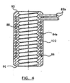
- the heater assembly 80a includes annular heater sleeve 86, shown in Figure 4 , having a threaded inner surface 88.
- the heater sleeve 86 includes a heater sleeve body 122 having a first end surface 90 and a second end surface 92.
- the heater sleeve 86 is sized to extend along a portion of the nozzle body 36a between the nozzle head 38a and the nozzle tip 38a of the hot runner nozzle 20a.
- the first end surface 90 and the second end surface 46 are generally parallel to one another.
- a coiled heating element 84a extends through the heater sleeve 86.
- the heater sleeve 86 according to the embodiment of Figure 4 is manufactured by a casting process so that the heating element 84a is fully embedded therein.
- An electrical connector 82a extends from the heater sleeve 86 and is coupled to a power source (not shown) to provide power to heat the heating element 84a.
- the heater sleeve 86 is comprised of a highly conductive material such as copper, beryllium copper or copper alloy. Alternatively, the heater sleeve 86 may be comprised of any suitable conductive material, such as steel.
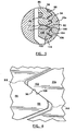
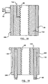
- the threaded inner surface 88 of the heater sleeve 86 engages a threaded outer surface 100 of the nozzle 20a.
- the threaded inner surface 88 can be seen to have a series of individual thread elements 94.
- Each thread element 94 includes a first surface 96, which is also referred to as a leading surface, and an opposing second surface 98, which is also referred to as a trailing surface
- the threaded outer surface 100 of the nozzle 20a similarly includes a series of individual nozzle thread elements 102.
- Each of the nozzle thread elements 102 includes a third surface 104 and an opposing fourth surface 106.
- the first surfaces 96, which are also referred to as leading surfaces, of the thread elements 94 of the heater sleeve 86 are directed towards the fourth surfaces 106 of the nozzle thread elements 102.
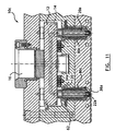
- a lock nut 108 includes a threaded inner surface 110 for engaging the threaded outer surface 100 of the hot runner nozzle 20a.
- the lock nut 108 includes a mating surface 112 for abutting the second surface 92 of the heater sleeve 86 and an opposing surface 114.
- the opposing surface 114 is directed towards the nozzle tip 38a of the hot runner nozzle 20a.
- the lock nut 108 is generally of conventional lock nut construction and is comprised of any suitable conductive material such as steel, copper, beryllium copper or copper alloy. In some cases, the nut 108 may be comprised of a less thermally conductive material such as titanium or titanium alloys.
- the nut 108 is comprised of an insulation material.
- Insulation materials include ceramics such as Zirconia, for example, polymides such as Vespel ⁇ , which is manufactured by Dupont, for example, polymers such as Teflon, which is manufactured by Dupont, or Peek TM , which is manufactured by Victrex , for example, or graphite.
- the magnitude of the clamping force generated between the threaded inner surface 88 of the heater sleeve 86 and the threaded outer surface of the nozzle 20a is influenced in part by the selection of the materials of the nozzle 20a and of the heater sleeve 86.
- a cut or slot is provided along the length of the heater sleeve 86. This slot provides the heater sleeve with further spring characteristics to vary the clamping force for specific molding applications.
- the heater assembly 34 is installed by screwing the heater sleeve 86 onto the hot runner nozzle 20a so that the threaded inner surface 88 of the heater sleeve 86 engages the threaded outer surface 100 of the hot runner nozzle 20a.
- the threaded outer surface 100 of the hot runner nozzle 20a provides a first engaging surface having a first profile.
- the threaded inner surface 88 of the heater sleeve 86 provides a second engaging surface having a second profile.
- the first and second profiles mesh to couple the heater sleeve 86 to the hot runner nozzle 20a.
- the lock nut 108 is then screwed onto the threaded outer surface 100 of the nozzle 20a.
- FIG. 7 another embodiment of a heater assembly 80b is shown.
- Heater assemblies 80b are coupled to nozzles 20a of an injection molding apparatus 10b, which is similar to injection molding apparatus 10a of Figure 3 .
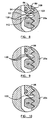
- the heater assembly 80b is similar to that shown in Figure 3 , with the addition of a pair of springs 120.
- the springs 120 are located between the mating surface 112 of the lock nut 108 and the second end surface 92 of the heater sleeve 86. As shown in Figure 8 , the springs 120 force the first surfaces 96 of the heater sleeve thread elements 94 into contact with the fourth surfaces 106 of the nozzle thread elements 102.
- the springs 120 are Belleville discs and are arranged to face one another.
- the embodiment of Figure 8 allows for relative movement between the lock nut 108 and the heater sleeve 86.
- the springs 120 provide an initial clamping force, or load, between the nozzle 20a and the heater sleeve 86.
- the springs 120 further compensate for the thermal expansion due to heating by ensuring that a pressure is continuously applied between the lock nut 108 and heater sleeve 86.
- the springs 120 also allow the heater sleeve to clamp onto the nozzle 20a during cold or variable conditions.
- Figures 13 and 14 show different spring arrangements that may be used in place of the spring arrangement of Figure 12.
- Figure 13 includes three springs 120 that are nested within one another. The larger diameter side of the springs 120 is directed toward the nozzle head 34a.
- Figure 14 includes a pair of springs 120 that are arranged to face one another.
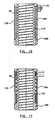
- second, third, fourth, fifth and sixth heater sleeves 186, 286, 386, 486 and 586, respectively, are shown.
- the heater sleeves 186, 286, 386, 486 and 586 can be used in place of the heater sleeve 86 in any of the disclosed heater assembly embodiments.
- the heater sleeve 186 of Figure 15 includes a coiled heating element 184 that is partially embedded into the outer surface of the heater sleeve body 122.
- a groove 124 is formed in the heater sleeve body 122 and the heating element 184 is pressed or brazed into the groove 124.
- the heater sleeve 486 of Figure 18 includes a film layer 130 that surrounds the heater sleeve body 122.
- a patterned electrical heating element is contained within the film layer 130.
- the film layer 130 is made of several layers of different materials. These film layers include dielectrics and thermal insulating materials. These film layers can be applied using known techniques such as spraying, printing or vacuum deposition. These layers can be applied directly on the nozzle or on a separate piece bonded or attached to the nozzle 20a.
- the heater sleeve 486 includes a threaded inner surface 88.
- the electrical connector 82 is coupled to the film layer 130 for mating with a power source (not shown).
- a thermocouple 132 is coupled to the heater sleeve 486 to measure the temperature of the nozzle 20a.
- the heater sleeve 586 of Figure 17 includes a plurality of cartridge heating elements 584 that are located using any means, such as through an interference fit into holes 134 provided in the heater sleeve body 122.
- Each cartridge heating element 584 includes an electrical connector 82 for mating with a power source (not shown).
- a thermocouple 136 is coupled to the heater sleeve 586 to measure the temperature of the nozzle 20a.
- the heater sleeves of Figures 15-19 may be comprised of a thermally conductive material, such as steel, or a highly thermally conductive material, such as copper, beryllium copper or copper alloy.
- the heater sleeves according to the present invention may further be provided with a surface for engaging a tool.
- a hexagonal surface similar to the outer surface of the lock nut 108 may be provided on the heater sleeve body 122 in order to facilitate installation and removal of the heater sleeve 86.
- the heater assembly 80 can be used with any front mounted nozzle.
- the heater assembly 80 may be used in an injection molding apparatus in which access to the nozzle is not provided from the mold side of the apparatus.
- An example of this type of nozzle is shown in German Patent No. DE19601102 . In this case, the nozzle would be removed from the injection molding apparatus and then the nozzle tip, heater assembly 80 or thermocouple could be replaced.
- an injection molding apparatus 10d is shown in Figure 20 .
- the injection molding apparatus includes a tubular manifold 12d that is coupled to a sprue bushing 16d, which is in turn coupled to a machine nozzle 18d.
- the tubular manifold 12d includes a pair of tubular shafts 138, each having a manifold melt channel 14d extending therethrough.
- the tubular shafts 138 are at least partially threaded.
- the manifold melt channels 14d are joined to nozzle channels 22d of respective hot runner nozzles 20d by connector blocks 140.
- Each connector block 140 includes a generally right-angled melt channel 142 for directing the melt stream of moldable material from the manifold melt channel 14d to the nozzle channel 22d.
- a heater sleeve 86d having threads 88d surrounds each tubular shaft 138 and engages threads thereof.
- the heater sleeves 86d include electrical connectors 82d for mating with a power source (not shown). If desired, the heater sleeve 86d may be replaced by any of the heating assembly embodiments disclosed in the previous figures.
- the connector block 140 is removed and the heater sleeve is threaded onto the circular shaft 138.
- a hot pressurized melt stream of moldable material is introduced into the manifold bushing 16d from the machine nozzle 17d.
- the melt stream flows through the manifold melt channels 14d into the nozzle channels 22d of the nozzles 18d and into the mold cavities (not shown).
- the heater sleeves 40d maintain the melt stream within the appropriate temperature range as it flows through the manifold melt channels 14d.
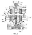
- the in-line nozzle 20e includes a nozzle channel 22e that has a diverted portion 150.
- the diverted portion 150 extends between a nozzle inlet 152 and a lower portion 154 of the nozzle channel 22e.
- a mold gate 24e of a mold cavity 26e is located adjacent the lower portion 154 of the nozzle channel 22e.
- the mold cavity 26e is delimited by a mold plate 28e and a mold core 30e. Cooling channels 158 are provided in the mold core 30e.
- a valve pin 160 extends through an upper portion 156 and the lower portion 154 of the nozzle channel 22e and is aligned with the mold gate 24e.
- a pair of piston 162 and cylinder 164 arrangements are disposed on either side of the nozzle 20e to actuate a valve pin/piston connector 166.
- the valve pin/piston connector 166 is coupled to the valve pin 160 to move the valve pin 160 axially within the nozzle channel 22e as indicated by arrow 170.
- a seal 168 is provided between the upper portion 156 and the lower portion 154 of the nozzle channel 22e to block melt from flowing into the upper portion 156.
- the seal 168 also serves as a guide to guide the axial movement of the valve pin 160.
- a heater assembly 80e surrounds the nozzle 20e.
- a threaded inner surface 88e of a heater sleeve 86e engages a threaded outer surface of the nozzle 20e.
- a spring 120e is disposed between a nozzle head 34e and the heater sleeve 86e.
- the heater sleeve 86e further includes an aperture 170 to allow the valve pin/piston connector 166 to pass therethrough.
- the valve pin/piston connector 166 is removed by sliding it axially out of engagement with the pistons 162. The heater assembly 80e is then threaded onto the nozzle 20e.
- a hot pressurized melt stream of moldable material is introduced into the nozzle inlet 152 from the machine nozzle 18e.
- the melt stream flows through the diverted portion 150 of the nozzle channel 22e and into the lower portion 154 of the nozzle 20e.
- the valve pin/piston connector 166 is movable as indicated by arrow 172 by the pistons 162 to axially move the valve pin 160.
- the flow of melt into the mold cavities 26e is selectively controlled by the valve pin 160 as it moves into and out of engagement with the mold gate 24e.
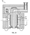
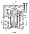
- FIG. 22 Another embodiment of a heater assembly 80f according to the present invention is shown in Figure 22 .
- the injection molding apparatus 10f is similar to the injection molding apparatus of Figure 2 and thus will not be described further.
- the heater assembly 80f is similar to the embodiment of Figure 3 , however, lock nut 108 has been replaced by nozzle tip nut 180.
- the nozzle tip nut 180 is screwed onto the nozzle 20f to abut the heater sleeve 86f Unlike the lock nut 108, the nozzle tip nut 180 can only travel a predetermined distance onto the nozzle 20f. This has the advantage that installation of the heater assembly 80f is simplified because it is clear to the operator when the nozzle tip nut 180 is in the fully installed position.
- the heater assembly 80g includes a heater sleeve 86g having an annular groove 182.
- the annular groove 182 provides an air gap 188 between the heater sleeve 86g and the nozzle 20g.
- the air gap 188 insulates the nozzle 20g along a predetermined length to profile the heat along the nozzle 20g. Heat is only directly transferred to the nozzle 20g where the heater sleeve 86g contacts the nozzle 20g. In this arrangement, the amount heat transferred to the nozzle 20g at various points along the nozzle body 36g can be controlled.
- any of the heater sleeves described previously may be provided with the annular groove 182. It will further be appreciated that the heater sleeve 86g may be used in any of the previously described heater assembly embodiments.
Landscapes
- Engineering & Computer Science (AREA)
- Manufacturing & Machinery (AREA)
- Mechanical Engineering (AREA)
- Moulds For Moulding Plastics Or The Like (AREA)
- Injection Moulding Of Plastics Or The Like (AREA)
Applications Claiming Priority (2)
| Application Number | Priority Date | Filing Date | Title |
|---|---|---|---|
| US210883 | 1994-03-18 | ||
| US10/210,883 US6780003B2 (en) | 2002-08-02 | 2002-08-02 | Removable heater for a hot runner nozzle |
Publications (2)
| Publication Number | Publication Date |
|---|---|
| EP1386717A1 EP1386717A1 (en) | 2004-02-04 |
| EP1386717B1 true EP1386717B1 (en) | 2008-03-12 |
Family
ID=30115245
Family Applications (1)
| Application Number | Title | Priority Date | Filing Date |
|---|---|---|---|
| EP03017780A Expired - Lifetime EP1386717B1 (en) | 2002-08-02 | 2003-08-04 | Threaded removable heater for a hot runner nozzle |
Country Status (6)
| Country | Link |
|---|---|
| US (2) | US6780003B2 (enExample) |
| EP (1) | EP1386717B1 (enExample) |
| JP (1) | JP4427286B2 (enExample) |
| CN (1) | CN100418728C (enExample) |
| CA (1) | CA2436571C (enExample) |
| DE (1) | DE60319637T2 (enExample) |
Families Citing this family (29)
| Publication number | Priority date | Publication date | Assignee | Title |
|---|---|---|---|---|
| US6394784B1 (en) * | 2000-03-08 | 2002-05-28 | Mold-Masters Limited | Compact cartridge hot runner nozzle |
| US6780003B2 (en) * | 2002-08-02 | 2004-08-24 | Mold-Masters Limited | Removable heater for a hot runner nozzle |
| US20050181090A1 (en) * | 2002-12-06 | 2005-08-18 | Mold-Masters Limited | Injection molding nozzle with embedded and removable heaters |
| US7118704B2 (en) * | 2002-12-13 | 2006-10-10 | Mold-Masters Limited | Nozzle and method for making a nozzle with a removable and replaceable heating device |
| WO2004113044A2 (en) * | 2003-06-20 | 2004-12-29 | Fast Heat, Inc. | Hot runner component heater having thermal sprayed resistive element |
| US7125242B2 (en) * | 2003-08-11 | 2006-10-24 | Mold-Masters Limited | Decompression device for an injection molding apparatus |
| US20050136146A1 (en) * | 2003-12-18 | 2005-06-23 | Phong Pham | Apparatus for automated method of injecting polymer to form a graphical design onto substrates |
| US20050245614A1 (en) * | 2004-03-04 | 2005-11-03 | Xanodyne Pharmaceuticals, Inc. | Tranexamic acid formulations |
| US7544056B2 (en) * | 2004-06-02 | 2009-06-09 | Mold-Masters (2007) Limited | Valve-gated injection molding nozzle having an annular flow |
| US7344372B2 (en) * | 2004-06-02 | 2008-03-18 | Mold-Masters (2007) Limited | Injection molding nozzle having an annular flow tip |
| CA2542374A1 (en) * | 2005-04-07 | 2006-10-07 | Mold-Masters Limited | Configurable manifold |
| US20070084850A1 (en) * | 2005-09-30 | 2007-04-19 | Husky Injection Molding Systems Ltd. | Electrical connector assembly for an arcuate surface in a high temperature environment and an associated method of use |
| US7714257B2 (en) * | 2005-09-30 | 2010-05-11 | Husky Injection Molding Systems Ltd. | Electrical connector assembly for an arcuate surface in a high temperature environment and an associated method of use |
| US7280750B2 (en) * | 2005-10-17 | 2007-10-09 | Watlow Electric Manufacturing Company | Hot runner nozzle heater and methods of manufacture thereof |
| US7462031B2 (en) * | 2005-11-25 | 2008-12-09 | Mold-Masters (2007) Limited | Injection molding nozzle with recessed terminal |
| US20070188562A1 (en) * | 2006-02-15 | 2007-08-16 | Mold-Masters Limited | Heater for a manifold of an injection molding apparatus |
| DE202006009056U1 (de) * | 2006-06-07 | 2006-08-10 | Günther Heisskanaltechnik Gmbh | Beheizte Spritzgießdüse |
| US20080187579A1 (en) * | 2007-02-01 | 2008-08-07 | Pavan Bhat | Extended-release dosage form |
| US7618253B2 (en) * | 2007-10-19 | 2009-11-17 | Mold-Masters (2007) Limited | Multiple-gate injection molding apparatus |
| US7914277B1 (en) * | 2009-03-31 | 2011-03-29 | Honda Motor Co., Ltd. | Heater housing and heater for plastic injection machine nozzle |
| CN102791460B (zh) * | 2009-12-29 | 2015-05-27 | 圣万提注塑工业有限公司 | 流体流道加热装置 |
| BE1022045B1 (nl) * | 2011-02-03 | 2016-02-09 | Resilux | Spuitgietinrichting voor het vervaardigen van holle voorwerpen, i.h.b. kunststofvoorvormelingen, resp.-behouders, en werkwijze hiervoor |
| DE102012101400B4 (de) * | 2012-02-22 | 2013-10-31 | Günther Heisskanaltechnik Gmbh | Heißkanaldüse mit einem elektrischen Heizelement |
| CN103507202A (zh) * | 2012-06-20 | 2014-01-15 | 天津市岱曼得科技发展有限公司 | 超大型塑料注射成型设备及工艺 |
| CN204222111U (zh) * | 2013-09-10 | 2015-03-25 | 奥托门纳创新有限责任公司 | 具有分区段式加热器的热流道喷嘴 |
| KR101718912B1 (ko) * | 2015-05-07 | 2017-03-22 | 주식회사 유도 | 사출성형용 노즐 |
| KR101781370B1 (ko) * | 2015-11-27 | 2017-09-25 | 주식회사 와이드 | 사출성형기용 노즐 조립체 |
| CN111413003B (zh) * | 2020-03-23 | 2021-04-27 | 天津大学 | 一种音速喷嘴管壁热场分布测量系统 |
| WO2025173037A2 (en) * | 2024-02-14 | 2025-08-21 | Vasantha Tool Crafts Private Limited | A hot runner injection molding system |
Family Cites Families (33)
| Publication number | Priority date | Publication date | Assignee | Title |
|---|---|---|---|---|
| US124215A (en) * | 1872-03-05 | Improvement in adjustable horseshoes | ||
| GB1359539A (en) | 1971-10-18 | 1974-07-10 | Pyrotenax Ltd | Electric heating device |
| DE7603206U1 (de) | 1976-02-05 | 1976-06-10 | Belz, Wolfgang, 6081 Dornheim | Regelbarer heisslaeuferblock mit 8 seitlichen angussduesen zum spritzen von kleinteilen aus thermoplastischem kunststoff ohne anguss |
| US4268241A (en) | 1978-01-06 | 1981-05-19 | Husky Injection Molding Systems | Heated injection nozzle |
| GB2044162B (en) | 1978-12-14 | 1982-10-13 | Gellert Jobst U | Sprue bushing for an injection moulding apparatus |
| DE3100092C2 (de) | 1981-01-03 | 1983-01-27 | Türk & Hillinger GmbH & Co, 7200 Tuttlingen | Elektrischer Heizkörper insbesondere für Kunststoff-Spritzdüsen |
| CA1177214A (en) | 1982-03-31 | 1984-11-06 | Jobst U. Gellert | Pressure casting process |
| DE3568525D1 (en) * | 1984-05-31 | 1989-04-06 | Toyota Motor Co Ltd | Device for tightening a coil on a cylindrical body |
| JPH01217883A (ja) | 1988-02-25 | 1989-08-31 | Jiyuuou:Kk | 誘導加熱コイル用ボビン |
| NL9000488A (nl) | 1990-03-01 | 1991-10-01 | Eurotool Bv | Werkwijze voor het vervaardigen van een inspuitmondstuk voor toepassing bij een spuitgiet-inrichting. |
| US5136141A (en) | 1990-10-31 | 1992-08-04 | Melt Design, Inc. | Integral sprue bushing assembly |
| CN2106706U (zh) * | 1991-11-16 | 1992-06-10 | 常州第二电子仪器厂 | 注塑机阀门式无浇道喷嘴 |
| US5360333A (en) | 1992-09-30 | 1994-11-01 | Husky Injection Molding Systems Ltd. | Band heater clamp arrangement for an injection molding machine |
| US5411392A (en) | 1993-11-15 | 1995-05-02 | Husky Injection Molding Systems Ltd. | Heated nozzle assembly including a heater clamp arrangement |
| JP2792435B2 (ja) * | 1994-06-01 | 1998-09-03 | 株式会社新潟鉄工所 | 射出成形機のノズル装置 |
| CA2127211C (en) * | 1994-06-30 | 2004-09-21 | Jobst Ulrich Gellert | Injection molding nozzle with removable collar portion |
| US5533882A (en) | 1994-11-29 | 1996-07-09 | Husky Injection Molding Systems Ltd. | Hot runner valve gated system |
| DE29501450U1 (de) | 1995-01-31 | 1995-03-30 | Dipl.-Ing. Herbert Günther Gesellschaft mbH, Perchtoldsdorf | Heißkanaldüse |
| DE19601102C2 (de) | 1996-01-13 | 1999-04-15 | Psg Plastic Service Gmbh | Heißkanalsystem |
| DE69619362T2 (de) | 1996-05-10 | 2002-07-11 | EUROTOOL BEHEER B.V., GROVENDEEL/'S-GRAVENDEEL | Spritzgiesssystem und Erhitzungsaufbau zur Verwendung in einem derartigen System |
| US5879727A (en) * | 1997-01-21 | 1999-03-09 | Husky Injection Molding Systems, Ltd. | Insulated modular injection nozzle system |
| US6309207B1 (en) | 1998-06-10 | 2001-10-30 | Husky Injection Molding Systems Ltd. | Injection molding nozzle assembly |
| DE29800473U1 (de) * | 1998-01-13 | 1998-03-19 | Mold-Masters Limited, Georgetown, Ontario | Außenbeheizte Heißkanaldüse mit Heizdraht |
| US6043466A (en) | 1998-02-20 | 2000-03-28 | Husky Injection Molding Systems Ltd. | Hot runner heating clamp |
| US6163016A (en) | 1998-10-20 | 2000-12-19 | Thermetic Products, Inc. | Heater clamp |
| US6164954A (en) | 1998-12-08 | 2000-12-26 | Husky Injection Molding Systems Ltd. | High pressure injection nozzle |
| US6220851B1 (en) | 1999-04-19 | 2001-04-24 | Husky Injection Molding Systems Ltd. | Detachable nozzle body |
| DE50007658D1 (de) * | 1999-05-06 | 2004-10-14 | Hotset Heizpatronen Zubehoer | Rohrartiges Heizelement |
| DE19950273C1 (de) | 1999-10-18 | 2001-03-15 | Otto Maenner Heiskanalsysteme | Heißkanaldüse |
| US6343925B1 (en) | 2000-04-14 | 2002-02-05 | Husky Injection Molding Systems, Ltd. | Hot runner valve gate piston assembly |
| EP1314531A1 (en) | 2001-11-22 | 2003-05-28 | Synventive Molding Solutions B.V. | Helical heating element for an injection moulding device |
| US6780003B2 (en) * | 2002-08-02 | 2004-08-24 | Mold-Masters Limited | Removable heater for a hot runner nozzle |
| US6609902B1 (en) * | 2002-11-12 | 2003-08-26 | Husky Injection Molding Systems Ltd. | Injection molding nozzle |
-
2002
- 2002-08-02 US US10/210,883 patent/US6780003B2/en not_active Expired - Lifetime
-
2003
- 2003-08-01 CA CA2436571A patent/CA2436571C/en not_active Expired - Fee Related
- 2003-08-04 DE DE60319637T patent/DE60319637T2/de not_active Expired - Lifetime
- 2003-08-04 EP EP03017780A patent/EP1386717B1/en not_active Expired - Lifetime
- 2003-08-04 CN CNB031580904A patent/CN100418728C/zh not_active Expired - Fee Related
- 2003-08-04 JP JP2003286290A patent/JP4427286B2/ja not_active Expired - Fee Related
-
2004
- 2004-07-07 US US10/885,128 patent/US7125243B2/en not_active Expired - Lifetime
Also Published As
| Publication number | Publication date |
|---|---|
| DE60319637T2 (de) | 2008-07-17 |
| US20040258793A1 (en) | 2004-12-23 |
| JP4427286B2 (ja) | 2010-03-03 |
| EP1386717A1 (en) | 2004-02-04 |
| JP2004130783A (ja) | 2004-04-30 |
| CN100418728C (zh) | 2008-09-17 |
| CN1500611A (zh) | 2004-06-02 |
| US7125243B2 (en) | 2006-10-24 |
| DE60319637D1 (de) | 2008-04-24 |
| CA2436571C (en) | 2011-05-03 |
| CA2436571A1 (en) | 2004-02-02 |
| US20040022891A1 (en) | 2004-02-05 |
| US6780003B2 (en) | 2004-08-24 |
Similar Documents
| Publication | Publication Date | Title |
|---|---|---|
| EP1386717B1 (en) | Threaded removable heater for a hot runner nozzle | |
| EP0590621B1 (en) | Band heater clamp arrangement | |
| US6043466A (en) | Hot runner heating clamp | |
| KR100867026B1 (ko) | 가열 러너 노즐 및 다중 노즐 배열체 | |
| US4238671A (en) | Sprue bushing with cast in heater element | |
| US4576567A (en) | Injection molding system having an insulation sleeve | |
| EP2174767B1 (en) | Injection molding valve gated hot runner nozzle | |
| US6220851B1 (en) | Detachable nozzle body | |
| CN101421090A (zh) | 用于注射成型设备的歧管的板式加热器 | |
| US9987782B2 (en) | Hot runner nozzle with a segmented heater | |
| KR100548865B1 (ko) | 착탈식 노즐 본체 및 방법 | |
| US20040137107A1 (en) | Hot runner nozzle with a tip, a tip surrounding piece and an alignment piece | |
| US7131833B2 (en) | Nozzle with thermally conductive device | |
| JP2006514885A (ja) | スプルー装置 | |
| EP1951495B1 (en) | Injection molding component with low profile terminal connection | |
| EP0496284A2 (en) | Injection molding apparatus with integral cooling in a forward portion of the nozzle | |
| US7118704B2 (en) | Nozzle and method for making a nozzle with a removable and replaceable heating device | |
| WO2025173037A2 (en) | A hot runner injection molding system |
Legal Events
| Date | Code | Title | Description |
|---|---|---|---|
| PUAI | Public reference made under article 153(3) epc to a published international application that has entered the european phase |
Free format text: ORIGINAL CODE: 0009012 |
|
| AK | Designated contracting states |
Kind code of ref document: A1 Designated state(s): AT BE BG CH CY CZ DE DK EE ES FI FR GB GR HU IE IT LI LU MC NL PT RO SE SI SK TR |
|
| AX | Request for extension of the european patent |
Extension state: AL LT LV MK |
|
| 17P | Request for examination filed |
Effective date: 20040802 |
|
| 17Q | First examination report despatched |
Effective date: 20040831 |
|
| AKX | Designation fees paid |
Designated state(s): DE FR GB IT |
|
| GRAP | Despatch of communication of intention to grant a patent |
Free format text: ORIGINAL CODE: EPIDOSNIGR1 |
|
| GRAS | Grant fee paid |
Free format text: ORIGINAL CODE: EPIDOSNIGR3 |
|
| GRAA | (expected) grant |
Free format text: ORIGINAL CODE: 0009210 |
|
| RAP1 | Party data changed (applicant data changed or rights of an application transferred) |
Owner name: MOLD-MASTERS (2007) LIMITED |
|
| AK | Designated contracting states |
Kind code of ref document: B1 Designated state(s): DE FR GB IT |
|
| REG | Reference to a national code |
Ref country code: GB Ref legal event code: FG4D |
|
| REF | Corresponds to: |
Ref document number: 60319637 Country of ref document: DE Date of ref document: 20080424 Kind code of ref document: P |
|
| ET | Fr: translation filed | ||
| PLBE | No opposition filed within time limit |
Free format text: ORIGINAL CODE: 0009261 |
|
| STAA | Information on the status of an ep patent application or granted ep patent |
Free format text: STATUS: NO OPPOSITION FILED WITHIN TIME LIMIT |
|
| 26N | No opposition filed |
Effective date: 20081215 |
|
| REG | Reference to a national code |
Ref country code: FR Ref legal event code: PLFP Year of fee payment: 14 |
|
| REG | Reference to a national code |
Ref country code: FR Ref legal event code: PLFP Year of fee payment: 15 |
|
| REG | Reference to a national code |
Ref country code: FR Ref legal event code: PLFP Year of fee payment: 16 |
|
| PGFP | Annual fee paid to national office [announced via postgrant information from national office to epo] |
Ref country code: DE Payment date: 20180719 Year of fee payment: 16 Ref country code: IT Payment date: 20180719 Year of fee payment: 16 Ref country code: FR Payment date: 20180720 Year of fee payment: 16 |
|
| PGFP | Annual fee paid to national office [announced via postgrant information from national office to epo] |
Ref country code: GB Payment date: 20180720 Year of fee payment: 16 |
|
| REG | Reference to a national code |
Ref country code: DE Ref legal event code: R119 Ref document number: 60319637 Country of ref document: DE |
|
| GBPC | Gb: european patent ceased through non-payment of renewal fee |
Effective date: 20190804 |
|
| PG25 | Lapsed in a contracting state [announced via postgrant information from national office to epo] |
Ref country code: FR Free format text: LAPSE BECAUSE OF NON-PAYMENT OF DUE FEES Effective date: 20190831 Ref country code: DE Free format text: LAPSE BECAUSE OF NON-PAYMENT OF DUE FEES Effective date: 20200303 |
|
| PG25 | Lapsed in a contracting state [announced via postgrant information from national office to epo] |
Ref country code: IT Free format text: LAPSE BECAUSE OF NON-PAYMENT OF DUE FEES Effective date: 20190804 Ref country code: GB Free format text: LAPSE BECAUSE OF NON-PAYMENT OF DUE FEES Effective date: 20190804 |