EP1385177A1 - Système de conduits pour un réseau de véhicule - Google Patents
Système de conduits pour un réseau de véhicule Download PDFInfo
- Publication number
- EP1385177A1 EP1385177A1 EP03016367A EP03016367A EP1385177A1 EP 1385177 A1 EP1385177 A1 EP 1385177A1 EP 03016367 A EP03016367 A EP 03016367A EP 03016367 A EP03016367 A EP 03016367A EP 1385177 A1 EP1385177 A1 EP 1385177A1
- Authority
- EP
- European Patent Office
- Prior art keywords
- detector
- line
- arrangement according
- electrical
- carrier
- Prior art date
- Legal status (The legal status is an assumption and is not a legal conclusion. Google has not performed a legal analysis and makes no representation as to the accuracy of the status listed.)
- Granted
Links
Images


Classifications
-
- B—PERFORMING OPERATIONS; TRANSPORTING
- B60—VEHICLES IN GENERAL
- B60R—VEHICLES, VEHICLE FITTINGS, OR VEHICLE PARTS, NOT OTHERWISE PROVIDED FOR
- B60R16/00—Electric or fluid circuits specially adapted for vehicles and not otherwise provided for; Arrangement of elements of electric or fluid circuits specially adapted for vehicles and not otherwise provided for
- B60R16/02—Electric or fluid circuits specially adapted for vehicles and not otherwise provided for; Arrangement of elements of electric or fluid circuits specially adapted for vehicles and not otherwise provided for electric constitutive elements
-
- H—ELECTRICITY
- H01—ELECTRIC ELEMENTS
- H01B—CABLES; CONDUCTORS; INSULATORS; SELECTION OF MATERIALS FOR THEIR CONDUCTIVE, INSULATING OR DIELECTRIC PROPERTIES
- H01B7/00—Insulated conductors or cables characterised by their form
- H01B7/32—Insulated conductors or cables characterised by their form with arrangements for indicating defects, e.g. breaks or leaks
- H01B7/324—Insulated conductors or cables characterised by their form with arrangements for indicating defects, e.g. breaks or leaks comprising temperature sensing means
-
- H—ELECTRICITY
- H02—GENERATION; CONVERSION OR DISTRIBUTION OF ELECTRIC POWER
- H02G—INSTALLATION OF ELECTRIC CABLES OR LINES, OR OF COMBINED OPTICAL AND ELECTRIC CABLES OR LINES
- H02G3/00—Installations of electric cables or lines or protective tubing therefor in or on buildings, equivalent structures or vehicles
- H02G3/02—Details
- H02G3/04—Protective tubing or conduits, e.g. cable ladders or cable troughs
- H02G3/0462—Tubings, i.e. having a closed section
- H02G3/0481—Tubings, i.e. having a closed section with a circular cross-section
-
- H—ELECTRICITY
- H02—GENERATION; CONVERSION OR DISTRIBUTION OF ELECTRIC POWER
- H02H—EMERGENCY PROTECTIVE CIRCUIT ARRANGEMENTS
- H02H5/00—Emergency protective circuit arrangements for automatic disconnection directly responsive to an undesired change from normal non-electric working conditions with or without subsequent reconnection
- H02H5/04—Emergency protective circuit arrangements for automatic disconnection directly responsive to an undesired change from normal non-electric working conditions with or without subsequent reconnection responsive to abnormal temperature
- H02H5/042—Emergency protective circuit arrangements for automatic disconnection directly responsive to an undesired change from normal non-electric working conditions with or without subsequent reconnection responsive to abnormal temperature using temperature dependent resistors
- H02H5/043—Emergency protective circuit arrangements for automatic disconnection directly responsive to an undesired change from normal non-electric working conditions with or without subsequent reconnection responsive to abnormal temperature using temperature dependent resistors the temperature dependent resistor being disposed parallel to a heating wire, e.g. in a heating blanket
Definitions
- the invention relates to a line arrangement for vehicle electrical systems of vehicles, comprising one of a power feed terminal to a power output terminal extending electrical supply line with at least one current-carrying inner conductor and at least one surrounding this Protective jacket.
- Is the electrical supply line operated with voltages exceeding 12 volts, preferably over 20 volts, are, so there is a latent risk potential when the inner conductor has a defect or when the Protective jacket takes damage, since then beyond the defect of the inner conductor away or, starting from the inner conductor to any part of the Vehicle, in particular to a part of the vehicle lying on the ground, each can form an arc, which is a significant fire hazard represents.
- the invention is therefore based on the object, a line arrangement of generic type to improve such that when forming an arc can be quickly remedied.
- the advantage of the solution according to the invention is the fact that this is the Possibility creates, immediately after the occurrence of a current-carrying Inner conductor outgoing arc to recognize this and thereby remedy to provide that the current-carrying inner conductor separated from the power source so that the arc goes out immediately and no further damage from can go out the arc.
- the arrangement also provides a mechanical protection direct contact between the spatially encased internal supply line with a voltage greater than 20 volts and others spatially Potentials outside the line arrangement.
- the probability a short circuit between the spatially internal supply line and the spatially external potentials is thus greatly reduced. For example, outside systems with lower voltage can thereby before the effects of a potential increase by the supply line to be protected.
- the detector element at local thermal action its electrical and / or optical behavior irreversibly worsened.
- the detector element can be special train easily and expediently.
- the detector element can then be particularly simple and expedient form, if this local thermal exposure its Ability to pass electrical and / or optical signals irreversibly degraded.
- the detector element in each case a forming Arc detected, it is preferably provided that the detector element surrounds the supply line.
- the detector element it would be conceivable for the detector element to consist of a flat piece of material form, whose electrical and / or optical properties be changed when an arc occurs.
- the detector element at least one electrical and / or optical line as a detector line whose electrical and / or optical behavior at the occurrence of the Arc is irreversibly changed.
- An advantageous embodiment of the detector line according to the invention provides that the detector line runs in the form of a helix.
- Another alternative solution for this provides that the detector line in Meandering form of meanders, the meander then preferably in a the supply line at least partially, even better substantially enclosing Area lie.
- the detector line In addition to the execution of the detector line as a helix or meander are but also other possibilities conceivable. For example, it would be conceivable To perform the detector line in the form of a network or a tissue.
- the supply line consecutive and transverse to a longitudinal direction the supply line extending portions of the detector line have a distance from each other which is smaller than twice the diameter of the inner conductor.
- Detector lead made of a material, which is its electrical and / or optical behavior due to arcing Radiation changes.
- the detector line is made of a material which is an electrical and / or optical behavior at a local Entry of an amount of heat generated by the arc irreversibly changed.
- the heat generated by the arc cause for is the irreversible change of electrical and / or optical behavior.
- the detector line is made of a material that is an electrical and / or optical behavior already from a threshold temperature, which is in the range of about 100 ° C to about 500 ° C, irreversibly changed.
- the detector line is preferably provided that this surrounded by an insulating protective cover.
- the detector element has a carrier on or in which the detector line is held.
- detector line in the form of Conductor paths is arranged on a support.
- the detector line on the Carrier is applied in the form of a printing or coating process, and thus, the integrity of the carrier is necessary to maintain the integrity of the detector line To be upright.
- the detector line is preferably a vapor-deposited Metallization or an applied conductive, for example powdery Material or an applied optical signals conductive material.
- the carrier may be formed, for example, as a tubular casing, which encloses the supply line, or as for example in cross section C-shaped element enclosing the supply line.
- Another advantageous solution provides to form the carrier as a carrier strip, which helically surrounds the supply line.
- the carrier at least partially the supply line surrounds.
- each carrier strip partially surrounds the supply line, the sum of all carrier strips completely encloses the supply line.
- the carrier, the supply line in essentially completely encloses.
- the Carrier forms part of a protective cover for the detector line.
- the carrier can consist of a variety of materials.
- the carrier is a possible against thermal or other effects resistant material.
- the carrier can also be used to change the contribute electrical and / or optical behavior of the detector element.
- an advantageous embodiment provides that the carrier of a Material is that in case of local exposure of emanating from the inner conductor Arc irreversibly changed.
- the changes can be arbitrary, for example, the Material be chosen so that the carrier at least a part of its mechanical Properties changed.
- the carrier is made of a material is that when exposed to the emanating from the inner conductor arc irreversibly deformed.
- a further advantageous embodiment of an on the formation of an arc Reactive carrier provides that the carrier of a material is that under the action of emanating from the inner conductor arc irreversibly disintegrates.
- a further advantageous solution provides that the carrier due to its irreversible change in local action of the electric arc and / or optical behavior of the detector line irreversibly impaired.
- this can be mechanical in an optical detector line Voltages which are the optical behavior of an optical conductor influence.
- the detector element is its electrical and / or optical behavior when the arc occurs irreversibly changed.
- the Detector element In order to avoid mechanical damage to the piping via the same Detecting detector element is preferably provided that the Detector element its electrical and / or optical behavior in mechanical Damage irreversibly changed.
- a particularly advantageous embodiment provides that the detector element its electrical and / or optical behavior in mechanical Damage of the same by a detector on the outside of the potential changed mechanical component changed.
- the detector element is provided with a detector line
- the detector line their electrical and / or optical behavior with mechanical damage to the detector element changed irreversibly.
- the detector line is in a detector line specific circuit, so that a contact of the detector line with a on a detektor effetsfremden Potential lying mechanical component can be detected, because it disturbs the detector line specific circuit.
- At least one detector circuit is provided, which drives the isolation circuit.
- the detector circuit preferably operates so that they are the electrical and / or optical behavior of the detector element, in particular the detector line same, constantly checked and in case of irreversible change this behavior controls the separation circuit such that this is the supply line disconnects from the power source.
- the detector circuit can in principle be anywhere on the Be provided for as long as a communication with the Isolating circuit is ensured.
- the at least one detector circuit the current output terminal assigned.
- a further advantageous solution provides that a plurality of detector circuits are provided, which communicate with each other.
- multiple detector circuits is it possible to have a conduit arrangement not just at one but to check in several places.
- the detector circuits can be used in a variety of ways and Way communicate with each other and also with the isolation circuit.
- the at least one detector circuit communicates with the disconnecting circuit by means of an electric line.
- An alternative solution provides that the at least one detector circuit communicates with the disconnecting circuit by means of a light guide.
- each of the plurality of circuits in communication with the separation circuit is and the isolation circuit a signal to disconnect the supply line from the power source can give. That means that in this Case each of the detector circuits operates independently of the other.
- the detector circuits do not work independently, but in a kind Network and that each of the detector circuits is not independent of the other detector circuit, the electrical and / or optical behavior of the Detector element checks, but the review by communication at least two detector circuits takes place.
- such a communication can take place in that a Detector circuit sends a signal which the other detector circuit receives.
- the other Detect detector circuit whether the detector element with respect to its electrical and / or optical behavior has changed.
- the detector element can either be directly connected to the isolation circuit interact with or with the detector circuit which has sent out the signal and, for example, to this detector circuit again send back a confirmation signal or no acknowledgment signal, so that the first transmitting detector circuit then due to this feedback communicates with the disconnecting circuit.
- the communication of the detector circuits can be different Way be realized.
- This line internal line can either be a separate, in the wiring harness provided line for communication of the detector circuits be with each other or it may directly the detector element, in particular the detector line thereof are used to the detector circuits let communicate with each other.
- the detector circuits via a line outside the line communicate with each other.
- Such a line extraneous line may be an additional separate Be line, such a line external line can also be a usual electrical or optical data bus, as they are in anyway modern motor vehicles is present.
- the detector circuits can thereby either via an electrical Line communicate with each other or via an optical line.
- the detector circuits in one direction an electrical line, namely in another direction via an optical Communicate with each other.
- an optical line and an electrical line in the form of a Provide detector line in the wiring harness, so that the two detector lines not only enable the communication of the detector circuits, but at the same time by communication over these detector lines too It is possible to check to what extent their electrical and / or optical behavior changes.
- the detector circuit detects the occurrence of a detector-line-external potential recognizes in the detector line and after detecting the same Disconnecting circuit controls so that it is the supply line of the Power source disconnects.
- a first embodiment of a conduit arrangement according to the invention in particular for vehicle electrical systems of vehicles, preferably of motor vehicles, includes a designated as a whole with 10 wiring harness with a from a power feed terminal 12 to a power output terminal 14 extending electrical supply line 16, which at least one current-carrying inner conductor 18 and at least one this inner conductor 18th surrounding protective jacket 20 includes.
- the power supply terminal 12 is designated as a whole by 22 Isolating circuit connected between a power source 24 and the power feed terminal 12 is provided and is capable of the supply line 16 quickly de-energized.
- the current source 24 operates at a voltage of more than 40 volts, for example, about 42 volts DC, so that the inner conductor 18 of the supply line 16 is at this voltage, if one with the current output terminal 14 connected consumer 26, for example a Vehicle unit, to be operated via the supply line 16.
- FIG. 1 A second error case is shown in FIG. In this case, the inner conductor 18 Broken.
- a current flows through the damaged inner conductor 18 forms At this point, a local, so-called serial arc 28 'from, the from a fracture end of the inner conductor 18 to the opposite end of the fracture of the inner conductor 18 leads, if the broken ends still in the immediate Be close or touch it loosely.
- Such an arc 28 or 28 ', in particular at voltages of greater than 20 volts can very quickly become a fire of fire Protective jacket 20 of the supply line 16 or damage to other parts lead the vehicle.
- the line arrangement 10 comprises a detector element 32, which is essentially from the power feed terminal 12 to the power output terminal 14 extends and also encloses the supply line 16.
- the detector element 32 is designed so that it occurs when a Arc 28 or 28 ', the detector element 32 in a region 34th interspersed or spread within it, in this area 34 locally its electrical and / or optical conductivity changed.
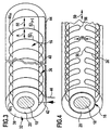
- the detector element 32 for this purpose as shown in Fig. 3, a detector line 36, which together with the supply line 16 in a Protective cover 38 is embedded and helical with successive Windings 40, the supply line 16 over its extension from the Stromeinspeiseanschluß 12 surrounds the current output terminal 14.
- These two connecting pieces 42 and 44 are, as shown in Fig. 1, preferably connected to a detector circuit 48, which occur at the Arc 28 is capable of separating circuit 22 via an electrical or optical line 49 to control such that this connection between the power feed terminal 12 and the power source 24 interrupts.
- the detector line 36 is laid so that transverse to a longitudinal direction 50 of the supply line 16 consecutive sections 52 I and 52 I + 1 of Detector line 36 have a distance A from each other, which is smaller than the extent of a usually adjusting arc 28 or 28 ', preferably smaller than approximately the diameter of the inner conductor 18th
- the detector line 36 is formed of a material which during the Occurrence of the arc 28 or 28 'its electrical or optical behavior changed irreversibly.
- the detector line 36 is designed, for example, as an electrically conductive line, so provides a way to make this electrical line in the form of a Metal wire to perform, wherein such a metal wire of metals of the Group of eutectics, which also includes materials such as solder is.
- a metal wire of metals of the Group of eutectics which also includes materials such as solder is.
- Eutektika can be the temperature from which a irreversible thermal destruction of the pipe at a certain point, for example, by melting takes place, by the material composition adjust the same in a simple manner.
- an electrical use conductive plastic or polymer fiber as detector line 36 which when forming an arc 28 or 28 'within the area 34 irreversibly thermally degraded and thus also at least their electrical Conductivity changes, in particular reduced.
- the detector circuit 48 is on by applying a voltage the fittings 42 and 46 capable of the electrical behavior of the Detector line 36 and changes, in particular deterioration, of electrical conductivity, which is an indication of the occurrence of an arc 28 or 28 'are. In these cases causes the detector circuit 48, the isolation circuit 22 to the power supply terminal 12 to be separated from the power source 24.
- the detector line 36 as an optical line, in particular as Execute light guide.
- such a light guide is a polymer light guide, which consists of a polymer is produced whose optical transmission is exceeded a temperature threshold, for example, from a temperature in Range from about 100 ° C to about 500 ° C, significantly worsened.
- a temperature threshold for example, from a temperature in Range from about 100 ° C to about 500 ° C, significantly worsened.
- the detector circuit 48 is thus capable of being fed by injecting light in one of the fittings 42 or 46 and detection of light at each other connector 46 and 42, the optical transmission of the detector line 36 record and register changes that are indicative of the Forming an arc 28 or 28 'are.
- the Detector circuit 48 by suitably driving the separation circuit 22 a Disconnecting the power feed terminal 12 from the power source 24th
- the detector element insensitive to water, microbiologically resistant, Flame retardant, lightfast, vibration resistant and resistant to Reagents and cleaning agents, in particular gasoline, diesel, battery acid, Brake fluid, preservative, detergent or oil, each at highest operating temperature, is.
- the detector line 36' does not run around the supply line 16 but in the form of a supply line 16 in the longitudinal direction 50 of the supply line 16 and azimuthally in the supply line 16 substantially enclosing meanders 54 which - as shown in Figure 4 in processing -. juxtaposed in the longitudinal direction 50, wherein the transverse to the longitudinal direction 50 consecutive sections 52 I and 52 I + 1 also have a distance a from each other, is smaller than the Expansion of the usually adjusting arc 28, preferably less than approximately the diameter of the inner conductor 18th
- bend pieces 56 of the meander 54 in the azimuthal direction Supply line 16 also a distance B from each other, which is smaller as the extent of the usually adjusting arc 28, in particular less than approximately the diameter of the inner conductor 18.
- Such a detector line designed in the form of successive meanders 54 36 ', as shown in FIG. 5, can preferably be produced by that on a support 58, the detector line 36 'forming tracks 60th be applied, for example in the form of electrically conductive webs either of a metal, in particular of a metal from the group of Eutectic, or of an electrically conductive plastic or polymer.
- Such application of the webs 60 on the carrier 58 can by known masking or sputtering techniques upon propagation of the support 58 in FIG a surface so that the carrier after application of the webs 60 to the at least one supply line 16 can be wound around.
- the detector line 36 may basically be designed as an electrical line or as an optical line, wherein in any case, their behavior when the arc occurs 28 irreversible Changes in order to detect these by means of the detector circuit 48 can.
- a fourth embodiment which is based on the principle of the third Embodiment is based, to form the detector line 36 'the Webs 60 applied to a carrier strip 59 and in the same way as in the third embodiment by a cover layer 62 in the width of Carrier strip 59 covered.
- two carrier strips 59 1 and 59 2 are now wound over the protective jacket 20 of the inner conductor 18 in an opposite direction, and embedded in the protective envelope 38 together with the supply line 16 in the same way as in the first exemplary embodiment.
- the detector lines 36 'of the carrier strips 59 1 and 59 2 are in each case connected to one of the connecting pieces 42 and 44 on the side of the power supply terminal 12 and in the region of the current output terminal 14, the detector lines 36' are directly connected to each other, so that on the carrier strip 59 1 and 59 2 provided detector lines 36 'are connected in series between the connecting pieces 42 and 44 and also the return line 44 can be omitted, since one of the detector lines 36' itself forms the return line.
- detector lines 36 ' can be on the one hand optimal coverage of the supply line 16 and on the other hand achieve optimal manufacturability of a wiring harness 10 according to the invention.
- the detector lines 36 be both electrical and optical lines.
- the carrier 58 made of a strongly deforming when the arc 28 within the region 34, for example, contracting material, which results in that sections 64 k to 64 k + 3 of the detector line 36, which are subject to the change in shape of the carrier 58 within the region 34, are subjected to such great mechanical stresses that the detector line 36 greatly changes their electrical or optical behavior in these sections 64; in an extreme case, this breaks in particular the electrical or optical behavior of the detector line 36 'irreversibly changed.
- a detector circuit 48 ' E or 48' A is assigned to both the current supply terminal 12 and the current output terminal 14 of the supply line 16 as an alternative to the simplest and most cost-effective embodiments with only one detector circuit 48 wherein the detector circuits 48 ' E and 48' A communicate with each other.
- the detector circuit 48 ' E sends a detector signal S1 through the detector element 32 from the power supply terminal 12 to the power output terminal 14, which receives the detector circuit 48' A and then generates a detector signal S2 is sent via the detector element 32 so that it is received by the detector circuit 48 ' E.
- the detector circuit 48 ' A does not receive the detector signal S1 in the intended quality or not at all and in turn generates no detector signal S2, so that the detector circuit 48' E receives no detector signal S2 and from this detects the occurrence of the arc 28 and thus causes the separation circuit 22, the power supply terminal 12 to be separated from the power source 24.
- the emitted signals S1 and S2 can be electrical or optical Be detector signals, so that the signal S1 transmitting the detector line 36 of the detector element 32 represent an electrical or an optical line can and independently of the signal S2 transmitting return 44, which may also be another detector line 36, such as in the fourth embodiment, also an electrical or optical line
- an additional line 66 extending externally from the wiring harness 10 is provided, via which the detector circuit 48 ' A sends back the detector signal S2 to the detector circuit 48' E.
- This additional line 66 may be an additional in the line arrangement be provided line, but also a separate running from this Line, for example, an electrical or optical data bus, anyway is present in a vehicle.
- two detector elements 32 1 and 32 2 are provided in the wiring harness 10, wherein for example via the detector element 32 1, the detector signal S1 from the detector circuit 48 ' E to the detector circuit 48' A is sent while the detector signal S2 is sent via the detector element 32 2 from the detector circuit 48 ' A to the detector circuit 48' E.
- the detector elements 32 1 and 32 2 each comprise only a portion of the supply line 16 in the azimuthal direction and complement each other so far that the supply line 16 is completely detected in Azimutalcardi, such as in the fourth embodiment, or the detector elements 32 1 and 32 2 form a total redundant system, and both enclose the supply line 16 substantially completely.
- both detector elements 32 1 and 32 2 it is possible to design both detector elements 32 1 and 32 2 to have a detector line 36 which is either an electrical line or an optical line in both.
- the detector line 36 of the one detector element for example, the detector element 32 1
- the detector element 32 1 to perform as an optical line and the detector line 36 of the detector element 32 2 as an electrical line, so that the detector elements 32 1 and 32 2 can be formed so that the occurrence of the arc 28 in at least one of them leads to a change of the electrical behavior and in the other of which to a change of the optical behavior.
- the detector circuit 48 in addition to the previous described embodiments, the detector circuit 48 "modified in such a way that these are not just a change in the electrical and / or recognizes optical ability to transmit detector signals, but also in addition a change in an electrical potential of the detector element 32.
- the detector circuit 48 "designed so that they not only the electrical Conductivity of the detector element 32 checks, but also the Potential with respect to ground, the detector circuit 48 "recognizes the Damage to the detector element 32 and thus also the separation circuit 22 cause the power supply terminal 12 from the power source 24 to separate.
- Such a potential detection can be realized in a tenth embodiment, as shown in Fig. 16, even if both the power supply terminal 12 and the power output terminal 14 each have a detector circuit 48 "is assigned, namely the detector circuit 48" E and the detector circuit 48 " a. recognizing both detector circuits 48 "e and 48" a, a change in potential of the respective detector element 32 1 or 32 2 as can also mechanical damage, for example triggered by the at ground body part 68, detected and due to this the power feeding terminal 12 of the Current source 24 are separated by the separation circuit 22.
- the combination of optically operating and electrically operating detector elements 32 can be realized in this solution, so that, for example, the detector element 32 1 responds to an arc by changing the optical behavior, while the detector element 32 2 responds to an arc by changing its electrical behavior , At the same time, the detector circuits 48 "still detect when the detector element 32 2 changes its electrical potential due to the action of the body part 68.
- the detector elements 32 and regardless of how they work, it is always possible to coarse mechanical effects on the wiring harness 10, in particular the Detector elements 32, thereby determining that these mechanical effects in any case also to a damage of the detector line 36th and thus to change their electrical and / or optical behavior leads.
Applications Claiming Priority (2)
| Application Number | Priority Date | Filing Date | Title |
|---|---|---|---|
| DE10234389 | 2002-07-23 | ||
| DE10234389A DE10234389A1 (de) | 2002-07-23 | 2002-07-23 | Leitungsanordnung für Bordnetze von Fahrzeugen |
Publications (2)
| Publication Number | Publication Date |
|---|---|
| EP1385177A1 true EP1385177A1 (fr) | 2004-01-28 |
| EP1385177B1 EP1385177B1 (fr) | 2013-07-03 |
Family
ID=29796607
Family Applications (1)
| Application Number | Title | Priority Date | Filing Date |
|---|---|---|---|
| EP03016367.9A Expired - Lifetime EP1385177B1 (fr) | 2002-07-23 | 2003-07-19 | Système de conduits pour un réseau de véhicule |
Country Status (4)
| Country | Link |
|---|---|
| US (1) | US20040252429A1 (fr) |
| EP (1) | EP1385177B1 (fr) |
| DE (1) | DE10234389A1 (fr) |
| ES (1) | ES2428624T3 (fr) |
Cited By (2)
| Publication number | Priority date | Publication date | Assignee | Title |
|---|---|---|---|---|
| US10734136B2 (en) | 2017-07-20 | 2020-08-04 | Leoni Kabel Gmbh | Cable with sheath arrangement for detecting bending |
| CN116500048A (zh) * | 2023-06-28 | 2023-07-28 | 四川联畅信通科技有限公司 | 一种线缆卡具缺陷检测方法、装置、设备及介质 |
Families Citing this family (4)
| Publication number | Priority date | Publication date | Assignee | Title |
|---|---|---|---|---|
| JP4595482B2 (ja) * | 2004-10-08 | 2010-12-08 | トヨタ自動車株式会社 | 車両用電源装置 |
| DE102014018642B4 (de) | 2014-12-13 | 2021-07-08 | Audi Ag | EMV-Maßnahme und Kurzschlussdetektion im Kraftfahrzeug |
| JP6448583B2 (ja) * | 2016-06-29 | 2019-01-09 | 矢崎総業株式会社 | ワイヤハーネス |
| DE102018126406B4 (de) * | 2018-10-23 | 2020-12-31 | Peter Herges | Vorrichtung zur Lichtbogenerkennung in einem Gleichstromkreis eines Kraftfahrzeugs und Verwendung zur Überwachung einer Batterieanordnung |
Citations (5)
| Publication number | Priority date | Publication date | Assignee | Title |
|---|---|---|---|---|
| JPH07141920A (ja) * | 1993-11-22 | 1995-06-02 | Sumitomo Wiring Syst Ltd | ワイヤハーネス |
| US5541803A (en) * | 1994-03-07 | 1996-07-30 | Pope, Jr.; Ralph E. | Electrical safety device |
| EP0728622A2 (fr) * | 1995-02-21 | 1996-08-28 | Hitachi, Ltd. | Appareil pour le multiplexage entre unités dans un véhicule |
| DE10017455A1 (de) * | 2000-04-07 | 2001-10-18 | Audi Ag | Schutzvorrichtung für ein Stromkabel in einem Kraftfahrzeug |
| WO2003007450A1 (fr) * | 2001-07-10 | 2003-01-23 | Daimlerchrysler Ag | Procede et dispositif de protection d'un conducteur lors de l'apparition d'un arc electrique |
Family Cites Families (7)
| Publication number | Priority date | Publication date | Assignee | Title |
|---|---|---|---|---|
| US3588689A (en) * | 1969-06-16 | 1971-06-28 | Harry F Crawford | Variable impedance system for electrical cable fault locating and temperature monitoring |
| DE7127047U (de) * | 1971-07-14 | 1971-09-30 | Felten & Guilleaume Kabelwerke Ag | Elektrische temperaturueberwachungsmessleitung mit zwei leitern fuer starkstrom- und hochspannungskabel |
| US3956726A (en) * | 1974-12-23 | 1976-05-11 | Cerro Corporation | Heat detecting conductor and circuit |
| US5801914A (en) * | 1996-05-23 | 1998-09-01 | Sunbeam Products, Inc. | Electrical safety circuit with a breakable conductive element |
| US6265880B1 (en) * | 1999-06-15 | 2001-07-24 | The United States Of America As Represented By The Secretary Of The Air Force | Apparatus and method for detecting conduit chafing |
| DE19935439A1 (de) * | 1999-07-28 | 2001-02-15 | Siemens Ag | Sensorleitung |
| DE10000551C1 (de) * | 2000-01-08 | 2001-07-05 | Bayerische Motoren Werke Ag | Vorrichtung zur Überwachung einer Batterieleitung |
-
2002
- 2002-07-23 DE DE10234389A patent/DE10234389A1/de not_active Ceased
-
2003
- 2003-07-19 EP EP03016367.9A patent/EP1385177B1/fr not_active Expired - Lifetime
- 2003-07-19 ES ES03016367T patent/ES2428624T3/es not_active Expired - Lifetime
- 2003-07-21 US US10/626,834 patent/US20040252429A1/en not_active Abandoned
Patent Citations (5)
| Publication number | Priority date | Publication date | Assignee | Title |
|---|---|---|---|---|
| JPH07141920A (ja) * | 1993-11-22 | 1995-06-02 | Sumitomo Wiring Syst Ltd | ワイヤハーネス |
| US5541803A (en) * | 1994-03-07 | 1996-07-30 | Pope, Jr.; Ralph E. | Electrical safety device |
| EP0728622A2 (fr) * | 1995-02-21 | 1996-08-28 | Hitachi, Ltd. | Appareil pour le multiplexage entre unités dans un véhicule |
| DE10017455A1 (de) * | 2000-04-07 | 2001-10-18 | Audi Ag | Schutzvorrichtung für ein Stromkabel in einem Kraftfahrzeug |
| WO2003007450A1 (fr) * | 2001-07-10 | 2003-01-23 | Daimlerchrysler Ag | Procede et dispositif de protection d'un conducteur lors de l'apparition d'un arc electrique |
Cited By (3)
| Publication number | Priority date | Publication date | Assignee | Title |
|---|---|---|---|---|
| US10734136B2 (en) | 2017-07-20 | 2020-08-04 | Leoni Kabel Gmbh | Cable with sheath arrangement for detecting bending |
| CN116500048A (zh) * | 2023-06-28 | 2023-07-28 | 四川联畅信通科技有限公司 | 一种线缆卡具缺陷检测方法、装置、设备及介质 |
| CN116500048B (zh) * | 2023-06-28 | 2023-09-15 | 四川联畅信通科技有限公司 | 一种线缆卡具缺陷检测方法、装置、设备及介质 |
Also Published As
| Publication number | Publication date |
|---|---|
| ES2428624T3 (es) | 2013-11-08 |
| US20040252429A1 (en) | 2004-12-16 |
| DE10234389A1 (de) | 2004-02-05 |
| EP1385177B1 (fr) | 2013-07-03 |
Similar Documents
| Publication | Publication Date | Title |
|---|---|---|
| EP3218230B1 (fr) | Réseau d'alimentation de vehicule automobile | |
| EP0620565A2 (fr) | Câble coaxial à haute fréquence | |
| DE112016003124B4 (de) | Abschirmstruktur und abschirmendes geflochtenes Element | |
| DE112008003375T5 (de) | Wasserabdichtverfahren für einen Draht und Draht, welcher ein wasserdichtes Teil aufweist, welches durch das Wasserabdichtverfahren gebildet ist | |
| WO2018060152A1 (fr) | Câble électrique équipé d'une conduite de réfrigérant | |
| EP0209826A2 (fr) | Câble | |
| DE102008063086A1 (de) | Erdungskabel, insbesondere Bahnerdungskabel zur Erdung von Eisenbahneinrichtungen | |
| WO2007045345A1 (fr) | Cable a trois conducteurs | |
| WO2014057017A1 (fr) | Réseau filaire, notamment réseau de bord à tension continue destiné à un véhicule à moteur, ainsi que procédé de surveillance d'un réseau de bord en ce qui concerne la survenue d'un arc électrique | |
| DE10132752B4 (de) | Verfahren und Vorrichtung zum Schutz eines Leiters bei Auftreten eines Lichtbogens | |
| EP1662288A1 (fr) | Dispositif de protection pour fibre guide de lumière | |
| DE19747557B4 (de) | Hochstrom-Sicherungseinheit | |
| EP1385177B1 (fr) | Système de conduits pour un réseau de véhicule | |
| EP0321661B1 (fr) | Dispositif de surveillance d'un élément de construction soumis à l'usure | |
| WO2004002202A1 (fr) | Plaquette pour boitiers de commande electroniques pour vehicules | |
| EP2737326B1 (fr) | Circuit de conduction d'un courant électrique | |
| EP3080872B1 (fr) | Liaison de contact de lignes de données blindées à une carte de circuits et procédé de mise en contact d'une pluralité de lignes de données blindées avec une carte de circuits | |
| DE202005018553U1 (de) | Schutzeinrichtung für Lichtleitfasern | |
| DE102006027498B4 (de) | Mechanisches Schutzschlauchsystem für elektrische Leitungen, insbesondere in Kraftfahrzeugen | |
| DE212017000099U1 (de) | Eine Bimetall-Endhülse | |
| EP3369099B1 (fr) | Ligne électrique | |
| EP1637908B1 (fr) | Câble pour lumière laser avec des fils conducteurs électriques bobinés | |
| DE102011001889A1 (de) | Solarpaneelanschlussleitung | |
| EP2581916A1 (fr) | Câble d'allumage pour charges mécaniques et/ou thermiques élevées | |
| DE102019216285B4 (de) | Flachkabel und Batteriemodul |
Legal Events
| Date | Code | Title | Description |
|---|---|---|---|
| PUAI | Public reference made under article 153(3) epc to a published international application that has entered the european phase |
Free format text: ORIGINAL CODE: 0009012 |
|
| AK | Designated contracting states |
Kind code of ref document: A1 Designated state(s): AT BE BG CH CY CZ DE DK EE ES FI FR GB GR HU IE IT LI LU MC NL PT RO SE SI SK TR |
|
| AX | Request for extension of the european patent |
Extension state: AL LT LV MK |
|
| 17P | Request for examination filed |
Effective date: 20040124 |
|
| AKX | Designation fees paid |
Designated state(s): AT BE BG CH CY CZ DE DK EE ES FI FR GB GR HU IE IT LI LU MC NL PT RO SE SI SK TR |
|
| 17Q | First examination report despatched |
Effective date: 20090507 |
|
| RAP1 | Party data changed (applicant data changed or rights of an application transferred) |
Owner name: AFL EUROPE GMBH |
|
| RAP1 | Party data changed (applicant data changed or rights of an application transferred) |
Owner name: SUMITOMO ELECTRIC BORDNETZE GMBH |
|
| REG | Reference to a national code |
Ref country code: DE Ref legal event code: R079 Ref document number: 50314822 Country of ref document: DE Free format text: PREVIOUS MAIN CLASS: H01B0007320000 Ipc: H02G0003040000 |
|
| GRAP | Despatch of communication of intention to grant a patent |
Free format text: ORIGINAL CODE: EPIDOSNIGR1 |
|
| RIC1 | Information provided on ipc code assigned before grant |
Ipc: H01B 7/32 20060101ALI20130103BHEP Ipc: B60R 16/02 20060101ALI20130103BHEP Ipc: H02G 3/04 20060101AFI20130103BHEP Ipc: H02H 5/04 20060101ALI20130103BHEP |
|
| GRAS | Grant fee paid |
Free format text: ORIGINAL CODE: EPIDOSNIGR3 |
|
| GRAA | (expected) grant |
Free format text: ORIGINAL CODE: 0009210 |
|
| AK | Designated contracting states |
Kind code of ref document: B1 Designated state(s): AT BE BG CH CY CZ DE DK EE ES FI FR GB GR HU IE IT LI LU MC NL PT RO SE SI SK TR |
|
| REG | Reference to a national code |
Ref country code: GB Ref legal event code: FG4D Free format text: NOT ENGLISH |
|
| REG | Reference to a national code |
Ref country code: CH Ref legal event code: EP Ref country code: AT Ref legal event code: REF Ref document number: 620219 Country of ref document: AT Kind code of ref document: T Effective date: 20130715 |
|
| REG | Reference to a national code |
Ref country code: IE Ref legal event code: FG4D Free format text: LANGUAGE OF EP DOCUMENT: GERMAN |
|
| REG | Reference to a national code |
Ref country code: DE Ref legal event code: R096 Ref document number: 50314822 Country of ref document: DE Effective date: 20130829 |
|
| REG | Reference to a national code |
Ref country code: SE Ref legal event code: TRGR |
|
| PG25 | Lapsed in a contracting state [announced via postgrant information from national office to epo] |
Ref country code: SI Free format text: LAPSE BECAUSE OF FAILURE TO SUBMIT A TRANSLATION OF THE DESCRIPTION OR TO PAY THE FEE WITHIN THE PRESCRIBED TIME-LIMIT Effective date: 20130703 |
|
| REG | Reference to a national code |
Ref country code: ES Ref legal event code: FG2A Ref document number: 2428624 Country of ref document: ES Kind code of ref document: T3 Effective date: 20131108 |
|
| REG | Reference to a national code |
Ref country code: NL Ref legal event code: VDEP Effective date: 20130703 |
|
| BERE | Be: lapsed |
Owner name: SUMITOMO ELECTRIC BORDNETZE G.M.B.H. Effective date: 20130731 |
|
| PG25 | Lapsed in a contracting state [announced via postgrant information from national office to epo] |
Ref country code: PT Free format text: LAPSE BECAUSE OF FAILURE TO SUBMIT A TRANSLATION OF THE DESCRIPTION OR TO PAY THE FEE WITHIN THE PRESCRIBED TIME-LIMIT Effective date: 20131104 Ref country code: CY Free format text: LAPSE BECAUSE OF FAILURE TO SUBMIT A TRANSLATION OF THE DESCRIPTION OR TO PAY THE FEE WITHIN THE PRESCRIBED TIME-LIMIT Effective date: 20130619 |
|
| PG25 | Lapsed in a contracting state [announced via postgrant information from national office to epo] |
Ref country code: FI Free format text: LAPSE BECAUSE OF FAILURE TO SUBMIT A TRANSLATION OF THE DESCRIPTION OR TO PAY THE FEE WITHIN THE PRESCRIBED TIME-LIMIT Effective date: 20130703 Ref country code: NL Free format text: LAPSE BECAUSE OF FAILURE TO SUBMIT A TRANSLATION OF THE DESCRIPTION OR TO PAY THE FEE WITHIN THE PRESCRIBED TIME-LIMIT Effective date: 20130703 Ref country code: GR Free format text: LAPSE BECAUSE OF FAILURE TO SUBMIT A TRANSLATION OF THE DESCRIPTION OR TO PAY THE FEE WITHIN THE PRESCRIBED TIME-LIMIT Effective date: 20131004 |
|
| REG | Reference to a national code |
Ref country code: CH Ref legal event code: PL |
|
| PG25 | Lapsed in a contracting state [announced via postgrant information from national office to epo] |
Ref country code: CY Free format text: LAPSE BECAUSE OF FAILURE TO SUBMIT A TRANSLATION OF THE DESCRIPTION OR TO PAY THE FEE WITHIN THE PRESCRIBED TIME-LIMIT Effective date: 20130703 |
|
| REG | Reference to a national code |
Ref country code: IE Ref legal event code: MM4A |
|
| PG25 | Lapsed in a contracting state [announced via postgrant information from national office to epo] |
Ref country code: CH Free format text: LAPSE BECAUSE OF NON-PAYMENT OF DUE FEES Effective date: 20130731 Ref country code: LI Free format text: LAPSE BECAUSE OF NON-PAYMENT OF DUE FEES Effective date: 20130731 Ref country code: EE Free format text: LAPSE BECAUSE OF FAILURE TO SUBMIT A TRANSLATION OF THE DESCRIPTION OR TO PAY THE FEE WITHIN THE PRESCRIBED TIME-LIMIT Effective date: 20130703 Ref country code: BE Free format text: LAPSE BECAUSE OF NON-PAYMENT OF DUE FEES Effective date: 20130731 Ref country code: MC Free format text: LAPSE BECAUSE OF FAILURE TO SUBMIT A TRANSLATION OF THE DESCRIPTION OR TO PAY THE FEE WITHIN THE PRESCRIBED TIME-LIMIT Effective date: 20130703 Ref country code: CZ Free format text: LAPSE BECAUSE OF FAILURE TO SUBMIT A TRANSLATION OF THE DESCRIPTION OR TO PAY THE FEE WITHIN THE PRESCRIBED TIME-LIMIT Effective date: 20130703 Ref country code: SK Free format text: LAPSE BECAUSE OF FAILURE TO SUBMIT A TRANSLATION OF THE DESCRIPTION OR TO PAY THE FEE WITHIN THE PRESCRIBED TIME-LIMIT Effective date: 20130703 Ref country code: RO Free format text: LAPSE BECAUSE OF FAILURE TO SUBMIT A TRANSLATION OF THE DESCRIPTION OR TO PAY THE FEE WITHIN THE PRESCRIBED TIME-LIMIT Effective date: 20130703 Ref country code: DK Free format text: LAPSE BECAUSE OF FAILURE TO SUBMIT A TRANSLATION OF THE DESCRIPTION OR TO PAY THE FEE WITHIN THE PRESCRIBED TIME-LIMIT Effective date: 20130703 |
|
| PLBE | No opposition filed within time limit |
Free format text: ORIGINAL CODE: 0009261 |
|
| STAA | Information on the status of an ep patent application or granted ep patent |
Free format text: STATUS: NO OPPOSITION FILED WITHIN TIME LIMIT |
|
| 26N | No opposition filed |
Effective date: 20140404 |
|
| REG | Reference to a national code |
Ref country code: DE Ref legal event code: R097 Ref document number: 50314822 Country of ref document: DE Effective date: 20140404 |
|
| PG25 | Lapsed in a contracting state [announced via postgrant information from national office to epo] |
Ref country code: IE Free format text: LAPSE BECAUSE OF NON-PAYMENT OF DUE FEES Effective date: 20130719 |
|
| REG | Reference to a national code |
Ref country code: AT Ref legal event code: MM01 Ref document number: 620219 Country of ref document: AT Kind code of ref document: T Effective date: 20130719 |
|
| PG25 | Lapsed in a contracting state [announced via postgrant information from national office to epo] |
Ref country code: AT Free format text: LAPSE BECAUSE OF NON-PAYMENT OF DUE FEES Effective date: 20130719 |
|
| PG25 | Lapsed in a contracting state [announced via postgrant information from national office to epo] |
Ref country code: TR Free format text: LAPSE BECAUSE OF FAILURE TO SUBMIT A TRANSLATION OF THE DESCRIPTION OR TO PAY THE FEE WITHIN THE PRESCRIBED TIME-LIMIT Effective date: 20130703 |
|
| REG | Reference to a national code |
Ref country code: FR Ref legal event code: PLFP Year of fee payment: 13 |
|
| PG25 | Lapsed in a contracting state [announced via postgrant information from national office to epo] |
Ref country code: BG Free format text: LAPSE BECAUSE OF FAILURE TO SUBMIT A TRANSLATION OF THE DESCRIPTION OR TO PAY THE FEE WITHIN THE PRESCRIBED TIME-LIMIT Effective date: 20130703 Ref country code: LU Free format text: LAPSE BECAUSE OF NON-PAYMENT OF DUE FEES Effective date: 20130719 Ref country code: HU Free format text: LAPSE BECAUSE OF FAILURE TO SUBMIT A TRANSLATION OF THE DESCRIPTION OR TO PAY THE FEE WITHIN THE PRESCRIBED TIME-LIMIT; INVALID AB INITIO Effective date: 20030719 |
|
| REG | Reference to a national code |
Ref country code: FR Ref legal event code: PLFP Year of fee payment: 14 |
|
| REG | Reference to a national code |
Ref country code: FR Ref legal event code: PLFP Year of fee payment: 15 |
|
| PGFP | Annual fee paid to national office [announced via postgrant information from national office to epo] |
Ref country code: FR Payment date: 20170720 Year of fee payment: 15 Ref country code: GB Payment date: 20170724 Year of fee payment: 15 Ref country code: IT Payment date: 20170721 Year of fee payment: 15 Ref country code: ES Payment date: 20170818 Year of fee payment: 15 |
|
| PGFP | Annual fee paid to national office [announced via postgrant information from national office to epo] |
Ref country code: SE Payment date: 20170724 Year of fee payment: 15 |
|
| GBPC | Gb: european patent ceased through non-payment of renewal fee |
Effective date: 20180719 |
|
| PG25 | Lapsed in a contracting state [announced via postgrant information from national office to epo] |
Ref country code: GB Free format text: LAPSE BECAUSE OF NON-PAYMENT OF DUE FEES Effective date: 20180719 Ref country code: FR Free format text: LAPSE BECAUSE OF NON-PAYMENT OF DUE FEES Effective date: 20180731 |
|
| PG25 | Lapsed in a contracting state [announced via postgrant information from national office to epo] |
Ref country code: SE Free format text: LAPSE BECAUSE OF NON-PAYMENT OF DUE FEES Effective date: 20180720 |
|
| PG25 | Lapsed in a contracting state [announced via postgrant information from national office to epo] |
Ref country code: IT Free format text: LAPSE BECAUSE OF NON-PAYMENT OF DUE FEES Effective date: 20180719 |
|
| REG | Reference to a national code |
Ref country code: ES Ref legal event code: FD2A Effective date: 20190917 |
|
| PG25 | Lapsed in a contracting state [announced via postgrant information from national office to epo] |
Ref country code: ES Free format text: LAPSE BECAUSE OF NON-PAYMENT OF DUE FEES Effective date: 20180720 |
|
| PGFP | Annual fee paid to national office [announced via postgrant information from national office to epo] |
Ref country code: DE Payment date: 20210726 Year of fee payment: 19 |
|
| REG | Reference to a national code |
Ref country code: DE Ref legal event code: R119 Ref document number: 50314822 Country of ref document: DE |
|
| PG25 | Lapsed in a contracting state [announced via postgrant information from national office to epo] |
Ref country code: DE Free format text: LAPSE BECAUSE OF NON-PAYMENT OF DUE FEES Effective date: 20230201 |