EP1385177A1 - Circuit arrangement for electrical network on board a vehicle - Google Patents
Circuit arrangement for electrical network on board a vehicle Download PDFInfo
- Publication number
- EP1385177A1 EP1385177A1 EP03016367A EP03016367A EP1385177A1 EP 1385177 A1 EP1385177 A1 EP 1385177A1 EP 03016367 A EP03016367 A EP 03016367A EP 03016367 A EP03016367 A EP 03016367A EP 1385177 A1 EP1385177 A1 EP 1385177A1
- Authority
- EP
- European Patent Office
- Prior art keywords
- detector
- line
- arrangement according
- electrical
- carrier
- Prior art date
- Legal status (The legal status is an assumption and is not a legal conclusion. Google has not performed a legal analysis and makes no representation as to the accuracy of the status listed.)
- Granted
Links
Images


Classifications
-
- B—PERFORMING OPERATIONS; TRANSPORTING
- B60—VEHICLES IN GENERAL
- B60R—VEHICLES, VEHICLE FITTINGS, OR VEHICLE PARTS, NOT OTHERWISE PROVIDED FOR
- B60R16/00—Electric or fluid circuits specially adapted for vehicles and not otherwise provided for; Arrangement of elements of electric or fluid circuits specially adapted for vehicles and not otherwise provided for
- B60R16/02—Electric or fluid circuits specially adapted for vehicles and not otherwise provided for; Arrangement of elements of electric or fluid circuits specially adapted for vehicles and not otherwise provided for electric constitutive elements
-
- H—ELECTRICITY
- H01—ELECTRIC ELEMENTS
- H01B—CABLES; CONDUCTORS; INSULATORS; SELECTION OF MATERIALS FOR THEIR CONDUCTIVE, INSULATING OR DIELECTRIC PROPERTIES
- H01B7/00—Insulated conductors or cables characterised by their form
- H01B7/32—Insulated conductors or cables characterised by their form with arrangements for indicating defects, e.g. breaks or leaks
- H01B7/324—Insulated conductors or cables characterised by their form with arrangements for indicating defects, e.g. breaks or leaks comprising temperature sensing means
-
- H—ELECTRICITY
- H02—GENERATION; CONVERSION OR DISTRIBUTION OF ELECTRIC POWER
- H02G—INSTALLATION OF ELECTRIC CABLES OR LINES, OR OF COMBINED OPTICAL AND ELECTRIC CABLES OR LINES
- H02G3/00—Installations of electric cables or lines or protective tubing therefor in or on buildings, equivalent structures or vehicles
- H02G3/02—Details
- H02G3/04—Protective tubing or conduits, e.g. cable ladders or cable troughs
- H02G3/0462—Tubings, i.e. having a closed section
- H02G3/0481—Tubings, i.e. having a closed section with a circular cross-section
-
- H—ELECTRICITY
- H02—GENERATION; CONVERSION OR DISTRIBUTION OF ELECTRIC POWER
- H02H—EMERGENCY PROTECTIVE CIRCUIT ARRANGEMENTS
- H02H5/00—Emergency protective circuit arrangements for automatic disconnection directly responsive to an undesired change from normal non-electric working conditions with or without subsequent reconnection
- H02H5/04—Emergency protective circuit arrangements for automatic disconnection directly responsive to an undesired change from normal non-electric working conditions with or without subsequent reconnection responsive to abnormal temperature
- H02H5/042—Emergency protective circuit arrangements for automatic disconnection directly responsive to an undesired change from normal non-electric working conditions with or without subsequent reconnection responsive to abnormal temperature using temperature dependent resistors
- H02H5/043—Emergency protective circuit arrangements for automatic disconnection directly responsive to an undesired change from normal non-electric working conditions with or without subsequent reconnection responsive to abnormal temperature using temperature dependent resistors the temperature dependent resistor being disposed parallel to a heating wire, e.g. in a heating blanket
Definitions
- the invention relates to a line arrangement for vehicle electrical systems of vehicles, comprising one of a power feed terminal to a power output terminal extending electrical supply line with at least one current-carrying inner conductor and at least one surrounding this Protective jacket.
- Is the electrical supply line operated with voltages exceeding 12 volts, preferably over 20 volts, are, so there is a latent risk potential when the inner conductor has a defect or when the Protective jacket takes damage, since then beyond the defect of the inner conductor away or, starting from the inner conductor to any part of the Vehicle, in particular to a part of the vehicle lying on the ground, each can form an arc, which is a significant fire hazard represents.
- the invention is therefore based on the object, a line arrangement of generic type to improve such that when forming an arc can be quickly remedied.
- the advantage of the solution according to the invention is the fact that this is the Possibility creates, immediately after the occurrence of a current-carrying Inner conductor outgoing arc to recognize this and thereby remedy to provide that the current-carrying inner conductor separated from the power source so that the arc goes out immediately and no further damage from can go out the arc.
- the arrangement also provides a mechanical protection direct contact between the spatially encased internal supply line with a voltage greater than 20 volts and others spatially Potentials outside the line arrangement.
- the probability a short circuit between the spatially internal supply line and the spatially external potentials is thus greatly reduced. For example, outside systems with lower voltage can thereby before the effects of a potential increase by the supply line to be protected.
- the detector element at local thermal action its electrical and / or optical behavior irreversibly worsened.
- the detector element can be special train easily and expediently.
- the detector element can then be particularly simple and expedient form, if this local thermal exposure its Ability to pass electrical and / or optical signals irreversibly degraded.
- the detector element in each case a forming Arc detected, it is preferably provided that the detector element surrounds the supply line.
- the detector element it would be conceivable for the detector element to consist of a flat piece of material form, whose electrical and / or optical properties be changed when an arc occurs.
- the detector element at least one electrical and / or optical line as a detector line whose electrical and / or optical behavior at the occurrence of the Arc is irreversibly changed.
- An advantageous embodiment of the detector line according to the invention provides that the detector line runs in the form of a helix.
- Another alternative solution for this provides that the detector line in Meandering form of meanders, the meander then preferably in a the supply line at least partially, even better substantially enclosing Area lie.
- the detector line In addition to the execution of the detector line as a helix or meander are but also other possibilities conceivable. For example, it would be conceivable To perform the detector line in the form of a network or a tissue.
- the supply line consecutive and transverse to a longitudinal direction the supply line extending portions of the detector line have a distance from each other which is smaller than twice the diameter of the inner conductor.
- Detector lead made of a material, which is its electrical and / or optical behavior due to arcing Radiation changes.
- the detector line is made of a material which is an electrical and / or optical behavior at a local Entry of an amount of heat generated by the arc irreversibly changed.
- the heat generated by the arc cause for is the irreversible change of electrical and / or optical behavior.
- the detector line is made of a material that is an electrical and / or optical behavior already from a threshold temperature, which is in the range of about 100 ° C to about 500 ° C, irreversibly changed.
- the detector line is preferably provided that this surrounded by an insulating protective cover.
- the detector element has a carrier on or in which the detector line is held.
- detector line in the form of Conductor paths is arranged on a support.
- the detector line on the Carrier is applied in the form of a printing or coating process, and thus, the integrity of the carrier is necessary to maintain the integrity of the detector line To be upright.
- the detector line is preferably a vapor-deposited Metallization or an applied conductive, for example powdery Material or an applied optical signals conductive material.
- the carrier may be formed, for example, as a tubular casing, which encloses the supply line, or as for example in cross section C-shaped element enclosing the supply line.
- Another advantageous solution provides to form the carrier as a carrier strip, which helically surrounds the supply line.
- the carrier at least partially the supply line surrounds.
- each carrier strip partially surrounds the supply line, the sum of all carrier strips completely encloses the supply line.
- the carrier, the supply line in essentially completely encloses.
- the Carrier forms part of a protective cover for the detector line.
- the carrier can consist of a variety of materials.
- the carrier is a possible against thermal or other effects resistant material.
- the carrier can also be used to change the contribute electrical and / or optical behavior of the detector element.
- an advantageous embodiment provides that the carrier of a Material is that in case of local exposure of emanating from the inner conductor Arc irreversibly changed.
- the changes can be arbitrary, for example, the Material be chosen so that the carrier at least a part of its mechanical Properties changed.
- the carrier is made of a material is that when exposed to the emanating from the inner conductor arc irreversibly deformed.
- a further advantageous embodiment of an on the formation of an arc Reactive carrier provides that the carrier of a material is that under the action of emanating from the inner conductor arc irreversibly disintegrates.
- a further advantageous solution provides that the carrier due to its irreversible change in local action of the electric arc and / or optical behavior of the detector line irreversibly impaired.
- this can be mechanical in an optical detector line Voltages which are the optical behavior of an optical conductor influence.
- the detector element is its electrical and / or optical behavior when the arc occurs irreversibly changed.
- the Detector element In order to avoid mechanical damage to the piping via the same Detecting detector element is preferably provided that the Detector element its electrical and / or optical behavior in mechanical Damage irreversibly changed.
- a particularly advantageous embodiment provides that the detector element its electrical and / or optical behavior in mechanical Damage of the same by a detector on the outside of the potential changed mechanical component changed.
- the detector element is provided with a detector line
- the detector line their electrical and / or optical behavior with mechanical damage to the detector element changed irreversibly.
- the detector line is in a detector line specific circuit, so that a contact of the detector line with a on a detektor effetsfremden Potential lying mechanical component can be detected, because it disturbs the detector line specific circuit.
- At least one detector circuit is provided, which drives the isolation circuit.
- the detector circuit preferably operates so that they are the electrical and / or optical behavior of the detector element, in particular the detector line same, constantly checked and in case of irreversible change this behavior controls the separation circuit such that this is the supply line disconnects from the power source.
- the detector circuit can in principle be anywhere on the Be provided for as long as a communication with the Isolating circuit is ensured.
- the at least one detector circuit the current output terminal assigned.
- a further advantageous solution provides that a plurality of detector circuits are provided, which communicate with each other.
- multiple detector circuits is it possible to have a conduit arrangement not just at one but to check in several places.
- the detector circuits can be used in a variety of ways and Way communicate with each other and also with the isolation circuit.
- the at least one detector circuit communicates with the disconnecting circuit by means of an electric line.
- An alternative solution provides that the at least one detector circuit communicates with the disconnecting circuit by means of a light guide.
- each of the plurality of circuits in communication with the separation circuit is and the isolation circuit a signal to disconnect the supply line from the power source can give. That means that in this Case each of the detector circuits operates independently of the other.
- the detector circuits do not work independently, but in a kind Network and that each of the detector circuits is not independent of the other detector circuit, the electrical and / or optical behavior of the Detector element checks, but the review by communication at least two detector circuits takes place.
- such a communication can take place in that a Detector circuit sends a signal which the other detector circuit receives.
- the other Detect detector circuit whether the detector element with respect to its electrical and / or optical behavior has changed.
- the detector element can either be directly connected to the isolation circuit interact with or with the detector circuit which has sent out the signal and, for example, to this detector circuit again send back a confirmation signal or no acknowledgment signal, so that the first transmitting detector circuit then due to this feedback communicates with the disconnecting circuit.
- the communication of the detector circuits can be different Way be realized.
- This line internal line can either be a separate, in the wiring harness provided line for communication of the detector circuits be with each other or it may directly the detector element, in particular the detector line thereof are used to the detector circuits let communicate with each other.
- the detector circuits via a line outside the line communicate with each other.
- Such a line extraneous line may be an additional separate Be line, such a line external line can also be a usual electrical or optical data bus, as they are in anyway modern motor vehicles is present.
- the detector circuits can thereby either via an electrical Line communicate with each other or via an optical line.
- the detector circuits in one direction an electrical line, namely in another direction via an optical Communicate with each other.
- an optical line and an electrical line in the form of a Provide detector line in the wiring harness, so that the two detector lines not only enable the communication of the detector circuits, but at the same time by communication over these detector lines too It is possible to check to what extent their electrical and / or optical behavior changes.
- the detector circuit detects the occurrence of a detector-line-external potential recognizes in the detector line and after detecting the same Disconnecting circuit controls so that it is the supply line of the Power source disconnects.
- a first embodiment of a conduit arrangement according to the invention in particular for vehicle electrical systems of vehicles, preferably of motor vehicles, includes a designated as a whole with 10 wiring harness with a from a power feed terminal 12 to a power output terminal 14 extending electrical supply line 16, which at least one current-carrying inner conductor 18 and at least one this inner conductor 18th surrounding protective jacket 20 includes.
- the power supply terminal 12 is designated as a whole by 22 Isolating circuit connected between a power source 24 and the power feed terminal 12 is provided and is capable of the supply line 16 quickly de-energized.
- the current source 24 operates at a voltage of more than 40 volts, for example, about 42 volts DC, so that the inner conductor 18 of the supply line 16 is at this voltage, if one with the current output terminal 14 connected consumer 26, for example a Vehicle unit, to be operated via the supply line 16.
- FIG. 1 A second error case is shown in FIG. In this case, the inner conductor 18 Broken.
- a current flows through the damaged inner conductor 18 forms At this point, a local, so-called serial arc 28 'from, the from a fracture end of the inner conductor 18 to the opposite end of the fracture of the inner conductor 18 leads, if the broken ends still in the immediate Be close or touch it loosely.
- Such an arc 28 or 28 ', in particular at voltages of greater than 20 volts can very quickly become a fire of fire Protective jacket 20 of the supply line 16 or damage to other parts lead the vehicle.
- the line arrangement 10 comprises a detector element 32, which is essentially from the power feed terminal 12 to the power output terminal 14 extends and also encloses the supply line 16.
- the detector element 32 is designed so that it occurs when a Arc 28 or 28 ', the detector element 32 in a region 34th interspersed or spread within it, in this area 34 locally its electrical and / or optical conductivity changed.
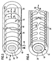
- the detector element 32 for this purpose as shown in Fig. 3, a detector line 36, which together with the supply line 16 in a Protective cover 38 is embedded and helical with successive Windings 40, the supply line 16 over its extension from the Stromeinspeiseanschluß 12 surrounds the current output terminal 14.
- These two connecting pieces 42 and 44 are, as shown in Fig. 1, preferably connected to a detector circuit 48, which occur at the Arc 28 is capable of separating circuit 22 via an electrical or optical line 49 to control such that this connection between the power feed terminal 12 and the power source 24 interrupts.
- the detector line 36 is laid so that transverse to a longitudinal direction 50 of the supply line 16 consecutive sections 52 I and 52 I + 1 of Detector line 36 have a distance A from each other, which is smaller than the extent of a usually adjusting arc 28 or 28 ', preferably smaller than approximately the diameter of the inner conductor 18th
- the detector line 36 is formed of a material which during the Occurrence of the arc 28 or 28 'its electrical or optical behavior changed irreversibly.
- the detector line 36 is designed, for example, as an electrically conductive line, so provides a way to make this electrical line in the form of a Metal wire to perform, wherein such a metal wire of metals of the Group of eutectics, which also includes materials such as solder is.
- a metal wire of metals of the Group of eutectics which also includes materials such as solder is.
- Eutektika can be the temperature from which a irreversible thermal destruction of the pipe at a certain point, for example, by melting takes place, by the material composition adjust the same in a simple manner.
- an electrical use conductive plastic or polymer fiber as detector line 36 which when forming an arc 28 or 28 'within the area 34 irreversibly thermally degraded and thus also at least their electrical Conductivity changes, in particular reduced.
- the detector circuit 48 is on by applying a voltage the fittings 42 and 46 capable of the electrical behavior of the Detector line 36 and changes, in particular deterioration, of electrical conductivity, which is an indication of the occurrence of an arc 28 or 28 'are. In these cases causes the detector circuit 48, the isolation circuit 22 to the power supply terminal 12 to be separated from the power source 24.
- the detector line 36 as an optical line, in particular as Execute light guide.
- such a light guide is a polymer light guide, which consists of a polymer is produced whose optical transmission is exceeded a temperature threshold, for example, from a temperature in Range from about 100 ° C to about 500 ° C, significantly worsened.
- a temperature threshold for example, from a temperature in Range from about 100 ° C to about 500 ° C, significantly worsened.
- the detector circuit 48 is thus capable of being fed by injecting light in one of the fittings 42 or 46 and detection of light at each other connector 46 and 42, the optical transmission of the detector line 36 record and register changes that are indicative of the Forming an arc 28 or 28 'are.
- the Detector circuit 48 by suitably driving the separation circuit 22 a Disconnecting the power feed terminal 12 from the power source 24th
- the detector element insensitive to water, microbiologically resistant, Flame retardant, lightfast, vibration resistant and resistant to Reagents and cleaning agents, in particular gasoline, diesel, battery acid, Brake fluid, preservative, detergent or oil, each at highest operating temperature, is.
- the detector line 36' does not run around the supply line 16 but in the form of a supply line 16 in the longitudinal direction 50 of the supply line 16 and azimuthally in the supply line 16 substantially enclosing meanders 54 which - as shown in Figure 4 in processing -. juxtaposed in the longitudinal direction 50, wherein the transverse to the longitudinal direction 50 consecutive sections 52 I and 52 I + 1 also have a distance a from each other, is smaller than the Expansion of the usually adjusting arc 28, preferably less than approximately the diameter of the inner conductor 18th
- bend pieces 56 of the meander 54 in the azimuthal direction Supply line 16 also a distance B from each other, which is smaller as the extent of the usually adjusting arc 28, in particular less than approximately the diameter of the inner conductor 18.
- Such a detector line designed in the form of successive meanders 54 36 ', as shown in FIG. 5, can preferably be produced by that on a support 58, the detector line 36 'forming tracks 60th be applied, for example in the form of electrically conductive webs either of a metal, in particular of a metal from the group of Eutectic, or of an electrically conductive plastic or polymer.
- Such application of the webs 60 on the carrier 58 can by known masking or sputtering techniques upon propagation of the support 58 in FIG a surface so that the carrier after application of the webs 60 to the at least one supply line 16 can be wound around.
- the detector line 36 may basically be designed as an electrical line or as an optical line, wherein in any case, their behavior when the arc occurs 28 irreversible Changes in order to detect these by means of the detector circuit 48 can.
- a fourth embodiment which is based on the principle of the third Embodiment is based, to form the detector line 36 'the Webs 60 applied to a carrier strip 59 and in the same way as in the third embodiment by a cover layer 62 in the width of Carrier strip 59 covered.
- two carrier strips 59 1 and 59 2 are now wound over the protective jacket 20 of the inner conductor 18 in an opposite direction, and embedded in the protective envelope 38 together with the supply line 16 in the same way as in the first exemplary embodiment.
- the detector lines 36 'of the carrier strips 59 1 and 59 2 are in each case connected to one of the connecting pieces 42 and 44 on the side of the power supply terminal 12 and in the region of the current output terminal 14, the detector lines 36' are directly connected to each other, so that on the carrier strip 59 1 and 59 2 provided detector lines 36 'are connected in series between the connecting pieces 42 and 44 and also the return line 44 can be omitted, since one of the detector lines 36' itself forms the return line.
- detector lines 36 ' can be on the one hand optimal coverage of the supply line 16 and on the other hand achieve optimal manufacturability of a wiring harness 10 according to the invention.
- the detector lines 36 be both electrical and optical lines.
- the carrier 58 made of a strongly deforming when the arc 28 within the region 34, for example, contracting material, which results in that sections 64 k to 64 k + 3 of the detector line 36, which are subject to the change in shape of the carrier 58 within the region 34, are subjected to such great mechanical stresses that the detector line 36 greatly changes their electrical or optical behavior in these sections 64; in an extreme case, this breaks in particular the electrical or optical behavior of the detector line 36 'irreversibly changed.
- a detector circuit 48 ' E or 48' A is assigned to both the current supply terminal 12 and the current output terminal 14 of the supply line 16 as an alternative to the simplest and most cost-effective embodiments with only one detector circuit 48 wherein the detector circuits 48 ' E and 48' A communicate with each other.
- the detector circuit 48 ' E sends a detector signal S1 through the detector element 32 from the power supply terminal 12 to the power output terminal 14, which receives the detector circuit 48' A and then generates a detector signal S2 is sent via the detector element 32 so that it is received by the detector circuit 48 ' E.
- the detector circuit 48 ' A does not receive the detector signal S1 in the intended quality or not at all and in turn generates no detector signal S2, so that the detector circuit 48' E receives no detector signal S2 and from this detects the occurrence of the arc 28 and thus causes the separation circuit 22, the power supply terminal 12 to be separated from the power source 24.
- the emitted signals S1 and S2 can be electrical or optical Be detector signals, so that the signal S1 transmitting the detector line 36 of the detector element 32 represent an electrical or an optical line can and independently of the signal S2 transmitting return 44, which may also be another detector line 36, such as in the fourth embodiment, also an electrical or optical line
- an additional line 66 extending externally from the wiring harness 10 is provided, via which the detector circuit 48 ' A sends back the detector signal S2 to the detector circuit 48' E.
- This additional line 66 may be an additional in the line arrangement be provided line, but also a separate running from this Line, for example, an electrical or optical data bus, anyway is present in a vehicle.
- two detector elements 32 1 and 32 2 are provided in the wiring harness 10, wherein for example via the detector element 32 1, the detector signal S1 from the detector circuit 48 ' E to the detector circuit 48' A is sent while the detector signal S2 is sent via the detector element 32 2 from the detector circuit 48 ' A to the detector circuit 48' E.
- the detector elements 32 1 and 32 2 each comprise only a portion of the supply line 16 in the azimuthal direction and complement each other so far that the supply line 16 is completely detected in Azimutalcardi, such as in the fourth embodiment, or the detector elements 32 1 and 32 2 form a total redundant system, and both enclose the supply line 16 substantially completely.
- both detector elements 32 1 and 32 2 it is possible to design both detector elements 32 1 and 32 2 to have a detector line 36 which is either an electrical line or an optical line in both.
- the detector line 36 of the one detector element for example, the detector element 32 1
- the detector element 32 1 to perform as an optical line and the detector line 36 of the detector element 32 2 as an electrical line, so that the detector elements 32 1 and 32 2 can be formed so that the occurrence of the arc 28 in at least one of them leads to a change of the electrical behavior and in the other of which to a change of the optical behavior.
- the detector circuit 48 in addition to the previous described embodiments, the detector circuit 48 "modified in such a way that these are not just a change in the electrical and / or recognizes optical ability to transmit detector signals, but also in addition a change in an electrical potential of the detector element 32.
- the detector circuit 48 "designed so that they not only the electrical Conductivity of the detector element 32 checks, but also the Potential with respect to ground, the detector circuit 48 "recognizes the Damage to the detector element 32 and thus also the separation circuit 22 cause the power supply terminal 12 from the power source 24 to separate.
- Such a potential detection can be realized in a tenth embodiment, as shown in Fig. 16, even if both the power supply terminal 12 and the power output terminal 14 each have a detector circuit 48 "is assigned, namely the detector circuit 48" E and the detector circuit 48 " a. recognizing both detector circuits 48 "e and 48" a, a change in potential of the respective detector element 32 1 or 32 2 as can also mechanical damage, for example triggered by the at ground body part 68, detected and due to this the power feeding terminal 12 of the Current source 24 are separated by the separation circuit 22.
- the combination of optically operating and electrically operating detector elements 32 can be realized in this solution, so that, for example, the detector element 32 1 responds to an arc by changing the optical behavior, while the detector element 32 2 responds to an arc by changing its electrical behavior , At the same time, the detector circuits 48 "still detect when the detector element 32 2 changes its electrical potential due to the action of the body part 68.
- the detector elements 32 and regardless of how they work, it is always possible to coarse mechanical effects on the wiring harness 10, in particular the Detector elements 32, thereby determining that these mechanical effects in any case also to a damage of the detector line 36th and thus to change their electrical and / or optical behavior leads.
Abstract
Description
Die Erfindung betrifft eine Leitungsanordnung für Bordnetze von Fahrzeugen, umfassend eine von einem Stromeinspeiseanschluß zu einem Stromabgabeanschluß verlaufende elektrische Versorgungsleitung mit mindestens einem stromführenden Innenleiter und mindestens einem diesen umgebenden Schutzmantel.The invention relates to a line arrangement for vehicle electrical systems of vehicles, comprising one of a power feed terminal to a power output terminal extending electrical supply line with at least one current-carrying inner conductor and at least one surrounding this Protective jacket.
Derartige Leitungsanordnungen sind aus der Fahrzeugtechnik bekannt.Such line arrangements are known from automotive engineering.
Wird die elektrische Versorgungsleitung mit Spannungen betrieben, die über 12 Volt, vorzugsweise über 20 Volt, liegen, so besteht ein latentes Gefahrenpotential dann, wenn der Innenleiter einen Defekt aufweist oder wenn der Schutzmantel Schaden nimmt, da sich dann über den Defekt des Innenleiters hinweg oder, ausgehend von dem Innenleiter zu einem beliebigen Teil des Fahrzeugs, insbesondere zu einem auf Masse liegenden Teil des Fahrzeugs, jeweils ein Lichtbogen ausbilden kann, welcher eine erhebliche Brandgefahr darstellt.Is the electrical supply line operated with voltages exceeding 12 volts, preferably over 20 volts, are, so there is a latent risk potential when the inner conductor has a defect or when the Protective jacket takes damage, since then beyond the defect of the inner conductor away or, starting from the inner conductor to any part of the Vehicle, in particular to a part of the vehicle lying on the ground, each can form an arc, which is a significant fire hazard represents.
Der Erfindung liegt daher die Aufgabe zugrunde, eine Leitungsanordnung der gattungsgemäßen Art derart zu verbessern, daß bei Ausbildung eines Lichtbogens schnell Abhilfe geschaffen werden kann.The invention is therefore based on the object, a line arrangement of generic type to improve such that when forming an arc can be quickly remedied.
Diese Aufgabe wird bei einer Leitungsanordnung der eingangs beschriebenen Art erfindungsgemäß dadurch gelöst, daß ein längs der Versorgungsleitung verlaufendes Detektorelement vorgesehen ist, welches so ausgebildet ist, daß dessen elektrisches und/oder optisches Verhalten beim Auftreten eines vom stromführenden Innenleiter ausgehenden lokalen Lichtbogens irreversibel verändert wird, und daß eine mit dem Stromeinspeiseanschluß verbundene Trennschaltung vorgesehen ist, welche bei Veränderung des elektrischen und/oder optischen Verhaltens des Detektorelements den stromführenden Innenleiter von einer Stromquelle trennt.This object is achieved with a line arrangement of the type described above Art according to the invention solved in that a along the supply line extending detector element is provided, which is designed so that its electrical and / or optical behavior when an occurrence of the current-carrying inner conductor outgoing local arc irreversibly changed and that one connected to the power supply terminal Isolating circuit is provided, which in case of change of the electrical and / or optical behavior of the detector element the current-carrying Inner conductor disconnects from a power source.
Der Vorteil der erfindungsgemäßen Lösung ist darin zu sehen, daß diese die Möglichkeit schafft, unmittelbar nach Auftreten eines vom stromführenden Innenleiter ausgehenden Lichtbogens diesen zu erkennen und dadurch Abhilfe zu schaffen, daß der stromführende Innenleiter von der Stromquelle getrennt wird, so daß der Lichtbogen sofort erlischt und keinerlei weitere Schäden von dem Lichtbogen ausgehen können.The advantage of the solution according to the invention is the fact that this is the Possibility creates, immediately after the occurrence of a current-carrying Inner conductor outgoing arc to recognize this and thereby remedy to provide that the current-carrying inner conductor separated from the power source so that the arc goes out immediately and no further damage from can go out the arc.
Ferner bietet die Anordnung auch noch einen mechanischen Schutz vor direktem Kontakt zwischen der räumlich umhüllten innenliegenden Versorgungsleitung mit einer Spannung größer 20 Volt und anderen räumlich außerhalb der Leitungsanordnung liegenden Potentialen. Die Wahrscheinlichkeit eines Kurzschlusses zwischen der räumlich innenliegenden Versorgungsleitung und den räumlich außenliegenden Potentialen wird somit stark verringert. Außenliegende Systeme mit geringerer Spannung können beispielsweise dadurch vor den Auswirkungen einer Potentialanhebung durch die Versorgungsleitung geschützt werden.Furthermore, the arrangement also provides a mechanical protection direct contact between the spatially encased internal supply line with a voltage greater than 20 volts and others spatially Potentials outside the line arrangement. The probability a short circuit between the spatially internal supply line and the spatially external potentials is thus greatly reduced. For example, outside systems with lower voltage can thereby before the effects of a potential increase by the supply line to be protected.
Hinsichtlich der Veränderung des Verhaltens des Detektorelements bei Auftreten des Lichtbogens sind die unterschiedlichsten Möglichkeiten denkbar. Erfindungsgemäß ist lediglich erforderlich, daß eine signifikante irreversible Veränderung des elektrischen und/oder optischen Verhaltens eintritt. Beispielsweise könnte der Fall eintreten, daß sich bei der lokalen Einwirkung des Lichtbogens die elektrischen und/oder optischen Eigenschaften verbessern. Regarding the change of the behavior of the detector element upon occurrence The arc of the most diverse possibilities are conceivable. According to the invention, it is only necessary that a significant irreversible Change in electrical and / or optical behavior occurs. For example it could happen that the local influence of the Arc improve the electrical and / or optical properties.
Besonders vorteilhaft ist es jedoch, wenn das Detektorelement bei lokaler thermischer Einwirkung sein elektrisches und/oder optisches Verhalten irreversibel verschlechtert. Damit läßt sich das Detektorelement besonders einfach und zweckmäßig ausbilden.However, it is particularly advantageous if the detector element at local thermal action its electrical and / or optical behavior irreversibly worsened. Thus, the detector element can be special train easily and expediently.
Insbesondere läßt sich das Detektorelement dann besonders einfach und zweckmäßig ausbilden, wenn dieses bei lokaler thermischer Einwirkung seine Fähigkeit elektrische und/oder optische Signale durchzuleiten irreversibel verschlechtert.In particular, the detector element can then be particularly simple and expedient form, if this local thermal exposure its Ability to pass electrical and / or optical signals irreversibly degraded.
Prinzipiell wäre es denkbar, das Detektorelement so auszubilden, daß es auch auf eine Fernwirkung eines Lichtbogens mit einer Veränderung seines elektrischen und/oder optischen Verhaltens reagiert.In principle, it would be conceivable to design the detector element such that it too on a remote action of an arc with a change of its electric and / or optical behavior.
Um sicherzustellen, daß das Detektorelement in jedem Fall einen sich ausbildenden Lichtbogen erfaßt, ist vorzugsweise vorgesehen, daß das Detektorelement die Versorgungsleitung umgibt.To ensure that the detector element in each case a forming Arc detected, it is preferably provided that the detector element surrounds the supply line.
Hinsichtlich der Ausbildung des Detektorelements sind die unterschiedlichsten Lösungen denkbar.With regard to the design of the detector element are the most diverse Solutions conceivable.
Beispielsweise wäre es denkbar, das Detektorelement aus einem Flachmaterialstück auszubilden, dessen elektrische und/oder optische Eigenschaften beim Auftreten eines Lichtbogens verändert werden. For example, it would be conceivable for the detector element to consist of a flat piece of material form, whose electrical and / or optical properties be changed when an arc occurs.
Besonders günstig ist eine Lösung jedoch dann, wenn das Detektorelement mindestens eine elektrische und/oder optische Leitung als Detektorleitung umfaßt, deren elektrisches und/oder optisches Verhalten bei Auftreten des Lichtbogens irreversibel verändert wird.However, a solution is particularly favorable if the detector element at least one electrical and / or optical line as a detector line whose electrical and / or optical behavior at the occurrence of the Arc is irreversibly changed.
Ein vorteilhaftes Ausführungsbeispiels der erfindungsgemäßen Detektorleitung sieht dabei vor, daß die Detektorleitung in Form einer Wendel verläuft.An advantageous embodiment of the detector line according to the invention provides that the detector line runs in the form of a helix.
Eine andere alternative Lösung hierzu sieht vor, daß die Detektorleitung in Form von Mäandern verläuft, wobei die Mäander dann vorzugsweise in einer die Versorgungsleitung zumindest teilweise, noch besser im wesentlichen umschließenden Fläche liegen.Another alternative solution for this provides that the detector line in Meandering form of meanders, the meander then preferably in a the supply line at least partially, even better substantially enclosing Area lie.
Neben der Ausführung der Detektorleitung als Wendel oder als Mäander sind aber auch noch andere Möglichkeiten denkbar. Beispielsweise wäre es denkbar, die Detektorleitung in Form eines Netzes oder eines Gewebes auszuführen.In addition to the execution of the detector line as a helix or meander are but also other possibilities conceivable. For example, it would be conceivable To perform the detector line in the form of a network or a tissue.
Um möglichst umfassend einen an der Versorgungsleitung entstehenden Lichtbogen erkennen zu können, ist vorzugsweise vorgesehen, daß in Längsrichtung der Versorgungsleitung aufeinanderfolgende und quer zu einer Längsrichtung der Versorgungsleitung verlaufende Abschnitte der Detektorleitung einen Abstand voneinander aufweisen, der kleiner ist als der doppelte Durchmesser des Innenleiters.As comprehensive as possible to create a resulting on the supply line arc to be able to recognize, it is preferably provided that in the longitudinal direction the supply line consecutive and transverse to a longitudinal direction the supply line extending portions of the detector line have a distance from each other which is smaller than twice the diameter of the inner conductor.
Mit dieser Lösung ist sichergestellt, daß bei Ausbildung eines Lichtbogens mit großer Wahrscheinlichkeit mindestens ein derartiger Abschnitt der Detektorleitung in einem vom Lichtbogen durchsetzten Bereich liegt. With this solution it is ensured that when forming an arc with high probability at least one such portion of the detector line lies in an area penetrated by the arc.
Hinsichtlich der Ausbildung der Detektorleitung sind ebenfalls die unterschiedlichsten Möglichkeiten denkbar. So wäre es beispielsweise denkbar, die Detektorleitung aus einem Material herzustellen, welches sein elektrisches und/oder optisches Verhalten aufgrund der bei einem Lichtbogen entstehenden Strahlung verändert.With regard to the design of the detector line are also the most diverse Possibilities conceivable. So it would be conceivable, for example Detector lead made of a material, which is its electrical and / or optical behavior due to arcing Radiation changes.
Besonders günstig ist es jedoch, wenn die Detektorleitung aus einem Material besteht, das ein elektrisches und/oder optisches Verhalten bei einem lokalen Eintrag einer von dem Lichtbogen erzeugten Wärmemenge irreversibel verändert. Das heißt, daß die vom Lichtbogen entstehenden Wärme Ursache für die irreversible Änderung des elektrischen und/oder optischen Verhaltens ist.However, it is particularly favorable when the detector line is made of a material which is an electrical and / or optical behavior at a local Entry of an amount of heat generated by the arc irreversibly changed. This means that the heat generated by the arc cause for is the irreversible change of electrical and / or optical behavior.
Um einerseits sicherzugehen, daß die Detektorleitung ihr elektrisches und/oder optisches Verhalten nicht bereits bei üblichen Betriebszuständen eines Fahrzeugs und den entsprechenden Temperaturen ändert, jedoch möglichst schnell auf einen sich ausbildenden Lichtbogen anspricht, ist vorzugsweise vorgesehen, daß die Detektorleitung aus einem Material besteht, das ein elektrisches und/oder optisches Verhalten bereits ab einer Schwellentemperatur, die im Bereich von ungefähr 100°C bis ungefähr 500°C liegt, irreversibel verändert.On the one hand to ensure that the detector line their electrical and / or optical behavior not already in normal operating conditions of a vehicle and the corresponding temperatures changes, but as quickly as possible is responsive to a forming arc, is preferably provided that the detector line is made of a material that is an electrical and / or optical behavior already from a threshold temperature, which is in the range of about 100 ° C to about 500 ° C, irreversibly changed.
Um die Detektorleitung zu schützen ist vorzugsweise vorgesehen, daß diese von einer isolierenden Schutzhülle umgeben ist.In order to protect the detector line is preferably provided that this surrounded by an insulating protective cover.
Hinsichtlich des Aufbaus des Detektorelements mit der Detektorleitung sind die unterschiedlichsten Möglichkeiten denkbar. Eine besonders günstige Lösung sieht vor, daß das Detektorelement einen Träger aufweist, an oder in welchem die Detektorleitung gehalten ist. With regard to the structure of the detector element with the detector line are the various possibilities conceivable. A particularly favorable solution provides that the detector element has a carrier on or in which the detector line is held.
Diese Lösung ist insbesondere vorgesehen für Fälle, in denen die Detektorleitung draht- oder faserähnlich ausgeführt ist.This solution is particularly intended for cases where the detector line is designed wire or fiber-like.
Eine andere bevorzugte Lösung sieht vor, daß die Detektorleitung in Form von Leitungsbahnen auf einem Träger angeordnet ist.Another preferred solution provides that the detector line in the form of Conductor paths is arranged on a support.
In diesem Fall ist vorzugsweise vorgesehen, daß die Detektorleitung auf den Träger in Form eines Druck- oder Beschichtungsverfahrens aufgebracht ist und somit die Integrität des Trägers notwendig ist, um die Integrität der Detektorleitung Aufrecht zu erhalten.In this case, it is preferably provided that the detector line on the Carrier is applied in the form of a printing or coating process, and Thus, the integrity of the carrier is necessary to maintain the integrity of the detector line To be upright.
Beispielsweise kann die Detektorleitung vorzugsweise eine aufgedampfte Metallisierung oder ein aufgetragenes leitendes, beispielsweise pulverförmiges Material oder ein aufgetragenes optische Signale leitendes Material sein.For example, the detector line is preferably a vapor-deposited Metallization or an applied conductive, for example powdery Material or an applied optical signals conductive material.
Der Träger kann dabei beispielsweise als schlauchartige Hülle ausgebildet sein, welche die Versorgungsleitung umschließt, oder als beispielsweise im Querschnitt C-förmig die Versorgungsleitung umschließendes Element.The carrier may be formed, for example, as a tubular casing, which encloses the supply line, or as for example in cross section C-shaped element enclosing the supply line.
Eine andere vorteilhafte Lösung sieht vor, den Träger als Trägerstreifen auszubilden, welcher wendelförmig die Versorgungsleitung umschließt.Another advantageous solution provides to form the carrier as a carrier strip, which helically surrounds the supply line.
Um in jedem Fall einen auftretenden Lichtbogen erkennen zu können, ist vorzugsweise vorgesehen, daß der Träger die Versorgungsleitung zumindest teilweise umgibt.In order to be able to detect a occurring arc in each case, it is preferable provided that the carrier at least partially the supply line surrounds.
Beim Vorsehen mehrere Trägerstreifen ist es denkbar, daß jeder Trägerstreifen die Versorgungsleitung teilweise umgibt, die Summe aller Trägerstreifen die Versorgungsleitung vollständig umschließt. When providing a plurality of carrier strips, it is conceivable that each carrier strip partially surrounds the supply line, the sum of all carrier strips completely encloses the supply line.
Dies läßt sich beispielsweise dadurch realisieren, daß zwei nebeneinanderliegende Trägerstreifen in mit gleicher Wickelrichtung wendelförmig um die Versorgungsleitung gewickelt sind.This can be realized, for example, by having two adjacent ones Carrier strip in the same winding direction helically around the Supply line are wound.
Eine alternative Lösung hierzu sieht vor, daß zwei Trägerstreifen über Kreuz, das heißt mit entgegengesetztem Wickelsinn, wendelförmig um die Versorgungsleitung gewickelt sind und sich somit stellenweise überdecken.An alternative solution to this is that two carrier strips cross, that is with opposite sense of winding, helically around the supply line are wrapped and thus cover in places.
Vorzugsweise ist vorgesehen, daß der Träger die Versorgungsleitung im wesentlichen vollständig umschließt.Preferably, it is provided that the carrier, the supply line in essentially completely encloses.
Um die Detektorleitung zu schützen, ist vorzugsweise vorgesehen, daß der Träger Teil einer Schutzhülle für die Detektorleitung bildet.To protect the detector line, it is preferably provided that the Carrier forms part of a protective cover for the detector line.
Der Träger kann dabei aus den unterschiedlichsten Materialien bestehen.The carrier can consist of a variety of materials.
Beispielsweise ist der Träger ein möglichst gegen thermische oder andere Einwirkungen resistentes Material.For example, the carrier is a possible against thermal or other effects resistant material.
Der Träger kann aber auch dazu eingesetzt werden, um zur Veränderung des elektrischen und/oder optischen Verhaltens des Detektorelements beizutragen.The carrier can also be used to change the contribute electrical and / or optical behavior of the detector element.
So sieht ein vorteilhaftes Ausführungsbeispiel vor, daß der Träger aus einem Material ist, das sich bei lokaler Einwirkung des von dem Innenleiter ausgehenden Lichtbogens irreversibel verändert. Thus, an advantageous embodiment provides that the carrier of a Material is that in case of local exposure of emanating from the inner conductor Arc irreversibly changed.
Die Veränderungen können dabei beliebig sein, beispielsweise kann das Material so gewählt sein, daß der Träger zumindest einen Teil seiner mechanischen Eigenschaften verändert.The changes can be arbitrary, for example, the Material be chosen so that the carrier at least a part of its mechanical Properties changed.
Eine andere günstige Lösung sieht vor, daß der Träger aus einem Material besteht, daß sich bei Einwirkung des von dem Innenleiter ausgehenden Lichtbogens irreversibel verformt.Another favorable solution provides that the carrier is made of a material is that when exposed to the emanating from the inner conductor arc irreversibly deformed.
Das heißt, daß bei dieser Lösung ein aktives Verhalten des Trägers vorgesehen ist, welches gleichzeitig auch auf die Detektorleitung einwirkt, in dem Sinne, daß sich deren elektrisches und/oder optisches Verhalten durch die Formänderung des Trägers verändert.That is, provided in this solution, an active behavior of the wearer which simultaneously acts also on the detector line, in the sense that that their electrical and / or optical behavior due to the change in shape the carrier changed.
Eine weitere vorteilhafte Ausführung eines auf die Ausbildung eines Lichtbogens reagierenden Trägers sieht vor, daß der Träger aus einem Material besteht, daß bei Einwirkung des von dem Innenleiter ausgehenden Lichtbogens irreversibel zerfällt.A further advantageous embodiment of an on the formation of an arc Reactive carrier provides that the carrier of a material is that under the action of emanating from the inner conductor arc irreversibly disintegrates.
Eine weitere vorteilhafte Lösung sieht vor, daß der Träger aufgrund seiner irreversiblen Veränderung bei lokaler Einwirkung des Lichtbogens das elektrische und/oder optische Verhalten der Detektorleitung irreversibel beeinträchtigt.A further advantageous solution provides that the carrier due to its irreversible change in local action of the electric arc and / or optical behavior of the detector line irreversibly impaired.
Eine derartige irreversible Beeinträchtigung der Detektorleitung ist bereits dadurch möglich, daß die Veränderung des Trägers zu auf die Detektorleitung wirkenden mechanischen Kräften führt, die das elektrische und/oder optische Verhalten der Detektorleitung verändern. Such an irreversible impairment of the detector line is already possible in that the change of the carrier to the detector line acting mechanical forces that leads the electrical and / or optical Change the behavior of the detector line.
Beispielsweise können dies bei einer optischen Detektorleitung mechanische Spannungen sein, welche das optische Verhalten eines optischen Leiters beeinflussen.For example, this can be mechanical in an optical detector line Voltages which are the optical behavior of an optical conductor influence.
Die einfachste Lösung ist jedoch die, daß der Träger aufgrund seiner irreversiblen Veränderung die Detektorleitung lokal unterbricht. Dies ist insbesondere dann realisierbar, wenn der Träger aufgrund der lokalen Einwirkung des Lichtbogens entweder seine Integrität und Stabilität verliert und dadurch als mechanische Stabilisierung der Detektorleitung entfällt, so daß die Detektorleitung selbst instabil wird und unterbrochen wird, oder große mechanische Kräfte freisetzt, die dann auf die Detektorleitung einwirken und diese unterbrechen.The simplest solution is, however, that the carrier due to his irreversible change locally interrupts the detector line. This is especially realizable when the carrier due to the local action the arc either loses its integrity and stability and This eliminates as mechanical stabilization of the detector line, so that the Detector line itself becomes unstable and interrupted, or large releases mechanical forces, which then act on the detector line and interrupt this.
Im Zusammenhang mit der bisherigen Erläuterung der einzelnen Ausführungsbeispiele wurde lediglich erörtert, daß das Detektorelement sein elektrisches und/oder optisches Verhalten beim Auftreten des Lichtbogens irreversibel verändert.In connection with the previous explanation of the individual embodiments was only discussed that the detector element is its electrical and / or optical behavior when the arc occurs irreversibly changed.
Um auch mechanische Beschädigungen der Leitungsanordnung über dasselbe Detektorelement feststellen zu können, ist vorzugsweise vorgesehen, daß das Detektorelement sein elektrisches und/oder optisches Verhalten bei mechanischer Beschädigung irreversibel verändert.In order to avoid mechanical damage to the piping via the same Detecting detector element is preferably provided that the Detector element its electrical and / or optical behavior in mechanical Damage irreversibly changed.
Ein besonders vorteilhaftes Ausführungsbeispiel sieht vor, daß das Detektorelement sein elektrisches und/oder optisches Verhalten bei mechanischer Beschädigung desselben durch ein auf detektorleitungsfremdem Potential liegendes mechanisches Bauteil verändert. A particularly advantageous embodiment provides that the detector element its electrical and / or optical behavior in mechanical Damage of the same by a detector on the outside of the potential changed mechanical component changed.
Dies ist insbesondere beim Einsatz der Leitungsanordnung in Kraftfahrzeugen von Bedeutung, da bei diesen die mit der Karosserie verbundenen mechanischen Teile alle auf Masse liegen und somit bei einer Beschädigung des Detektorelements mit einem derartigen Teil eine hohe Wahrscheinlichkeit dafür besteht, daß zumindest bei Fortsetzung der Beschädigung ein Lichtbogen zwischen dem Innenleiter und diesem auf Masse liegenden Teil entstehen kann.This is particularly the case when using the line arrangement in motor vehicles Of importance, since these are connected to the body mechanical Parts are all grounded and thus damage the Detector element with such a part a high probability of it is that at least on continuation of damage an arc arise between the inner conductor and this grounded part can.
Die Tatsache, daß mit dem Detektorelement ein derartiges, auf einem detektorsorgungsleitungsfremdem Potential liegendes Bauteil erkannt werden kann, schafft somit die Möglichkeit, zumindest teilweise vor Ausbildung eines Lichtbogens bereits die Versorgungsleitung von der Stromquelle zu trennen und somit die durch einen Lichtbogen auftretenden Gefahren von vornherein zu vermeiden.The fact that with the detector element such, on a detektorsorgungsleitungsfremdem Potential lying component can be detected, thus creates the possibility, at least partially, before the formation of an arc already disconnect the supply line from the power source and thus the dangers arising from an arc right from the beginning avoid.
Für den Fall, daß das Detektorelement mit einer Detektorleitung versehen ist, ist vorzugsweise vorgesehen, daß auch die Detektorleitung ihr elektrisches und/oder optisches Verhalten bei mechanischer Beschädigung des Detektorelements irreversibel verändert.In the event that the detector element is provided with a detector line, is preferably provided that the detector line their electrical and / or optical behavior with mechanical damage to the detector element changed irreversibly.
Besonders günstig läßt sich dies dann realisieren, wenn die Detektorleitung ihr Verhalten hinsichtlich der Durchleitung elektrischer und/oder optischer Signale bei mechanischer Beschädigung irreversibel verschlechtert.This can be realized in a particularly favorable manner when the detector line is connected to it Behavior with regard to the passage of electrical and / or optical signals irreversibly deteriorated with mechanical damage.
Hinsichtlich der Realisierungsformen eines Detektorelements, welches auf ein auf detektorleitungsfremdem Potential liegendes Bauteil reagiert, wurden bislang keine näheren Angaben gemacht. So ist vorzugsweise vorgesehen, daß die Detektorleitung in einem detektorleitungsspezifischen Stromkreis liegt, so daß eine Berührung der Detektorleitung mit einem auf einem detektorleitungsfremden Potential liegenden mechanischen Bauteil erfaßt werden kann, da damit der detektorleitungsspezifische Stromkreis gestört ist.With regard to the implementation forms of a detector element, which is based on a on detector detector external potential component lying, have been so far no details provided. So it is preferably provided that the detector line is in a detector line specific circuit, so that a contact of the detector line with a on a detektorleitungsfremden Potential lying mechanical component can be detected, because it disturbs the detector line specific circuit.
Um die verschiedenen vom Detektorelement erfaßten Zustände günstig auswerten zu können, ist vorzugsweise mindestens eine Detektorschaltung vorgesehen, welche die Trennschaltung ansteuert.To evaluate the various conditions detected by the detector element favorably At least one detector circuit is provided, which drives the isolation circuit.
Die Detektorschaltung arbeitet dabei vorzugsweise so, daß sie das elektrische und/oder optische Verhalten des Detektorelements, insbesondere der Detektorleitung desselben, ständig überprüft und bei einer irreversiblen Veränderung dieses Verhaltens die Trennschaltung derart ansteuert, daß diese die Versorgungsleitung von der Stromquelle trennt.The detector circuit preferably operates so that they are the electrical and / or optical behavior of the detector element, in particular the detector line same, constantly checked and in case of irreversible change this behavior controls the separation circuit such that this is the supply line disconnects from the power source.
Die Detektorschaltung kann dabei vom Grundsatz her an beliebigen Stellen der Leitungsanordnung vorgesehen sein, so lange eine Kommunikation mit der Trennschaltung sichergestellt ist.The detector circuit can in principle be anywhere on the Be provided for as long as a communication with the Isolating circuit is ensured.
Eine vorteilhafte Lösung sieht vor, die mindestens eine Detektorschaltung dem Stromeinspeiseanschluß zuzuordnen, da damit in einfacher Weise eine Kommunikation mit der Trennschaltung realisierbar ist.An advantageous solution provides, the at least one detector circuit the Assign power input connection, since thus in a simple way a Communication with the separation circuit can be realized.
Es ist aber auch denkbar, die mindestens eine Detektorschaltung dem Stromabgabeanschluß zuzuordnen.But it is also conceivable, the at least one detector circuit the current output terminal assigned.
Eine weitere vorteilhafte Lösung sieht vor, daß mehrere Detektorschaltungen vorgesehen sind, die miteinander kommunizieren. Im Fall mehrerer Detektorschaltungen ist es möglich, eine Leitungsanordnung nicht nur an einer sondern an mehreren Stellen zu überprüfen. A further advantageous solution provides that a plurality of detector circuits are provided, which communicate with each other. In the case of multiple detector circuits is it possible to have a conduit arrangement not just at one but to check in several places.
Die Detektorschaltungen können dabei mit in unterschiedlichster Art und Weise miteinander und auch mit der Trennschaltung kommunizieren.The detector circuits can be used in a variety of ways and Way communicate with each other and also with the isolation circuit.
Beispielsweise ist es denkbar, daß die mindestens eine Detektorschaltung mittels einer elektrischen Leitung mit der Trennschaltung kommuniziert.For example, it is conceivable that the at least one detector circuit communicates with the disconnecting circuit by means of an electric line.
Eine alternative Lösung sieht vor, daß die mindestens eine Detektorschaltung mittels eines Lichtleiters mit der Trennschaltung kommuniziert.An alternative solution provides that the at least one detector circuit communicates with the disconnecting circuit by means of a light guide.
Im Falle des Vorsehens mehrerer Detektorschaltungen wäre es prinzipiell denkbar, daß jede der mehreren Schaltungen mit der Trennschaltung in Verbindung steht und der Trennschaltung ein Signal zum Trennen der Versorgungsleitung von der Stromquelle geben kann. Das heißt, daß in diesem Fall jede der Detektorschaltungen unabhängig von der anderen arbeitet.In the case of providing multiple detector circuits, it would be in principle conceivable that each of the plurality of circuits in communication with the separation circuit is and the isolation circuit a signal to disconnect the supply line from the power source can give. That means that in this Case each of the detector circuits operates independently of the other.
Besonders vorteilhaft ist es jedoch, wenn mehrere Detektorschaltungen vorgesehen sind und wenn die Detektorschaltungen miteinander kommunizieren, um eine Veränderung des elektrischen und/oder optischen Verhaltens des Detektorelements zu erfassen. Das heißt, daß in diesem Fall die Detektorschaltungen nicht unabhängig voneinander arbeiten, sondern in einer Art Netzwerk und daß jede der Detektorschaltungen nicht unabhängig von der anderen Detektorschaltung das elektrische und/oder optische Verhalten des Detektorelements überprüft, sondern die Überprüfung durch Kommunikation mindestens zweier Detektorschaltungen erfolgt.However, it is particularly advantageous if several detector circuits are provided and when the detector circuits communicate with each other, a change in the electrical and / or optical behavior of the Detecting detector element. That is, in this case, the detector circuits do not work independently, but in a kind Network and that each of the detector circuits is not independent of the other detector circuit, the electrical and / or optical behavior of the Detector element checks, but the review by communication at least two detector circuits takes place.
Beispielsweise kann eine derartige Kommunikation dadurch erfolgen, daß eine Detektorschaltung ein Signal absendet, welches die andere Detektorschaltung empfängt. For example, such a communication can take place in that a Detector circuit sends a signal which the other detector circuit receives.
Je nach dem, ob das Signal angekommen ist oder nicht, kann somit die andere Detektorschaltung erkennen, ob sich das Detektorelement hinsichtlich seines elektrischen und/oder optischen Verhaltens verändert hat.Depending on whether the signal has arrived or not, so can the other Detect detector circuit, whether the detector element with respect to its electrical and / or optical behavior has changed.
In diesem Fall kann das Detektorelement entweder direkt mit der Trennschaltung in Wechselwirkung treten oder mit der Detektorschaltung, welche das Signal ausgesendet hat und beispielsweise zu dieser Detektorschaltung wieder ein Bestätigungssignal oder kein Bestätigungssignal zurücksenden, so daß die zunächst aussendende Detektorschaltung dann aufgrund dieser Rückmeldung mit der Trennschaltung kommuniziert.In this case, the detector element can either be directly connected to the isolation circuit interact with or with the detector circuit which has sent out the signal and, for example, to this detector circuit again send back a confirmation signal or no acknowledgment signal, so that the first transmitting detector circuit then due to this feedback communicates with the disconnecting circuit.
Die Kommunikation der Detektorschaltungen kann dabei auf unterschiedliche Art und Weise realisiert werden. So sieht eine vorteilhafte Lösung vor, daß die Detektorschaltungen über eine leitungsstranginterne Leitung miteinander kommunizieren.The communication of the detector circuits can be different Way be realized. Thus, an advantageous solution that the Detector circuits via an intra-line line with each other communicate.
Diese leitungsstranginterne Leitung kann entweder eine separate, im Leitungsstrang vorgesehene Leitung zur Kommunikation der Detektorschaltungen untereinander sein oder es kann unmittelbar das Detektorelement, insbesondere die Detektorleitung desselben eingesetzt werden, um die Detektorschaltungen miteinander kommunizieren zu lassen.This line internal line can either be a separate, in the wiring harness provided line for communication of the detector circuits be with each other or it may directly the detector element, in particular the detector line thereof are used to the detector circuits let communicate with each other.
Alternativ dazu ist es aber auch möglich, daß die Detektorschaltungen über eine leitungsstrangexterne Leitung miteinander kommunizieren. Alternatively, it is also possible that the detector circuits via a line outside the line communicate with each other.
Eine derartige leitungsstrangexterne Leitung kann eine zusätzliche separate Leitung sein, eine derartige leitungsstrangexterne Leitung kann aber auch eine übliche elektrische oder optische Datenbusleitung sein, wie sie ohnehin in modernen Kraftfahrzeugen vorhanden ist.Such a line extraneous line may be an additional separate Be line, such a line external line can also be a usual electrical or optical data bus, as they are in anyway modern motor vehicles is present.
Insbesondere können die Detektorschaltungen dabei entweder über eine elektrische Leitung miteinander kommunizieren oder über eine optische Leitung.In particular, the detector circuits can thereby either via an electrical Line communicate with each other or via an optical line.
Es ist aber auch möglich, daß die Detektorschaltungen in einer Richtung über eine elektrische Leitung, nämlich in einer anderen Richtung über eine optische Leitung miteinander kommunizieren.But it is also possible that the detector circuits in one direction an electrical line, namely in another direction via an optical Communicate with each other.
Bei einem vorteilhaften Ausführungsbeispiel besteht sogar die Möglichkeit, sowohl eine optische Leitung als auch eine elektrische Leitung in Form einer Detektorleitung im Leitungsstrang vorzusehen, so daß die beiden Detektorleitungen nicht nur die Kommunikation der Detektorschaltungen ermöglichen, sondern gleichzeitig durch Kommunikation über diese Detektorleitungen auch abprüfbar ist, inwieweit sich deren elektrisches und/oder optisches Verhalten ändert.In an advantageous embodiment, there is even the possibility both an optical line and an electrical line in the form of a Provide detector line in the wiring harness, so that the two detector lines not only enable the communication of the detector circuits, but at the same time by communication over these detector lines too It is possible to check to what extent their electrical and / or optical behavior changes.
Um auch die Einwirkung von Bauteilen mit detektorleitungsfremden Potentialen auf das Detektorelement erfassen zu können, ist vorzugsweise vorgesehen, daß die Detektorschaltung das Auftreten eines detektorleitungsfremden Potentials in der Detektorleitung erkennt und nach dem Erkennen desselben die Trennschaltung so ansteuert, daß diese die Versorgungsleitung von der Stromquelle trennt. To include the effect of components with Detektorleitungsfremden potentials to be able to detect the detector element is preferably provided in that the detector circuit detects the occurrence of a detector-line-external potential recognizes in the detector line and after detecting the same Disconnecting circuit controls so that it is the supply line of the Power source disconnects.
Damit besteht die Möglichkeit, eine elektrisch leitende Verbindung mit dem Innenleiter oder auch allen externen detektor- und versorgungsleitungsfremden Potentialen zu erfassen, als fehlerhaften Zustand zu erkennen, und den Innenleiter von der Stromquelle zu trennen. Beispielsweise besteht die Möglichkeit, zwei Spannungsnetze durch das Detektorelement räumlich zu trennen. Ein elektrischer Kontakt zwischen dem Detektorelement und einem fremden Spannungsnetz hat eine Abschaltung von mindestens einem der Spannungsnetze zu Folge.This makes it possible, an electrically conductive connection with the Inner conductor or even all external detector and supply line strangers To detect potentials, to recognize them as faulty states, and to disconnect the inner conductor from the power source. For example, the Possibility to spatially access two voltage networks through the detector element separate. An electrical contact between the detector element and a foreign voltage network has a shutdown of at least one of the Voltage networks result.
Weitere Merkmale und Vorteile der Erfindung sind Gegenstand der nachfolgenden Beschreibung sowie der zeichnerischen Darstellung einiger Ausführungsbeispiele.Further features and advantages of the invention are the subject of the following Description and the drawings of some embodiments.
In der Zeichnung zeigen:
- Fig. 1
- eine schematische Darstellung eines ersten Ausführungsbeispiels einer erfindungsgemäßen Lösung bei einem ersten Fehlerfall;
- Fig. 2
- eine schematische Darstellung des ersten Ausführungsbeispiels der erfindungsgemäßen Lösung bei einem zweiten Fehlerfall;
- Fig. 3
- eine vergrößerte ausschnittsweise Darstellung eines Abschnitts der Leitungsanordnung beim ersten Ausführungsbeispiel;
- Fig. 4
- eine Darstellung ähnlich Fig. 3 eines zweiten Ausführungsbeispiels;
- Fig. 5
- eine Darstellung eines Detektorelements in Abwicklung des zweiten Ausführungsbeispiels;
- Fig. 6
- einen Schnitt längs Linie 6-6 in Fig. 5;
- Fig. 7
- einen Schnitt durch ein drittes Ausführungsbeispiel einer erfindungsgemäßen Leitungsanordnung;
- Fig. 8
- eine Darstellung eines Detektorelements eines vierten Ausführungsbeispiels;
- Fig. 9
- eine Darstellung eines Leitungsstrangs beim vierten Ausführungsbeispiel;
- Fig. 10
- eine Darstellung ähnlich Fig. 4 eines fünften Ausführungsbeispiels mit Darstellung der Auswirkungen eines Lichtbogens;
- Fig. 11
- eine Darstellung ähnlich Fig. 1 eines sechsten Ausführungsbeispiels der erfindungsgemäßen Leitungsanordnung;
- Fig. 12
- eine Darstellung ähnlich Fig. 1 eines siebten Ausführungsbeispiels der erfindungsgemäßen Leitungsanordnung;
- Fig. 13
- eine Darstellung ähnlich Fig. 1 eines achten Ausführungsbeispiels der erfindungsgemäßen Leitungsanordnung;
- Fig. 14
- eine Darstellung ähnlich Fig. 1 eines neunten Ausführungsbeispiels der erfindungsgemäßen Leitungsanordnung;
- Fig. 15
- eine Darstellung ähnlich Fig. 3 des neunten Ausführungsbeispiels der erfindungsgemäßen Leitungsanordnung und
- Fig. 16
- eine Darstellung-ähnlich Fig. 1 eines zehnten Ausführungsbeispiels der erfindungsgemäßen Leitungsanordnung;
- Fig. 1
- a schematic representation of a first embodiment of a solution according to the invention in a first error case;
- Fig. 2
- a schematic representation of the first embodiment of the inventive solution in a second error case;
- Fig. 3
- an enlarged fragmentary view of a portion of the conduit arrangement in the first embodiment;
- Fig. 4
- a representation similar to Figure 3 of a second embodiment.
- Fig. 5
- an illustration of a detector element in development of the second embodiment;
- Fig. 6
- a section along line 6-6 in Fig. 5;
- Fig. 7
- a section through a third embodiment of a conduit arrangement according to the invention;
- Fig. 8
- an illustration of a detector element of a fourth embodiment;
- Fig. 9
- an illustration of a wiring harness in the fourth embodiment;
- Fig. 10
- a representation similar to Figure 4 of a fifth embodiment showing the effects of an arc.
- Fig. 11
- a representation similar to Figure 1 of a sixth embodiment of the conduit arrangement according to the invention.
- Fig. 12
- a representation similar to Figure 1 of a seventh embodiment of the conduit arrangement according to the invention.
- Fig. 13
- a representation similar to Figure 1 of an eighth embodiment of the conduit arrangement according to the invention.
- Fig. 14
- a representation similar to Figure 1 of a ninth embodiment of the conduit arrangement according to the invention.
- Fig. 15
- a representation similar to FIG. 3 of the ninth embodiment of the conduit arrangement according to the invention and
- Fig. 16
- a representation similar to Figure 1 of a tenth embodiment of the conduit arrangement according to the invention.
Ein erstes Ausführungsbeispiel einer erfindungsgemäßen Leitungsanordnung,
insbesondere für Bordnetze von Fahrzeugen, vorzugsweise von Kraftfahrzeugen,
umfaßt einen als Ganzes mit 10 bezeichneten Leitungsstrang mit einer
von einem Stromeinspeiseanschluß 12 zu einem Stromabgabeanschluß 14
verlaufenden elektrische Versorgungsleitung 16, welche mindestens einen
stromführenden Innenleiter 18 und mindestens einen diesen Innenleiter 18
umgebenden Schutzmantel 20 umfaßt.A first embodiment of a conduit arrangement according to the invention,
in particular for vehicle electrical systems of vehicles, preferably of motor vehicles,
includes a designated as a whole with 10 wiring harness with a
from a
Der Stromeinspeiseanschluß 12 ist dabei mit einer als Ganzes mit 22 bezeichneten
Trennschaltung verbunden, welche zwischen einer Stromquelle 24 und
dem Stromeinspeiseanschluß 12 vorgesehen ist und in der Lage ist, die Versorgungsleitung
16 schnell stromlos zu schalten.The
Vorzugsweise arbeitet die Stromquelle 24 bei einer Spannung von mehr als
40 Volt, beispielsweise ungefähr 42 Volt Gleichstrom, so daß auch der Innenleiter
18 der Versorgungsleitung 16 auf dieser Spannung liegt, wenn ein mit
dem Stromabgabeanschluß 14 verbundener Verbraucher 26, beispielsweise ein
Fahrzeugaggregat, über die Versorgungsleitung 16 betrieben werden soll.Preferably, the
Ist dabei die der Leitungsstrang 10 schadhaft, beispielsweise durch Haarrisse
im Mantel des Leitungsstrangs 10, in welche Feuchtigkeit eingedrungen ist, so
kann sich an der schadhaften Stelle ein lokaler, sogenannter paralleler Lichtbogen
28 ausbilden, der von dem Innenleiter 18 beispielsweise zu einem
Karosserieteil 30 des Fahrzeugs führt, das üblicherweise gegenüber dem
Innenleiter 18 auf Masse liegt, dieser Fall wird als erster Fehlerfall bezeichnet
und ist in Fig. 1 dargestellt.If this is the
Ein zweiter Fehlerfall ist in Fig. 2 dargestellt. Dabei ist der Innenleiter 18
gebrochen. Bei einem Stromfluß über den beschädigten Innenleiter 18 bildet
sich an dieser Stelle ein lokaler, sogenannter serieller Lichtbogen 28' aus, der
von einem Bruchende des Innenleiters 18 zum gegenüberliegenden Bruchende
des Innenleiters 18 führt, wenn sich die Bruchenden noch in unmittelbarer
Nähe befinden oder lose berühren.A second error case is shown in FIG. In this case, the
Ein derartiger Lichtbogen 28 oder 28', der insbesondere bei Spannungen von
größer als 20 Volt auftreten kann, kann sehr schnell zu einem Brand des
Schutzmantels 20 der Versorgungsleitung 16 oder Schädigung anderer Teile
des Fahrzeugs führen.Such an
Aus diesem Grund umfaßt die Leitungsanordnung 10 ein Detektorelement 32,
welches sich im wesentlichen vom Stromeinspeiseanschluß 12 bis zum Stromabgabeanschluß
14 erstreckt und außerdem die Versorgungsleitung 16 umschließt.For this reason, the
Das Detektorelement 32 ist dabei so ausgebildet, daß es bei Auftreten eines
Lichtbogens 28 oder 28', der das Detektorelement 32 in einem Bereich 34
durchsetzt oder sich innerhalb desselben ausbreitet, in diesem Bereich 34 lokal
seine elektrische und/oder optische Leitfähigkeit verändert. The
Beispielsweise umfaßt das Detektorelement 32 hierzu, wie in Fig. 3 dargestellt,
eine Detektorleitung 36, die gemeinsam mit der Versorgungsleitung 16 in einer
Schutzhülle 38 eingebettet ist und wendelförmig mit aufeinanderfolgenden
Windungen 40 die Versorgungsleitung 16 über ihre Erstreckung von dem
Stromeinspeiseanschluß 12 bis zum Stromabgabeanschluß 14 umgibt.For example, the
Von der Detektorleitung 36 ist dabei ein beispielsweise zur ersten Windung 401
verlaufendes erstes Anschlußstück 42 aus dem Detektorelement 32 herausgeführt
und von der letzten Windung 40n verläuft durch die Schutzhülle 38 eine
Rückleitung 44, die wie das erste Anschlußstück 42 nahe des Stromeinspeiseanschlusses
12 als zweites Anschlußstück 46 aus dem Detektorelement 32
herausgeführt ist.From the
Diese beiden Anschlußstücke 42 und 44 sind, wie in Fig. 1 dargestellt, vorzugsweise
mit einer Detektorschaltung 48 verbunden, welche bei auftreten des
Lichtbogens 28 in der Lage ist, die Trennschaltung 22 über eine elektrische
oder optische Leitung 49 derart anzusteuern, daß diese die Verbindung
zwischen dem Stromeinspeiseanschluß 12 und der Stromquelle 24 unterbricht.These two connecting
Damit über die Detektorleitung 36 in jedem Bereich der Versorgungsleitung 16
die Ausbildung des Lichtbogens 28 oder 28' erfaßt werden kann, ist die
Detektorleitung 36 so verlegt, daß quer zu einer Längsrichtung 50 der Versorgungsleitung
16 verlaufende aufeinanderfolgende Abschnitte 52I und 52I+1
der Detektorleitung 36 einen Abstand A voneinander aufweisen, der kleiner ist
als die Ausdehnung eines sich üblicherweise einstellenden Lichtbogens 28 oder
28', vorzugsweise kleiner als ungefähr der Durchmesser des Innenleiters 18. So that the formation of the
Ferner ist die Detektorleitung 36 aus einem Material ausgebildet, welches beim
Auftreten des Lichtbogens 28 oder 28' sein elektrisches oder optisches Verhalten
irreversibel verändert.Further, the
Ist die Detektorleitung 36 beispielsweise als elektrisch leitfähige Leitung ausgebildet,
so sieht eine Möglichkeit vor, diese elektrische Leitung in Form eines
Metalldrahts auszuführen, wobei ein derartiger Metalldraht aus Metallen der
Gruppe der Eutektika, zu der auch Materialien wie Lötzinn gehören, hergestellt
ist. Bei derartigen Eutektika läßt sich die Temperatur, ab welcher eine
irreversible thermische Zerstörung der Leitung an einer bestimmten Stelle,
beispielsweise durch Abschmelzen, erfolgt, durch die Materialzusammensetzung
derselben in einfacher Weise einstellen.If the
Vorzugsweise ist bei Verwendung von Metallen die Materialzusammensetzung
so zu wählen, daß diese ab Temperaturen im Bereich von ungefähr 100°C bis
ungefähr 500°C, noch besser mehr als 300°C, schmelzen, so daß bei Ausbildung
eines Lichtbogens 28 oder 28' der in dem Bereich 34, den der Lichtbogen
28 oder 28' durchsetzt, verlaufende Abschnitt 52 der Detektorleitung 36
so weit erwärmt wird, daß dieser lokal schmilzt und somit das elektrische Verhalten,
beispielsweise die elektrische Leitfähigkeit, der Detektorleitung 36 verändert
wird. Im einfachsten Fall erfolgt eine irreversible Unterbrechung der
Detektorleitung 36 durch lokales Abschmelzen derselben im Bereich 34.Preferably, when using metals, the material composition
to be chosen so that from temperatures in the range of about 100 ° C to
about 500 ° C, more preferably more than 300 ° C, melt, so that when training
an
Es ist aber auch denkbar, anstelle eines metallischen Drahtes eine elektrisch
leitfähige Kunststoff- oder Polymerfaser als Detektorleitung 36 einzusetzen,
welche bei Ausbildung eines Lichtbogens 28 oder 28' innerhalb des Bereichs 34
irreversibel thermisch degradiert und somit ebenfalls zumindest ihre elektrische
Leitfähigkeit verändert, insbesondere verringert. But it is also conceivable, instead of a metallic wire, an electrical
use conductive plastic or polymer fiber as
In allen Fällen ist die Detektorschaltung 48 durch Anlegen einer Spannung an
die Anschlußstücke 42 und 46 in der Lage, das elektrische Verhalten der
Detektorleitung 36 zu überprüfen und Veränderungen, insbesondere Verschlechterungen,
der elektrischen Leitfähigkeit, zu erfassen, die ein Indiz für
das Auftreten eines Lichtbogens 28 oder 28' sind. In diesen Fällen veranlaßt
die Detektorschaltung 48 die Trennschaltung 22 dazu, den Stromeinspeiseanschluß
12 von der Stromquelle 24 zu trennen.In all cases, the
Alternativ zum Vorsehen eines elektrischen Leiters besteht aber auch die
Möglichkeit, die Detektorleitung 36 als optische Leitung, insbesondere als
Lichtleiter auszuführen.Alternatively to the provision of an electrical conductor but there is also the
Possibility, the
Vorzugsweise ist ein derartiger Lichtleiter ein Polymerlichtleiter, welcher aus einem Polymer hergestellt ist, dessen optische Transmission sich bei Überschreiten einer Temperaturschwelle, beispielsweise ab einer Temperatur im Bereich von ungefähr 100°C bis ungefähr 500°C, signifikant verschlechtert.Preferably, such a light guide is a polymer light guide, which consists of a polymer is produced whose optical transmission is exceeded a temperature threshold, for example, from a temperature in Range from about 100 ° C to about 500 ° C, significantly worsened.
Das Auftreten eines Lichtbogens 28 oder 28' würde dann ebenfalls dazu
führen, daß die Transmission der Detektorleitung 36 in dem den Bereich 34
durchsetzenden Abschnitt 52 irreversibel reduziert wird, woraus zwangsläufig
eine Reduktion der Transmission der gesamten Detektorleitung 36 folgt.The occurrence of an
Die Detektorschaltung 48 ist somit in der Lage, durch Einspeisen von Licht in
eines der Anschlußstücke 42 oder 46 und Detektion von Licht am jeweils
anderen Anschlußstück 46 bzw. 42 die optische Transmission der Detektorleitung
36 zu erfassen und Veränderungen zu registrieren, die ein Indiz für die
Ausbildung eines Lichtbogens 28 oder 28' sind. In diesen Fällen bewirkt die
Detektorschaltung 48 durch geeignetes Ansteuern der Trennschaltung 22 ein
Trennen des Stromeinspeiseanschlusses 12 von der Stromquelle 24. The
Unabhängig von dem Material der Detektorleitung 36 ist es erforderlich, daß
das Detektorelement wasserunempfindlich, mikrobiologisch beständig,
flammenwidrig, lichtbeständig, schwingungsfest und beständig gegen
Reagenzien und Reinigungsmittel, insbesondere Benzin, Diesel, Batteriesäure,
Bremsflüssigkeit, Konservierungsmittel, Reinigungsmittel oder Öl, jeweils bei
höchster Betriebstemperatur, ist.Regardless of the material of the
Bei einem zweiten Ausführungsbeispiel des erfindungsgemäßen Detektorelements
32', dargestellt in Fig. 3, 4 und 5 verläuft die Detektorleitung 36'
nicht gewendelt um die Versorgungsleitung 16 herum, sondern in Form von in
der Längsrichtung 50 der Versorgungsleitung 16 aufeinanderfolgenden und die
Versorgungsleitung 16 azimutal im wesentlichen umschließenden Mäandern
54, die - wie in Fig. 4 in Abwicklung dargestellt - in der Längsrichtung 50
nebeneinanderliegen, wobei die quer zur Längsrichtung 50 verlaufenden aufeinanderfolgenden
Abschnitte 52I und 52I+1 ebenfalls einen Abstand A voneinander
aufweisen, der kleiner ist als die Ausdehnung des sich üblicherweise einstellenden
Lichtbogens 28, vorzugsweise kleiner als ungefähr der Durchmessers
des Innenleiters 18.In a second embodiment of the detector element 32 'according to the invention, shown in FIGS. 3, 4 and 5, the detector line 36' does not run around the
Außerdem weisen Bogenstücke 56 der Mäander 54 in Azimutalrichtung zur
Versorgungsleitung 16 ebenfalls ein Abstand B voneinander auf, der kleiner ist
als die Ausdehnung des sich üblicherweise einstellenden Lichtbogens 28, insbesondere
kleiner als ungefähr der Durchmesser des Innenleiters 18.In addition,
Eine derartige in Form aufeinanderfolgender Mäander 54 ausgeführte Detektorleitung
36' läßt sich, wie in Fig. 5 dargestellt, vorzugsweise dadurch herstellen,
daß auf einen Träger 58 die Detektorleitung 36' bildende Bahnen 60
aufgetragen werden, beispielsweise in Form von elektrisch leitfähigen Bahnen
entweder aus einem Metall, insbesondere aus einem Metall aus der Gruppe der
Eutektika, oder aus einem elektrisch leitfähigen Kunststoff oder Polymer.Such a detector line designed in the form of
Ein derartiges Auftragen der Bahnen 60 auf dem Träger 58 kann durch
bekannte Masken- oder Sputtertechniken bei Ausbreitung des Trägers 58 in
einer Fläche erfolgen, so daß der Träger nach Auftragen der Bahnen 60 um die
mindestens eine Versorgungsleitung 16 herumgewickelt werden kann.Such application of the
Bei einem dritten, bevorzugten Ausführungsbeispiel, dargestellt in Fig. 6,
besteht auch noch die Möglichkeit, die auf dem Träger 58 aufgetragenen
Bahnen 60 durch eine Deckschicht 62 zu schützen, welche als Folie oder beispielsweise
in flüssigem Aggregatzustand auf den mit den Bahnen 60 versehenen
Träger 58 aufgetragen werden kann.In a third preferred embodiment shown in Fig. 6,
There is also the possibility of the applied on the
Auch bei dem dritten Ausführungsbeispiel kann die Detektorleitung 36' grundsätzlich
als elektrische Leitung oder als optische Leitung ausgeführt sein, wobei
in jedem Fall deren Verhalten bei Auftreten des Lichtbogens 28 irreversible
Veränderungen erfährt, um diese mittels der Detektorschaltung 48 erfassen zu
können.Also in the third embodiment, the detector line 36 'may basically
be designed as an electrical line or as an optical line, wherein
in any case, their behavior when the arc occurs 28 irreversible
Changes in order to detect these by means of the
Bei einem vierten Ausführungsbeispiel, welches auf dem Prinzip des dritten
Ausführungsbeispiels beruht, sind zur Ausbildung der Detektorleitung 36' die
Bahnen 60 auf einem Trägerstreifen 59 aufgetragen und in gleicher Weise wie
beim dritten Ausführungsbeispiel durch eine Deckschicht 62 in der Breite des
Trägerstreifens 59 abgedeckt. In a fourth embodiment, which is based on the principle of the third
Embodiment is based, to form the detector line 36 'the
Zur Ausbildung des Detektorelements 32 werden nun zwei Trägerstreifen 591
und 592 über Kreuz, das heißt mit entgegengesetzter Wickelrichtung auf den
Schutzmantel 20 des Innenleiters 18 aufgewickelt und in gleicher Weise wie
auch beim ersten Ausführungsbeispiel in die Schutzhülle 38 mitsamt der Versorgungsleitung
16 eingebettet.To form the
Die Detektorleitungen 36' der Trägerstreifen 591 und 592 sind dabei jeweils mit
einem der Anschlußstücke 42 bzw. 44 auf seiten des Stromeinspeiseanschlusses
12verbunden und im Bereich des Stromabgabeanschlusses 14 sind
die Detektorleitungen 36' unmittelbar miteinander verbunden, so daß die auf
den Trägerstreifen 591 und 592 vorgesehenen Detektorleitungen 36' zwischen
den Anschlußstücken 42 und 44 hintereinander in Serie geschaltet sind und
auch die Rückleitung 44 entfallen kann, da eine der Detektorleitungen 36'
selbst die Rückleitung bildet.The detector lines 36 'of the carrier strips 59 1 and 59 2 are in each case connected to one of the connecting
Mit derartigen, auf den Trägerstreifen 591 und 592 angeordneten Detektorleitungen
36' läßt sich einerseits eine optimale Überdeckung der Versorgungsleitung
16 und andererseits eine optimale Herstellbarkeit eines erfindungsgemäßen
Leitungsstrangs 10 erreichen.With such, on the
In gleicher Weise wie bei den voranstehenden Ausführungsbeispielen können die Detektorleitungen 36' sowohl elektrische als auch optische Leitungen sein.In the same way as in the preceding embodiments can the detector lines 36 'be both electrical and optical lines.
Bei einem fünften Ausführungsbeispiel, das auf dem Grundprinzip des zweiten
Ausführungsbeispiels basiert, ist, wie in Fig. 10 dargestellt, der Träger 58 aus
einem bei Auftreten des Lichtbogens 28 innerhalb des Bereichs 34 stark formverändernden,
beispielsweise kontrahierenden Material hergestellt, das dazu
führt, daß durch die Formveränderung des Trägers 58 innerhalb des Bereichs
34 liegende Abschnitte 64k bis 64k+3 der Detektorleitung 36 derart großen
mechanischen Beanspruchungen unterworfen werden, daß die Detektorleitung
36 in diesen Abschnitten 64 ihr elektrisches oder optisches Verhalten stark
verändert, im Extremfall reißt, was insbesondere das elektrische oder optische
Verhalten der Detektorleitung 36' irreversibel verändert.In a fifth embodiment, which is based on the basic principle of the second embodiment, as shown in Fig. 10, the
Bei einem sechsten Ausführungsbeispiel, dargestellt in Fig. 11, ist - alternativ
zu den einfachsten und kostengünstigsten Ausführungsbeispielen mit nur einer
Detektorschaltung 48 - sowohl dem Stromeinspeiseanschluß 12 als auch dem
Stromabgabeanschluß 14 der Versorgungsleitung 16 je eine Detektorschaltung
48'E bzw. 48'A zugeordnet, wobei die Detektorschaltungen 48'E und 48'A miteinander
kommunizieren.In a sixth exemplary embodiment, illustrated in FIG. 11, a detector circuit 48 ' E or 48' A is assigned to both the
So ist es zum Beispiel vorgesehen, daß, wie in Fig. 11 dargestellt, die Detektorschaltung
48'E ein Detektorsignal S1 über das Detektorelement 32 vom
Stromeinspeiseanschluß 12 zum Stromabgabeanschluß 14 schickt, welches die
Detektorschaltung 48'A empfängt und daraufhin ihrerseits ein Detektorsignal
S2 generiert, über das Detektorelement 32 schickt, so daß dieses von der
Detektorschaltung 48'E empfangen wird.For example, as shown in FIG. 11, the detector circuit 48 ' E sends a detector signal S1 through the
Ist das elektrische und/oder optische Verhalten des Detektorelements 32
irreversibel geändert, insbesondere gestört, so empfängt bereits die Detektorschaltung
48'A das Detektorsignal S1 nicht in der vorgesehenen Qualität oder
überhaupt nicht und generiert ihrerseits kein Detektorsignal S2, so daß die
Detektorschaltung 48'E kein Detektorsignal S2 empfängt und hieraus das Auftreten
des Lichtbogens 28 erkennt und somit die Trennschaltung 22 veranlaßt,
den Stromeinspeiseanschluß 12 von der Stromquelle 24 zu trennen. If the electrical and / or optical behavior of the
Die ausgesandten Signale S1 und S2 können dabei elektrische oder optische
Detektorsignale sein, so daß die das Signal S1 übertragende Detektorleitung
36 des Detektorelements 32 eine elektrische oder eine optische Leitung darstellen
kann und unabhängig davon die das Signal S2 übertragende Rückleitung
44, die aber auch eine weitere Detektorleitung 36 sein kann, wie beispielsweise
bei dem vierten Ausführungsbeispiel, ebenfalls eine elektrische
oder optische Leitung sein kannThe emitted signals S1 and S2 can be electrical or optical
Be detector signals, so that the signal S1 transmitting the
Bei einem siebten Ausführungsbeispiel, dargestellt in Fig. 12, ist alternativ zum
Zurücksenden des Detektorsignals S2 über das Detektorelement 32 eine
zusätzliche extern des Leitungsstrangs 10 verlaufende Leitung 66 vorgesehen,
über welche die Detektorschaltung 48'A das Detektorsignal S2 zur Detektorschaltung
48'E zurücksendet.In a seventh exemplary embodiment, illustrated in FIG. 12, as an alternative to returning the detector signal S2 via the
Diese zusätzliche Leitung 66 kann eine zusätzliche in der Leitungsanordnung
vorgesehene Leitung sein, aber auch eine separat von dieser verlaufende
Leitung, beispielsweise ein elektrischer oder optischer Datenbus, der ohnehin
in einem Fahrzeug vorhanden ist.This
Bei einem achten Ausführungsbeispiel, dargestellt in Fig. 13, sind in dem
Leitungsstrang 10 zwei Detektorelemente 321 und 322 vorgesehen, wobei beispielsweise
über das Detektorelement 321 das Detektorsignal S1 von der
Detektorschaltung 48'E zur Detektorschaltung 48'A gesandt wird, während das
Detektorsignal S2 über das Detektorelement 322 von der Detektorschaltung
48'A zur Detektorschaltung 48'E gesandt wird.In an eighth embodiment, shown in Fig. 13, two
Dabei können die Detektorelemente 321 und 322 jeweils nur einen Teilbereich
der Versorgungsleitung 16 in Azimutalrichtung umfassen und sich insgesamt
soweit ergänzen, daß die Versorgungsleitung 16 in Azimutalrichtung
vollständig erfaßt ist, wie beispielsweise beim vierten Ausführungsbeispiel,
oder die Detektorelemente 321 und 322 bilden insgesamt ein redundantes
System, und umschließen beide die Versorgungsleitung 16 im wesentlichen
vollständig.In this case, the
Bei dem achten Ausführungsbeispiel besteht die Möglichkeit, beide Detektorelemente
321 und 322 so auszuführen, daß sie eine Detektorleitung 36 aufweisen,
die bei beiden eine elektrische oder bei beiden eine optische Leitung
ist.In the eighth embodiment, it is possible to design both
Es besteht aber auch die Möglichkeit, die Detektorleitung 36 des einen Detektorelements,
beispielsweise des Detektorelements 321, als optische Leitung
auszuführen und die Detektorleitung 36 des Detektorelements 322 als elektrische
Leitung, so daß die Detektorelemente 321 und 322 so ausgebildet
werden können, daß das Auftreten des Lichtbogens 28 zumindest in einem
derselben zu einer Veränderung des elektrischen Verhaltens und in dem
anderen derselben zu einer Veränderung des optischen Verhaltens führt.But it is also possible, the
Bei einem neunten Ausführungsbeispiel einer erfindungsgemäßen Leitungsanordnung,
dargestellt in Fig. 14, kann in Ergänzung zu den bislang
beschriebenen Ausführungsbeispielen die Detektorschaltung 48" derart modifiziert
werden, daß diese nicht nur eine Veränderung in der elektrischen
und/oder optischen Fähigkeit zur Durchleitung von Detektorsignalen erkennt,
sondern auch noch zusätzlich eine Veränderung eines elektrischen Potentials
des Detektorelements 32.In a ninth embodiment of a conduit arrangement according to the invention,
shown in Fig. 14, in addition to the previous
described embodiments, the
Wird beispielsweise das Detektorelement 32 durch ein Karosserieteil 68
beschädigt, so entsteht, wie in Fig. 15 nochmals verdeutlicht, ein elektrischer
Kontakt zwischen dem Karosserieteil 68 und der Detektorleitung 36,
wobei aufgrund der Tatsache, daß das Karosserieteil 68 beispielsweise auf
Masse liegt, auch die Detektorleitung 36 ihr Potential derart verändert, daß
diese auf einem Potential nahe Masse liegt, wobei dieses Potential von dem
Übergangswiderstand zwischen der Detektorleitung 36 und dem Karosserieteil
68 abhängt.If, for example, the
Ist nun die Detektorschaltung 48" so ausgebildet, daß sie nicht nur die elektrische
Leitfähigkeit des Detektorelements 32 prüft, sondern auch dessen
Potential bezüglich Masse, so erkennt die Detektorschaltung 48" die
Beschädigung des Detektorelements 32 und wird somit ebenfalls die Trennschaltung
22 veranlassen, den Stromeinspeiseanschluß 12 von der Stromquelle
24 zu trennen.Is now the
Eine derartige Potentialerkennung läßt sich bei einem zehnten Ausführungsbeispiel,
wie in Fig. 16 dargestellt, auch dann realisieren, wenn sowohl dem
Stromeinspeiseanschluß 12 als auch dem Stromabgabeanschluß 14 jeweils
eine Detektorschaltung 48" zugeordnet ist, nämlich die Detektorschaltung 48"E
und die Detektorschaltung 48"A. Erkennen beide Detektorschaltungen 48"E und
48"A auch eine Veränderung des Potentials des jeweiligen Detektorelements
321 oder 322 so können auch mechanische Beschädigungen, beispielsweise
ausgelöst von dem auf Masse liegenden Karosserieteil 68, erkannt und aufgrund
dieser der Stromeinspeiseanschluß 12 von der Stromquelle 24 durch die
Trennschaltung 22 getrennt werden.Such a potential detection can be realized in a tenth embodiment, as shown in Fig. 16, even if both the
Besonders vorteilhaft läßt sich bei dieser Lösung die Kombination von optisch
arbeitenden und elektrisch arbeitenden Detektorelementen 32 realisieren, so
daß beispielsweise das Detektorelement 321 auf einen Lichtbogen durch Veränderung
des optischen Verhaltens reagiert, während das Detektorelement 322
auf einen Lichtbogen durch Verändern seines elektrischen Verhaltens reagiert.
Gleichzeitig wird von den Detektorschaltungen 48" noch erkannt, wenn das
Detektorelement 322 sein elektrisches Potential aufgrund der Einwirkung des
Karosserieteils 68 ändert.Particularly advantageously, the combination of optically operating and electrically operating
Darüber hinaus besteht bei der erfindungsgemäßen Ausführung der Detektorelemente
32 und unabhängig von ihrer Arbeitsweise stets die Möglichkeit,
grobe mechanische Einwirkungen auf den Leitungsstrang 10, insbesondere die
Detektorelemente 32, dadurch festzustellen, daß diese mechanischen Einwirkungen
in jedem Fall auch zu einer Beschädigung der Detektorleitung 36
und somit zur Änderung von deren elektrischem und/oder optischem Verhalten
führt.In addition, in the embodiment of the invention, the
Claims (39)
dadurch gekennzeichnet, daß ein längs der Versorgungsleitung (16) verlaufendes Detektorelement (32) vorgesehen ist, welches so ausgebildet ist, daß dessen elektrisches und/oder optisches Verhalten beim Auftreten eines vom stromführenden Innenleiter (18) ausgehenden lokalen Lichtbogens (28, 28') irreversibel verändert wird, und daß eine mit dem Stromeinspeiseanschluß (12) verbundene Trennschaltung (22) vorgesehen ist, welche bei Veränderung des elektrischen und/oder optischen Verhaltens des Detektorelements (32) den stromführenden Innenleiter (18) von einer Stromquelle (24) trennt.A wiring arrangement for vehicle electrical systems, comprising an electrical supply line (16) extending from a power supply connection (12) to a power output connection (14) with at least one current-carrying inner conductor (18) and at least one protective jacket (20) surrounding the same;
characterized in that a along the supply line (16) extending detector element (32) is provided, which is designed so that its electrical and / or optical behavior when a current from the inner conductor (18) outgoing local arc (28, 28 ') is irreversibly changed, and that with the power feed terminal (12) connected separating circuit (22) is provided, which, when changing the electrical and / or optical behavior of the detector element (32) the current-carrying inner conductor (18) from a power source (24).
Applications Claiming Priority (2)
| Application Number | Priority Date | Filing Date | Title |
|---|---|---|---|
| DE10234389A DE10234389A1 (en) | 2002-07-23 | 2002-07-23 | Line arrangement for vehicle electrical systems |
| DE10234389 | 2002-07-23 |
Publications (2)
| Publication Number | Publication Date |
|---|---|
| EP1385177A1 true EP1385177A1 (en) | 2004-01-28 |
| EP1385177B1 EP1385177B1 (en) | 2013-07-03 |
Family
ID=29796607
Family Applications (1)
| Application Number | Title | Priority Date | Filing Date |
|---|---|---|---|
| EP03016367.9A Expired - Lifetime EP1385177B1 (en) | 2002-07-23 | 2003-07-19 | Circuit arrangement for electrical network on board a vehicle |
Country Status (4)
| Country | Link |
|---|---|
| US (1) | US20040252429A1 (en) |
| EP (1) | EP1385177B1 (en) |
| DE (1) | DE10234389A1 (en) |
| ES (1) | ES2428624T3 (en) |
Cited By (2)
| Publication number | Priority date | Publication date | Assignee | Title |
|---|---|---|---|---|
| US10734136B2 (en) | 2017-07-20 | 2020-08-04 | Leoni Kabel Gmbh | Cable with sheath arrangement for detecting bending |
| CN116500048A (en) * | 2023-06-28 | 2023-07-28 | 四川联畅信通科技有限公司 | Cable clamp defect detection method, device, equipment and medium |
Families Citing this family (4)
| Publication number | Priority date | Publication date | Assignee | Title |
|---|---|---|---|---|
| JP4595482B2 (en) * | 2004-10-08 | 2010-12-08 | トヨタ自動車株式会社 | Vehicle power supply |
| DE102014018642B4 (en) | 2014-12-13 | 2021-07-08 | Audi Ag | EMC measure and short circuit detection in the motor vehicle |
| JP6448583B2 (en) * | 2016-06-29 | 2019-01-09 | 矢崎総業株式会社 | Wire harness |
| DE102018126406B4 (en) * | 2018-10-23 | 2020-12-31 | Peter Herges | Device for arc detection in a direct current circuit of a motor vehicle and use for monitoring a battery arrangement |
Citations (5)
| Publication number | Priority date | Publication date | Assignee | Title |
|---|---|---|---|---|
| JPH07141920A (en) * | 1993-11-22 | 1995-06-02 | Sumitomo Wiring Syst Ltd | Wire harness |
| US5541803A (en) * | 1994-03-07 | 1996-07-30 | Pope, Jr.; Ralph E. | Electrical safety device |
| EP0728622A2 (en) * | 1995-02-21 | 1996-08-28 | Hitachi, Ltd. | Apparatus for multiplexing between units in a vehicle |
| DE10017455A1 (en) * | 2000-04-07 | 2001-10-18 | Audi Ag | Protection device for current cable in automobile has breaker between current source and cable operated by signal from cable damage sensor |
| WO2003007450A1 (en) * | 2001-07-10 | 2003-01-23 | Daimlerchrysler Ag | Method and device for protecting a conductor when an electric arc is produced |
Family Cites Families (7)
| Publication number | Priority date | Publication date | Assignee | Title |
|---|---|---|---|---|
| US3588689A (en) * | 1969-06-16 | 1971-06-28 | Harry F Crawford | Variable impedance system for electrical cable fault locating and temperature monitoring |
| DE7127047U (en) * | 1971-07-14 | 1971-09-30 | Felten & Guilleaume Kabelwerke Ag | ELECTRIC TEMPERATURE MONITORING MEASURING CABLE WITH TWO LADDERS FOR HIGH CURRENT AND HIGH VOLTAGE CABLES |
| US3956726A (en) * | 1974-12-23 | 1976-05-11 | Cerro Corporation | Heat detecting conductor and circuit |
| US5801914A (en) * | 1996-05-23 | 1998-09-01 | Sunbeam Products, Inc. | Electrical safety circuit with a breakable conductive element |
| US6265880B1 (en) * | 1999-06-15 | 2001-07-24 | The United States Of America As Represented By The Secretary Of The Air Force | Apparatus and method for detecting conduit chafing |
| DE19935439A1 (en) * | 1999-07-28 | 2001-02-15 | Siemens Ag | Sensor cable |
| DE10000551C1 (en) * | 2000-01-08 | 2001-07-05 | Bayerische Motoren Werke Ag | Device for monitoring a battery cable |
-
2002
- 2002-07-23 DE DE10234389A patent/DE10234389A1/en not_active Ceased
-
2003
- 2003-07-19 ES ES03016367T patent/ES2428624T3/en not_active Expired - Lifetime
- 2003-07-19 EP EP03016367.9A patent/EP1385177B1/en not_active Expired - Lifetime
- 2003-07-21 US US10/626,834 patent/US20040252429A1/en not_active Abandoned
Patent Citations (5)
| Publication number | Priority date | Publication date | Assignee | Title |
|---|---|---|---|---|
| JPH07141920A (en) * | 1993-11-22 | 1995-06-02 | Sumitomo Wiring Syst Ltd | Wire harness |
| US5541803A (en) * | 1994-03-07 | 1996-07-30 | Pope, Jr.; Ralph E. | Electrical safety device |
| EP0728622A2 (en) * | 1995-02-21 | 1996-08-28 | Hitachi, Ltd. | Apparatus for multiplexing between units in a vehicle |
| DE10017455A1 (en) * | 2000-04-07 | 2001-10-18 | Audi Ag | Protection device for current cable in automobile has breaker between current source and cable operated by signal from cable damage sensor |
| WO2003007450A1 (en) * | 2001-07-10 | 2003-01-23 | Daimlerchrysler Ag | Method and device for protecting a conductor when an electric arc is produced |
Cited By (3)
| Publication number | Priority date | Publication date | Assignee | Title |
|---|---|---|---|---|
| US10734136B2 (en) | 2017-07-20 | 2020-08-04 | Leoni Kabel Gmbh | Cable with sheath arrangement for detecting bending |
| CN116500048A (en) * | 2023-06-28 | 2023-07-28 | 四川联畅信通科技有限公司 | Cable clamp defect detection method, device, equipment and medium |
| CN116500048B (en) * | 2023-06-28 | 2023-09-15 | 四川联畅信通科技有限公司 | Cable clamp defect detection method, device, equipment and medium |
Also Published As
| Publication number | Publication date |
|---|---|
| EP1385177B1 (en) | 2013-07-03 |
| DE10234389A1 (en) | 2004-02-05 |
| US20040252429A1 (en) | 2004-12-16 |
| ES2428624T3 (en) | 2013-11-08 |
Similar Documents
| Publication | Publication Date | Title |
|---|---|---|
| EP3218230B1 (en) | Motor vehicle supply network | |
| EP0620565A2 (en) | High-frequency coaxial cable | |
| DE112016003124B4 (en) | Shielding structure and shielding braided element | |
| DE112008003375T5 (en) | A water-proofing method for a wire and wire having a waterproof part formed by the waterproofing method | |
| EP3520122A1 (en) | Electric cable having a coolant line | |
| EP0209826A2 (en) | Cable | |
| DE102008063086A1 (en) | Grounding cables, in particular railway cable for earthing railway facilities | |
| WO2007045345A1 (en) | Three-core cable | |
| WO2014057017A1 (en) | Line network, in particular an on-board dc electrical system for a motor vehicle, and method for monitoring a line network for the occurrence of an arc | |
| DE10132752B4 (en) | Method and device for protecting a conductor when an arc occurs | |
| EP1662288A1 (en) | Lightguide fiber protection device | |
| DE19747557B4 (en) | High-current fuse unit | |
| EP1385177B1 (en) | Circuit arrangement for electrical network on board a vehicle | |
| EP0321661B1 (en) | Device for monitoring a constructional element submitted to wear | |
| EP1518447A1 (en) | Printed board for electronic devices controlling a motor vehicle | |
| EP2737326B1 (en) | Circuit for conducting an electric current | |
| EP3080872B1 (en) | Contact connecting of shielded data lines to a board and method for contacting a number of shielded data lines with a board | |
| DE202005018553U1 (en) | Protective arrangement for an optical fiber comprises a hose additionally accommodating a conductor loop respectively with a specified electrical impedance and a measuring unit at its ends | |
| DE102006027498B4 (en) | Mechanical protective hose system for electrical lines, in particular in motor vehicles | |
| DE212017000099U1 (en) | A bimetallic end sleeve | |
| EP3369099B1 (en) | Electric cable | |
| EP1637908B1 (en) | Cable for laser light comprising coiled electric wire conductors | |
| DE102011001889A1 (en) | Solar panel lead line i.e. twin spacer, for connecting connection box at e.g. solar panel, to detect solar panel theft during solar plant operation, has conductor whose cross-sectional area is smaller than that of another conductor | |
| EP2581916A1 (en) | Ignition cable for high mechanical and/or thermal loads | |
| DE102019216285B4 (en) | Flat cable and battery module |
Legal Events
| Date | Code | Title | Description |
|---|---|---|---|
| PUAI | Public reference made under article 153(3) epc to a published international application that has entered the european phase |
Free format text: ORIGINAL CODE: 0009012 |
|
| AK | Designated contracting states |
Kind code of ref document: A1 Designated state(s): AT BE BG CH CY CZ DE DK EE ES FI FR GB GR HU IE IT LI LU MC NL PT RO SE SI SK TR |
|
| AX | Request for extension of the european patent |
Extension state: AL LT LV MK |
|
| 17P | Request for examination filed |
Effective date: 20040124 |
|
| AKX | Designation fees paid |
Designated state(s): AT BE BG CH CY CZ DE DK EE ES FI FR GB GR HU IE IT LI LU MC NL PT RO SE SI SK TR |
|
| 17Q | First examination report despatched |
Effective date: 20090507 |
|
| RAP1 | Party data changed (applicant data changed or rights of an application transferred) |
Owner name: AFL EUROPE GMBH |
|
| RAP1 | Party data changed (applicant data changed or rights of an application transferred) |
Owner name: SUMITOMO ELECTRIC BORDNETZE GMBH |
|
| REG | Reference to a national code |
Ref country code: DE Ref legal event code: R079 Ref document number: 50314822 Country of ref document: DE Free format text: PREVIOUS MAIN CLASS: H01B0007320000 Ipc: H02G0003040000 |
|
| GRAP | Despatch of communication of intention to grant a patent |
Free format text: ORIGINAL CODE: EPIDOSNIGR1 |
|
| RIC1 | Information provided on ipc code assigned before grant |
Ipc: H01B 7/32 20060101ALI20130103BHEP Ipc: B60R 16/02 20060101ALI20130103BHEP Ipc: H02G 3/04 20060101AFI20130103BHEP Ipc: H02H 5/04 20060101ALI20130103BHEP |
|
| GRAS | Grant fee paid |
Free format text: ORIGINAL CODE: EPIDOSNIGR3 |
|
| GRAA | (expected) grant |
Free format text: ORIGINAL CODE: 0009210 |
|
| AK | Designated contracting states |
Kind code of ref document: B1 Designated state(s): AT BE BG CH CY CZ DE DK EE ES FI FR GB GR HU IE IT LI LU MC NL PT RO SE SI SK TR |
|
| REG | Reference to a national code |
Ref country code: GB Ref legal event code: FG4D Free format text: NOT ENGLISH |
|
| REG | Reference to a national code |
Ref country code: CH Ref legal event code: EP Ref country code: AT Ref legal event code: REF Ref document number: 620219 Country of ref document: AT Kind code of ref document: T Effective date: 20130715 |
|
| REG | Reference to a national code |
Ref country code: IE Ref legal event code: FG4D Free format text: LANGUAGE OF EP DOCUMENT: GERMAN |
|
| REG | Reference to a national code |
Ref country code: DE Ref legal event code: R096 Ref document number: 50314822 Country of ref document: DE Effective date: 20130829 |
|
| REG | Reference to a national code |
Ref country code: SE Ref legal event code: TRGR |
|
| PG25 | Lapsed in a contracting state [announced via postgrant information from national office to epo] |
Ref country code: SI Free format text: LAPSE BECAUSE OF FAILURE TO SUBMIT A TRANSLATION OF THE DESCRIPTION OR TO PAY THE FEE WITHIN THE PRESCRIBED TIME-LIMIT Effective date: 20130703 |
|
| REG | Reference to a national code |
Ref country code: ES Ref legal event code: FG2A Ref document number: 2428624 Country of ref document: ES Kind code of ref document: T3 Effective date: 20131108 |
|
| REG | Reference to a national code |
Ref country code: NL Ref legal event code: VDEP Effective date: 20130703 |
|
| BERE | Be: lapsed |
Owner name: SUMITOMO ELECTRIC BORDNETZE G.M.B.H. Effective date: 20130731 |
|
| PG25 | Lapsed in a contracting state [announced via postgrant information from national office to epo] |
Ref country code: PT Free format text: LAPSE BECAUSE OF FAILURE TO SUBMIT A TRANSLATION OF THE DESCRIPTION OR TO PAY THE FEE WITHIN THE PRESCRIBED TIME-LIMIT Effective date: 20131104 Ref country code: CY Free format text: LAPSE BECAUSE OF FAILURE TO SUBMIT A TRANSLATION OF THE DESCRIPTION OR TO PAY THE FEE WITHIN THE PRESCRIBED TIME-LIMIT Effective date: 20130619 |
|
| PG25 | Lapsed in a contracting state [announced via postgrant information from national office to epo] |
Ref country code: FI Free format text: LAPSE BECAUSE OF FAILURE TO SUBMIT A TRANSLATION OF THE DESCRIPTION OR TO PAY THE FEE WITHIN THE PRESCRIBED TIME-LIMIT Effective date: 20130703 Ref country code: NL Free format text: LAPSE BECAUSE OF FAILURE TO SUBMIT A TRANSLATION OF THE DESCRIPTION OR TO PAY THE FEE WITHIN THE PRESCRIBED TIME-LIMIT Effective date: 20130703 Ref country code: GR Free format text: LAPSE BECAUSE OF FAILURE TO SUBMIT A TRANSLATION OF THE DESCRIPTION OR TO PAY THE FEE WITHIN THE PRESCRIBED TIME-LIMIT Effective date: 20131004 |
|
| REG | Reference to a national code |
Ref country code: CH Ref legal event code: PL |
|
| PG25 | Lapsed in a contracting state [announced via postgrant information from national office to epo] |
Ref country code: CY Free format text: LAPSE BECAUSE OF FAILURE TO SUBMIT A TRANSLATION OF THE DESCRIPTION OR TO PAY THE FEE WITHIN THE PRESCRIBED TIME-LIMIT Effective date: 20130703 |
|
| REG | Reference to a national code |
Ref country code: IE Ref legal event code: MM4A |
|
| PG25 | Lapsed in a contracting state [announced via postgrant information from national office to epo] |
Ref country code: CH Free format text: LAPSE BECAUSE OF NON-PAYMENT OF DUE FEES Effective date: 20130731 Ref country code: LI Free format text: LAPSE BECAUSE OF NON-PAYMENT OF DUE FEES Effective date: 20130731 Ref country code: EE Free format text: LAPSE BECAUSE OF FAILURE TO SUBMIT A TRANSLATION OF THE DESCRIPTION OR TO PAY THE FEE WITHIN THE PRESCRIBED TIME-LIMIT Effective date: 20130703 Ref country code: BE Free format text: LAPSE BECAUSE OF NON-PAYMENT OF DUE FEES Effective date: 20130731 Ref country code: MC Free format text: LAPSE BECAUSE OF FAILURE TO SUBMIT A TRANSLATION OF THE DESCRIPTION OR TO PAY THE FEE WITHIN THE PRESCRIBED TIME-LIMIT Effective date: 20130703 Ref country code: CZ Free format text: LAPSE BECAUSE OF FAILURE TO SUBMIT A TRANSLATION OF THE DESCRIPTION OR TO PAY THE FEE WITHIN THE PRESCRIBED TIME-LIMIT Effective date: 20130703 Ref country code: SK Free format text: LAPSE BECAUSE OF FAILURE TO SUBMIT A TRANSLATION OF THE DESCRIPTION OR TO PAY THE FEE WITHIN THE PRESCRIBED TIME-LIMIT Effective date: 20130703 Ref country code: RO Free format text: LAPSE BECAUSE OF FAILURE TO SUBMIT A TRANSLATION OF THE DESCRIPTION OR TO PAY THE FEE WITHIN THE PRESCRIBED TIME-LIMIT Effective date: 20130703 Ref country code: DK Free format text: LAPSE BECAUSE OF FAILURE TO SUBMIT A TRANSLATION OF THE DESCRIPTION OR TO PAY THE FEE WITHIN THE PRESCRIBED TIME-LIMIT Effective date: 20130703 |
|
| PLBE | No opposition filed within time limit |
Free format text: ORIGINAL CODE: 0009261 |
|
| STAA | Information on the status of an ep patent application or granted ep patent |
Free format text: STATUS: NO OPPOSITION FILED WITHIN TIME LIMIT |
|
| 26N | No opposition filed |
Effective date: 20140404 |
|
| REG | Reference to a national code |
Ref country code: DE Ref legal event code: R097 Ref document number: 50314822 Country of ref document: DE Effective date: 20140404 |
|
| PG25 | Lapsed in a contracting state [announced via postgrant information from national office to epo] |
Ref country code: IE Free format text: LAPSE BECAUSE OF NON-PAYMENT OF DUE FEES Effective date: 20130719 |
|
| REG | Reference to a national code |
Ref country code: AT Ref legal event code: MM01 Ref document number: 620219 Country of ref document: AT Kind code of ref document: T Effective date: 20130719 |
|
| PG25 | Lapsed in a contracting state [announced via postgrant information from national office to epo] |
Ref country code: AT Free format text: LAPSE BECAUSE OF NON-PAYMENT OF DUE FEES Effective date: 20130719 |
|
| PG25 | Lapsed in a contracting state [announced via postgrant information from national office to epo] |
Ref country code: TR Free format text: LAPSE BECAUSE OF FAILURE TO SUBMIT A TRANSLATION OF THE DESCRIPTION OR TO PAY THE FEE WITHIN THE PRESCRIBED TIME-LIMIT Effective date: 20130703 |
|
| REG | Reference to a national code |
Ref country code: FR Ref legal event code: PLFP Year of fee payment: 13 |
|
| PG25 | Lapsed in a contracting state [announced via postgrant information from national office to epo] |
Ref country code: BG Free format text: LAPSE BECAUSE OF FAILURE TO SUBMIT A TRANSLATION OF THE DESCRIPTION OR TO PAY THE FEE WITHIN THE PRESCRIBED TIME-LIMIT Effective date: 20130703 Ref country code: LU Free format text: LAPSE BECAUSE OF NON-PAYMENT OF DUE FEES Effective date: 20130719 Ref country code: HU Free format text: LAPSE BECAUSE OF FAILURE TO SUBMIT A TRANSLATION OF THE DESCRIPTION OR TO PAY THE FEE WITHIN THE PRESCRIBED TIME-LIMIT; INVALID AB INITIO Effective date: 20030719 |
|
| REG | Reference to a national code |
Ref country code: FR Ref legal event code: PLFP Year of fee payment: 14 |
|
| REG | Reference to a national code |
Ref country code: FR Ref legal event code: PLFP Year of fee payment: 15 |
|
| PGFP | Annual fee paid to national office [announced via postgrant information from national office to epo] |
Ref country code: FR Payment date: 20170720 Year of fee payment: 15 Ref country code: GB Payment date: 20170724 Year of fee payment: 15 Ref country code: IT Payment date: 20170721 Year of fee payment: 15 Ref country code: ES Payment date: 20170818 Year of fee payment: 15 |
|
| PGFP | Annual fee paid to national office [announced via postgrant information from national office to epo] |
Ref country code: SE Payment date: 20170724 Year of fee payment: 15 |
|
| GBPC | Gb: european patent ceased through non-payment of renewal fee |
Effective date: 20180719 |
|
| PG25 | Lapsed in a contracting state [announced via postgrant information from national office to epo] |
Ref country code: GB Free format text: LAPSE BECAUSE OF NON-PAYMENT OF DUE FEES Effective date: 20180719 Ref country code: FR Free format text: LAPSE BECAUSE OF NON-PAYMENT OF DUE FEES Effective date: 20180731 |
|
| PG25 | Lapsed in a contracting state [announced via postgrant information from national office to epo] |
Ref country code: SE Free format text: LAPSE BECAUSE OF NON-PAYMENT OF DUE FEES Effective date: 20180720 |
|
| PG25 | Lapsed in a contracting state [announced via postgrant information from national office to epo] |
Ref country code: IT Free format text: LAPSE BECAUSE OF NON-PAYMENT OF DUE FEES Effective date: 20180719 |
|
| REG | Reference to a national code |
Ref country code: ES Ref legal event code: FD2A Effective date: 20190917 |
|
| PG25 | Lapsed in a contracting state [announced via postgrant information from national office to epo] |
Ref country code: ES Free format text: LAPSE BECAUSE OF NON-PAYMENT OF DUE FEES Effective date: 20180720 |
|
| PGFP | Annual fee paid to national office [announced via postgrant information from national office to epo] |
Ref country code: DE Payment date: 20210726 Year of fee payment: 19 |
|
| REG | Reference to a national code |
Ref country code: DE Ref legal event code: R119 Ref document number: 50314822 Country of ref document: DE |
|
| PG25 | Lapsed in a contracting state [announced via postgrant information from national office to epo] |
Ref country code: DE Free format text: LAPSE BECAUSE OF NON-PAYMENT OF DUE FEES Effective date: 20230201 |