EP3218230B1 - Motor vehicle supply network - Google Patents
Motor vehicle supply network Download PDFInfo
- Publication number
- EP3218230B1 EP3218230B1 EP15804332.3A EP15804332A EP3218230B1 EP 3218230 B1 EP3218230 B1 EP 3218230B1 EP 15804332 A EP15804332 A EP 15804332A EP 3218230 B1 EP3218230 B1 EP 3218230B1
- Authority
- EP
- European Patent Office
- Prior art keywords
- load
- current path
- motor vehicle
- load current
- power distributor
- Prior art date
- Legal status (The legal status is an assumption and is not a legal conclusion. Google has not performed a legal analysis and makes no representation as to the accuracy of the status listed.)
- Not-in-force
Links
- 238000012544 monitoring process Methods 0.000 claims description 67
- 239000004065 semiconductor Substances 0.000 claims description 47
- 238000005259 measurement Methods 0.000 claims description 36
- 230000005540 biological transmission Effects 0.000 claims description 8
- 238000013461 design Methods 0.000 claims description 6
- 238000001514 detection method Methods 0.000 claims description 6
- 239000004020 conductor Substances 0.000 description 7
- 238000012423 maintenance Methods 0.000 description 7
- 230000004069 differentiation Effects 0.000 description 5
- 230000000903 blocking effect Effects 0.000 description 4
- 230000007547 defect Effects 0.000 description 3
- 238000011161 development Methods 0.000 description 3
- 230000018109 developmental process Effects 0.000 description 3
- 238000011156 evaluation Methods 0.000 description 3
- 238000009825 accumulation Methods 0.000 description 2
- 230000004913 activation Effects 0.000 description 2
- 230000000712 assembly Effects 0.000 description 2
- 238000000429 assembly Methods 0.000 description 2
- 230000015572 biosynthetic process Effects 0.000 description 2
- 230000008859 change Effects 0.000 description 2
- 239000002800 charge carrier Substances 0.000 description 2
- 238000004891 communication Methods 0.000 description 2
- 230000001419 dependent effect Effects 0.000 description 2
- 238000010586 diagram Methods 0.000 description 2
- 230000006870 function Effects 0.000 description 2
- 238000009413 insulation Methods 0.000 description 2
- 230000002123 temporal effect Effects 0.000 description 2
- 241001295925 Gegenes Species 0.000 description 1
- 230000006978 adaptation Effects 0.000 description 1
- 230000008901 benefit Effects 0.000 description 1
- 238000006243 chemical reaction Methods 0.000 description 1
- 230000002950 deficient Effects 0.000 description 1
- 230000005669 field effect Effects 0.000 description 1
- 230000007257 malfunction Effects 0.000 description 1
- 238000004519 manufacturing process Methods 0.000 description 1
- 230000011664 signaling Effects 0.000 description 1
- 238000012546 transfer Methods 0.000 description 1
Images

Classifications
-
- B—PERFORMING OPERATIONS; TRANSPORTING
- B60—VEHICLES IN GENERAL
- B60R—VEHICLES, VEHICLE FITTINGS, OR VEHICLE PARTS, NOT OTHERWISE PROVIDED FOR
- B60R16/00—Electric or fluid circuits specially adapted for vehicles and not otherwise provided for; Arrangement of elements of electric or fluid circuits specially adapted for vehicles and not otherwise provided for
- B60R16/02—Electric or fluid circuits specially adapted for vehicles and not otherwise provided for; Arrangement of elements of electric or fluid circuits specially adapted for vehicles and not otherwise provided for electric constitutive elements
- B60R16/03—Electric or fluid circuits specially adapted for vehicles and not otherwise provided for; Arrangement of elements of electric or fluid circuits specially adapted for vehicles and not otherwise provided for electric constitutive elements for supply of electrical power to vehicle subsystems or for
-
- B—PERFORMING OPERATIONS; TRANSPORTING
- B60—VEHICLES IN GENERAL
- B60L—PROPULSION OF ELECTRICALLY-PROPELLED VEHICLES; SUPPLYING ELECTRIC POWER FOR AUXILIARY EQUIPMENT OF ELECTRICALLY-PROPELLED VEHICLES; ELECTRODYNAMIC BRAKE SYSTEMS FOR VEHICLES IN GENERAL; MAGNETIC SUSPENSION OR LEVITATION FOR VEHICLES; MONITORING OPERATING VARIABLES OF ELECTRICALLY-PROPELLED VEHICLES; ELECTRIC SAFETY DEVICES FOR ELECTRICALLY-PROPELLED VEHICLES
- B60L1/00—Supplying electric power to auxiliary equipment of vehicles
-
- B—PERFORMING OPERATIONS; TRANSPORTING
- B60—VEHICLES IN GENERAL
- B60R—VEHICLES, VEHICLE FITTINGS, OR VEHICLE PARTS, NOT OTHERWISE PROVIDED FOR
- B60R16/00—Electric or fluid circuits specially adapted for vehicles and not otherwise provided for; Arrangement of elements of electric or fluid circuits specially adapted for vehicles and not otherwise provided for
- B60R16/005—Electro-mechanical devices, e.g. switched
-
- B—PERFORMING OPERATIONS; TRANSPORTING
- B60—VEHICLES IN GENERAL
- B60R—VEHICLES, VEHICLE FITTINGS, OR VEHICLE PARTS, NOT OTHERWISE PROVIDED FOR
- B60R16/00—Electric or fluid circuits specially adapted for vehicles and not otherwise provided for; Arrangement of elements of electric or fluid circuits specially adapted for vehicles and not otherwise provided for
- B60R16/02—Electric or fluid circuits specially adapted for vehicles and not otherwise provided for; Arrangement of elements of electric or fluid circuits specially adapted for vehicles and not otherwise provided for electric constitutive elements
- B60R16/023—Electric or fluid circuits specially adapted for vehicles and not otherwise provided for; Arrangement of elements of electric or fluid circuits specially adapted for vehicles and not otherwise provided for electric constitutive elements for transmission of signals between vehicle parts or subsystems
- B60R16/0238—Electrical distribution centers
-
- G—PHYSICS
- G01—MEASURING; TESTING
- G01R—MEASURING ELECTRIC VARIABLES; MEASURING MAGNETIC VARIABLES
- G01R31/00—Arrangements for testing electric properties; Arrangements for locating electric faults; Arrangements for electrical testing characterised by what is being tested not provided for elsewhere
- G01R31/005—Testing of electric installations on transport means
- G01R31/006—Testing of electric installations on transport means on road vehicles, e.g. automobiles or trucks
-
- B—PERFORMING OPERATIONS; TRANSPORTING
- B60—VEHICLES IN GENERAL
- B60Y—INDEXING SCHEME RELATING TO ASPECTS CROSS-CUTTING VEHICLE TECHNOLOGY
- B60Y2400/00—Special features of vehicle units
- B60Y2400/30—Sensors
- B60Y2400/308—Electric sensors
- B60Y2400/3084—Electric currents sensors
-
- B—PERFORMING OPERATIONS; TRANSPORTING
- B60—VEHICLES IN GENERAL
- B60Y—INDEXING SCHEME RELATING TO ASPECTS CROSS-CUTTING VEHICLE TECHNOLOGY
- B60Y2400/00—Special features of vehicle units
- B60Y2400/30—Sensors
- B60Y2400/308—Electric sensors
- B60Y2400/3086—Electric voltages sensors
-
- G—PHYSICS
- G01—MEASURING; TESTING
- G01R—MEASURING ELECTRIC VARIABLES; MEASURING MAGNETIC VARIABLES
- G01R31/00—Arrangements for testing electric properties; Arrangements for locating electric faults; Arrangements for electrical testing characterised by what is being tested not provided for elsewhere
- G01R31/50—Testing of electric apparatus, lines, cables or components for short-circuits, continuity, leakage current or incorrect line connections
- G01R31/52—Testing for short-circuits, leakage current or ground faults
Definitions
- the invention relates to a motor vehicle supply network and in particular to a 48V on-board network of a motor vehicle.
- Motor vehicles are currently equipped with a direct current supply network, which is designed as a so-called 12V on-board network and accordingly has one or more 12V voltage sources.
- 12V on-board network since the number of electrical consumers in a motor vehicle has recently increased significantly from vehicle generation to vehicle generation, the 12 V on-board network is not regarded as sustainable.
- arcs are formed, which can lead to a cable fire and consequently to a vehicle fire.
- Corresponding arcs arise, for example, when a cable insulation is at least locally removed by friction on an adjacent component or an adjacent assembly and as a result a conductor of the direct current supply network is then exposed and positioned close to an electrically conductive assembly such as the vehicle frame.
- a potential difference of 15V, for example, between the exposed conductor and the conductive assembly is sufficient and a relatively low power transfer across the exposed conductor of about 50 watts to create an arc between the exposed conductor and the electrically conductive assembly.
- the control device has a power module with a semiconductor switching element. At least one electrical load can be controlled by means of the control module, in particular by means of the semiconductor switching element.
- the control module has a current measuring unit and a voltage measuring unit which, in the event of an overcurrent and / or an overvoltage, electrically bypass the semiconductor switching element to a ground potential and thus divert a potential fault current.
- the WO 97/01103 A1 describes a monitoring unit for a (motor vehicle) battery.
- the monitoring unit is set up and designed in such a way that it is switched off the battery by means of a switch when a critical state occurs.
- a critical condition is, for example, a drop in the state of charge of the battery below a predetermined value.
- the invention is based on the object of specifying an advantageously configured motor vehicle supply network.
- a corresponding motor vehicle supply network is designed in particular for a motor vehicle and is preferably configured as a direct current supply network and in particular as a 48V on-board network (48-volt on-board network). It includes a current or voltage source and a power distributor that is used to Feeding power from the power source is connected to the power source via a feed line current path, the corresponding feed line current path typically being formed at least in sections by a power transmission cable, or cable for short.
- the motor vehicle supply network comprises at least one load, that is to say an electrical consumer, which is connected to the power distributor via a load current path with an integrated semiconductor switch in order to be supplied with power from the power distributor.
- the load current path is also typically formed at least in sections by a cable.
- the power distributor in turn comprises a current measuring unit, a voltage measuring unit and a monitoring unit, which are integrated in the power distributor and are accommodated, for example, in a common housing or on a common printed circuit board.
- the monitoring unit is set up in such a way that it detects an impending incident in the motor vehicle supply network and in particular in the load current path with the at least one load based on the measurement data from the current measurement unit and / or the measurement data from the voltage measurement unit and then switches off the load using the semiconductor switch in the current path initiates at least one load, both impending overcurrent accidents and impending arcing accidents being recognized as impending accidents.
- the motor vehicle supply network presented here is thus protected against various incidents, so that consequential damage resulting therefrom, in particular cable or vehicle fires, is avoided.
- the term accident is not used for the occurrence of an error or defect that disrupts the functionality of the direct current distribution network, but rather for the occurrence of an event or system state which is caused by an error or a defect in the direct current Distribution network and is viewed as potentially problematic or critical.
- a similar differentiation is still made, for example, in the event of a cable break.
- a cable break represents a defect, but is not in itself problematic or critical.
- there may be a flashover in the area of the cable break i.e. the formation of an arc that bridges the break point so that the current flows again through the current path to the connected load. It is precisely this arc that is viewed as potentially problematic or critical, as it can trigger a cable and / or vehicle fire.
- the protection system of the motor vehicle supply network and in particular the monitoring unit in the power distributor is preferably designed in such a way that it responds even before a critical event occurs or a potentially problematic state is reached. In this way, consequential damage in the motor vehicle supply network or in the immediate vicinity is avoided and the occurrence of arcs is prevented.
- impending overcurrent accidents and impending arcing accidents stand for various possible conditions or situations to which the protection system should react, in particular by switching off the at least one load.
- the term impending overcurrent incident stands for an increase in the current strength due to a so-called short circuit, as a result of which Amperage in the affected load current path increases to a multiple of the nominal amperage, so quasi the intended amperage.
- the fastest possible disconnection of the load current path concerned from the energy supply and thus switching off the at least one load is desired and accordingly the monitoring unit is set up, for example, in such a way that the semiconductor switch is opened or the semiconductor switch is blocked in the load current path with the at least one load the monitoring unit is initiated as soon as a value greater than twice the nominal current intensity is measured by the current measuring unit.
- a relatively small excess of the rated current is only assessed and recognized as an impending overcurrent incident if the current in the affected load current path remains above the rated current for a specified period of time.
- the monitoring unit is therefore preferably set up in such a way that it only initiates an opening or blocking of the semiconductor switch in the relevant load current path when the current strength remains above the nominal current strength, for example for at least 10 s. In this way, it is taken into account that fluctuations in the current intensity can in principle occur in a DC voltage supply network, so that the current intensity in a current path of the motor vehicle supply network is temporarily above the actually intended value, i.e. the nominal current intensity.
- the risk of resulting damage to an assembly of the motor vehicle supply network and in particular to the at least one load is to be classified as low and the monitoring unit is accordingly preferably designed in such a way that a brief exceeding of the nominal current strength is tolerated as long as the current strength does not exceed a predetermined limit value, which is regarded as an indication of a short circuit.
- the monitoring unit is accordingly preferably designed in such a way that a brief exceeding of the nominal current strength is tolerated as long as the current strength does not exceed a predetermined limit value, which is regarded as an indication of a short circuit.
- the monitoring unit is designed in such a way that the most diverse, or at least those which are considered to be particularly relevant, in principle possible impending accidents are detected, i.e. recognized without differentiating between the various impending accidents, i.e. without identifying which incident exactly threatens to occur.
- the system reacts accordingly, i.e. in particular the opening or blocking of the semiconductor switch in the current path with the at least one load controls the monitoring unit directly or initiates a corresponding control, for example by transmitting a type of trigger signal to an output stage or amplifier stage which is used to control the semiconductor switch.
- impending arc accident is typically used to refer to various types, some of them in the DE 10 20 12 019 996 A1 described, potentially possible impending accidents are summarized.
- the associated accidents are characterized by the fact that they can lead to the creation or formation of arcs, i.e. in principle to the generation of a plasma.
- arcs are not only undesirable, but also potentially problematic since they can, as explained at the beginning, trigger cable fires or even vehicle fires.
- motor vehicle supply networks are preferably provided with an integrated fuse system presented here, for which a source voltage or mains voltage greater than 20 volts is provided, i.e. in which at least one voltage source with a supply voltage greater than 20 volts is integrated.
- a corresponding configuration for motor vehicle supply networks is also preferably provided, which has at least one current path and in particular one load current path, via which at least at times more than 300 watts and in particular more than 500 watts, for example about 1,000 watts, to supply a load, that is, an electrical consumer.
- the risk of such arcs is not considered to be negligible and accordingly these motor vehicle supply networks are protected not only against overcurrents but also against arcs.
- all or at least the essential functional elements that serve to monitor and thus protect the motor vehicle supply network are preferably part of the power distributor and thus part of a single unit prefabricated for the production of the motor vehicle supply network.
- the functional units provided for protection in the power distributor i.e. a prefabricated unit that is provided anyway
- an additional modular module or an additional prefabricated unit for the functional elements for protecting the motor vehicle supply network can be dispensed with.
- at least the essential functional units i.e. the current measuring unit, the voltage measuring unit and the monitoring unit, are preferably in a common housing, the housing of the power distributor, housed and / or implemented on a common printed circuit board.
- the power distributor is also designed in such a way that the supply line current path in the power distributor splits into several load current paths, with a load being connected to the power distributor via each of these load current paths.
- the electrical power made available by the power source is then distributed to the various connected loads in the power distributor as required, so that each load is supplied with sufficient power when required.
- a separate semiconductor switch is integrated into each load current path and each load current path is monitored for faults.
- a separate current measuring unit and / or a separate voltage measuring unit are also provided for each load current path, with the aid of which load current path-dependent current and voltage measurements are made possible.
- a single monitoring unit is preferably provided for monitoring the corresponding measured values and is accordingly accommodated in the power distributor.
- the monitoring unit is expediently designed in such a way that it not only detects an imminent incident, i.e. an imminent overcurrent incident or an imminent arc incident, but also in which load current path the incident is threatening, in which case only the load of the person concerned Load current path is switched off, in which the opening or blocking of the corresponding semiconductor switch is initiated by the monitoring unit.
- an imminent incident i.e. an imminent overcurrent incident or an imminent arc incident
- load current path the incident is threatening
- the load of the person concerned Load current path is switched off, in which the opening or blocking of the corresponding semiconductor switch is initiated by the monitoring unit.
- the semiconductor switch is designed as a power transistor and in particular as a MOSFET, that is to say as a metal-oxide-semiconductor field effect transistor.
- MOSFETs can easily be used for high powers up to several 100 A and up to about 1,000 V (power MOSFET) and are characterized at the same time by short switching times, which means that such transistors are in principle well suited for implementing circuit breakers or fuse switches to protect a motor vehicle supply network.
- integrated circuits can be built without any problems with the aid of corresponding power transistors or MOSFETs, whereby, for example, semiconductor switches or fuse switches with additional functions can also be produced and used in the motor vehicle supply network.
- the semiconductor switch is not necessarily given by a single transistor, but can also be constructed and constructed in a more complex manner depending on the application. It is therefore advantageous, inter alia, if a current measuring unit is integrated into such a semiconductor switch, which measures the current intensity of the current flowing into a load current path via the semiconductor switch.
- PROFET TM series or product line
- a respective semiconductor switch, a respective current measuring unit, a respective voltage measuring unit and a monitoring unit common for all loads are arranged on a common printed circuit board for each of the loads. All elements for monitoring are therefore compactly integrated on a common printed circuit board, at least in a common component (power distributor). This only needs to be connected to the power source on the input side and has several connections (e.g. plug-in connections) for the individual load paths on the output side.
- the monitoring unit is preferably designed not only to recognize the most varied of imminent accidents, but also what kind of imminent incident it is, that is, which type of incident is threatening to occur. It is further preferred not only to differentiate between impending overcurrent accidents and impending arcing accidents; instead, as a rule, there is a further differentiation, i.e., among other things, a differentiation between an impending overcurrent accident due to a short circuit and an impending overcurrent accident where the amperage is greater than the nominal amperage and less than, for example, twice the nominal amperage over a longer period of time.
- the monitoring unit is also preferably designed to distinguish between different impending arcing incidents, that is to say in particular between an imminent so-called serial arcing incident and an imminent so-called parallel arcing incident.
- an imminent serial arc fault if there is a cable break or wire break in a section of a load current path that is formed by a conductor wire or a cable or the conductivity is significantly reduced at certain points for some other reason.
- the current flow in the area of the cable break or wire break is interrupted or at least greatly reduced, which leads to a charge accumulation and thus to a relatively high potential difference over a relatively short distance.
- an arc then forms which bridges the break point or the defective section, so that in turn current flows quasi serially along the current path to the load.
- the occurrence of the arc is to be equated with the occurrence of the serial arc fault.
- a parallel arc fault if at least part of the current flows through an arc from the load current path into another current path or simply a charge carrier sink.
- a parallel arc fault if at least part of the current flows through an arc from the load current path into another current path or simply a charge carrier sink.
- the monitoring unit is now designed for a differentiation or a differentiated detection of different impending incidents, then this information can be used in different ways. As already written before, it is intended, for example, to design the direct current distribution network in such a way that that different impending incidents also result in different reactions, so that for example the monitoring unit is set up in such a way that it initiates switching off of semiconductor switches depending on the impending incident either immediately after detecting a current value greater than the nominal current value or with a predetermined time delay.
- this information can be transmitted to an external receiver that is not arranged in the power distributor, that is to say, for example, to a control device in the on-board network of the motor vehicle.
- the information is then inserted into an error log, for example, and stored together with the error log in an error memory so that a maintenance technician who reads out the error memory as part of maintenance work is informed of the relevant error and details of the error.
- a corresponding data transmission to the control unit triggers the generation of a warning signal by the control unit, which visually and / or acoustically indicates to the driver of the motor vehicle that there is a problem and that it is advisable or necessary to visit a workshop.
- the monitoring unit preferably has a communication unit for this purpose, which is set up in such a way that, when an impending incident is detected, an incident log generated in the communication unit is output via a signal output on the power distributor and, if connected, instructs it is transmitted to an external recipient.
- the corresponding information is also used to control a display element, in particular a control display, on the basis thereof.
- the corresponding display is integrated, for example, in a housing of the power distributor or attached to a housing of the power distributor and thus serves to support a maintenance technician in the search for the affected component, which is particularly advantageous when several such power distributors are installed in a motor vehicle are.
- the monitoring unit is advantageously designed in such a way that the measurement data generated by means of the current measuring unit and / or by means of the voltage measuring unit are compared with stored current and / or voltage profiles that are characteristic of certain incidents.
- a profile is to be understood as the course of a current or voltage value over time, i.e. the development of a current or voltage value over time before and when an incident occurs. It is not only possible to read out from the chronological sequence when an incident is present, instead it is also possible to identify an impending or threatening incident and to react as a result before the incident actually occurs.
- the occurrence of an arc is regarded as a serial arc accident which must be prevented.
- the current and / or voltage values in the affected load current path change in a characteristic way and this change can be recognized by comparing the measured values or rather by comparing the development of the measured values over time with a stored measured value profile.
- the voltage measuring unit assigned to this load current path is preferably part of a measuring bridge, i.e. it serves to detect a potential difference in a measuring bridge with a bridge head in the area of the load corresponding load current path and with a bridgehead in the area of the semiconductor switch of this load current path.
- all assemblies or components that are used to implement monitoring and protection of the corresponding load current path, with the exception of the bridgehead in the area of the load are part of the power distributor and accordingly housed in the power distributor.
- the measuring bridge is further preferably designed in the manner of a so-called Wheatstone measuring bridge, is based on the principle of the well-known Wheatstone measuring bridge.
- voltage measurement or voltage monitoring is carried out, as described in the DE 10 2012 019 996 A1 is described, which is why at this point reference is expressly made to the entire disclosure of this laid-open specification.
- the measuring bridge typically comprises a sensor line or signal line that connects the bridge head in the area of the load with the voltage measuring unit in the power distributor.
- the sensor line is formed at least in one section by a wire or a shielding of a power transmission cable, the remaining wires or the conductor of which form the load current path in precisely this section.
- the bridgehead is further preferred in the area of the load as in the second exemplary embodiment of FIG DE 10 2012 019 996 A1 configured and accordingly comprises a bypass line which taps the load current path to which the bridgehead is assigned, before and after the load and in which two resistors are connected in series.
- the potential between the two resistors connected in series is tapped by means of the sensor line and compared to a potential in the supplementary bridgehead. It is advantageous here to integrate the bridgehead in the area of the load in a plug connector of a power transmission cable through which the load is connected to the power distributor.
- the combination of the bridgehead integrated in a connector with the sensor line integrated in the load current path (separate wire or shielding) in connection with the common monitoring component (power distributor), in or on which all the necessary elements for monitoring are integrated, has the particular advantage: that all measures for line monitoring can be universally provided in advance without the need for further complex assembly measures.
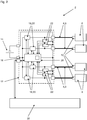
- the motor vehicle supply network 2 shown has a plurality of load current paths 4, via each of which a connected or connected load 6 is supplied with electrical power as required.
- Each load 6 is connected to a power distributor 12 with the aid of a cable 8, which has a connection element designed as a plug 10 at both ends, so that each load current path 4 is formed at least in sections by a cable 8.
- the power distributor 12 is connected to a power source 14 which makes electrical power available in the motor vehicle supply network 2 and feeds it into the power distributor 12 for this purpose.
- a supply current path 16 via which the power distributor 12 is connected to the power source 14 and via which electrical power from the power source 14 reaches the power distributor 12, splits into the load current paths 4, via which the loads 6 are quasi-end consumers be supplied with electrical power.
- the power requirement is between 500 W and 1500 W, depending on the load 6, and the motor vehicle supply network 2 is accordingly designed to supply electrical consumers with a relatively high power requirement.
- the motor vehicle supply network 2 is designed for a motor vehicle and has a safety system with the aid of which the motor vehicle supply network 2 protects against both overcurrent accidents and arcing accidents and consequential damage resulting therefrom is secured.
- the safety system is designed in such a way that each load current path 4 is monitored and that the load 6 supplied via a load current path 4 is cut off from the supply as soon as an impending incident is detected in the corresponding load current path 4.
- the basic principle of monitoring is explained below using the in Fig. 1
- the simplified motor vehicle supply network 2 illustrated which only comprises a load current path 4 and, accordingly, a load 6, is explained.
- This basic principle can, however, be transferred without problems to a plurality of load current paths 4 and, accordingly, to a plurality of loads 6 and thus also in the motor vehicle supply network 2 according to FIG Fig. 2 use.
- the power distributor 12 which is shown in FIG Fig. 1 like in Fig. 2 is marked by a dashed border, a plurality of functional units or functional modules, which in the exemplary embodiment are accommodated on a common printed circuit board and surrounded by a common housing.
- a functional unit is provided by a semiconductor switch 18, which is opened or blocked when an impending incident is detected in order to decouple the load 6 from the supply of electrical energy, i.e. to switch off the electrical consumer that is supplied via the corresponding load current path 4.
- the semiconductor switch 18 is integrated in the corresponding load current path 4 and is also used to switch the corresponding electrical consumer on and off as required.
- the power distributor 12 comprises a current measuring unit 20, with the aid of which the current flowing via the load current path 4 is monitored by detecting the current strength.
- the current measuring unit 20 is connected directly to a current measuring output on the semiconductor switch 18 for signaling purposes, or the current measuring unit 20 is completely integrated into the semiconductor switch 18.
- the power distributor 12 comprises a voltage measuring unit 22, which is divided into a circuit shown in FIG Fig. 1 only partially shown voltage measuring bridge is integrated. This is based on the principle of a Wheadston measuring bridge and is already in the one that goes back to the applicant DE 10 2012 019 996 A1 described, which is why at this point reference is expressly made to this laid-open specification.
- Both the current measuring unit 20 and the voltage measuring unit 22 together with the voltage measuring bridge 24 serve only to record a current strength and a voltage, whereas the evaluation of the recorded measurement data, in particular the time profile of the recorded current intensity and the time profile of the recorded voltage, is carried out in a monitoring unit 26 takes place, which is part of the power distributor 12 as a further functional unit of the security system.
- a monitoring unit 26 there is then a comparison of the current intensity detected by the current measuring unit 20 with several current profiles stored in a memory of the monitoring unit 26 which reproduce a characteristic temporal course of the current intensity before and when an incident occurs, whereby a comparable temporal course of the by means of the current measuring unit 20 detected amperage can be inferred to an impending incident.
- An analog evaluation of the measurement data of the voltage measuring unit 22 takes place in parallel, with several voltage profiles again being stored in the memory of the monitoring unit 26 for this purpose.
- the monitoring unit 26 is designed in such a way that the detection of impending overcurrent accidents is recognized only when a characteristic time profile of the current intensity occurs in the load current path 4, whereas the impending arc accidents are recognized when both a characteristic time profile of the current intensity and a characteristic time profile of the voltage detected by means of the voltage measuring unit 22 is determined. In this way, different types of threatening incidents are recognized as threatening incidents, regardless of the type of threatening incident In the event of a fault, the monitoring unit 26 reacts in such a way that it initiates the opening or blocking of the semiconductor switch 18 and for this purpose transmits a control signal to an amplifier 28.
- a fault log is generated in the monitoring unit 26 and transmitted via a signal output 30 on the power distributor 12 to an external receiver, in the exemplary embodiment a control unit 32 in the vehicle's electrical system.
- the fault log is then incorporated into an error log and stored in an error memory, which is typically read out by a maintenance technician during maintenance of the motor vehicle. This then makes the maintenance technician aware of the problem at hand.
- the error log also contains information on the load current path 4 of the motor vehicle supply network 2 in which the problem is present. Apart from that, the individual load current paths 4 of the motor vehicle supply network 2 are monitored in accordance with Fig. 2 according to the same principle as in the case of the motor vehicle supply network 2 Fig. 1 , a separate semiconductor switch 18, a separate current measuring unit 20 and a separate voltage measuring bridge 24 with an integrated voltage measuring unit 22 being provided for each load current path 4 and being implemented accordingly in the power distributor 12.
- the evaluation of the measurement data belonging to the individual load current paths 4, takes place in a single monitoring unit 26, which is accordingly connected to all of the current measurement units 20 and all of the voltage measurement units 22 in the power distributor 12.
- the one monitoring unit 26 controls the semiconductor switch 18 belonging to the corresponding load current path 4, whereby the corresponding load current path 4 is disconnected from the power supply.
- the control in the exemplary embodiment takes place in accordance with Fig. 2 directly through the Monitoring unit 26, which is constructed in the manner of a microcontroller and has an integrated signal amplifier for controlling the semiconductor switches 18 in the power distributor 12.
- Fig. 1 two resistors 34 shown in the area of the load 6 and a sensor line or signal line 36 are also shown, which are part of the voltage measuring bridge 24 and in Fig. 2 are not explicitly shown, but are implemented for each load current path 4 in the motor vehicle supply network 2.
- the corresponding resistors 34 are in each case integrated in the load-side connector 10 of each cable 8 and the signal line 36 is provided either by an additional wire in each cable 8 or by shielding in each cable 8.
Landscapes
- Engineering & Computer Science (AREA)
- Mechanical Engineering (AREA)
- Power Engineering (AREA)
- Combustion & Propulsion (AREA)
- Physics & Mathematics (AREA)
- General Physics & Mathematics (AREA)
- Chemical & Material Sciences (AREA)
- Transportation (AREA)
- Emergency Protection Circuit Devices (AREA)
- Electric Propulsion And Braking For Vehicles (AREA)
- Direct Current Feeding And Distribution (AREA)
- Control Of Electric Motors In General (AREA)
- Control Of Direct Current Motors (AREA)
Description
Die Erfindung betrifft ein Kraftfahrzeug-Versorgungsnetz und insbesondere ein 48V-Bordnetz eines Kraftfahrzeuges.The invention relates to a motor vehicle supply network and in particular to a 48V on-board network of a motor vehicle.
Derzeit werden Kraftfahrzeuge mit einem Gleichstrom-Versorgungsnetz ausgestattet, welches als sogenanntes 12V-Bordnetz ausgestaltet ist und dementsprechend eine oder mehrere 12V-Spanungsquellen aufweist. Da jedoch die Anzahl der elektrischen Verbraucher in einem Kraftfahrzeug zuletzt von Fahrzeuggeneration zu Fahrzeuggeneration deutlich angestiegen ist, wird das 12V-Bordnetz als nicht zukunftsfähig angesehen.Motor vehicles are currently equipped with a direct current supply network, which is designed as a so-called 12V on-board network and accordingly has one or more 12V voltage sources. However, since the number of electrical consumers in a motor vehicle has recently increased significantly from vehicle generation to vehicle generation, the 12 V on-board network is not regarded as sustainable.
Aktuell sehen die Planungen vieler Automobilhersteller vor, dass das 12V-Bordnetz durch ein 48V-Bordnetz, also wiederum ein Gleichstrom-Versorgungsnetz, abgelöst wird, dass also die Basisspannung, Netzspannung oder Quellspannung für das Gleichstrom-Versorgungsnetz des Kraftfahrzeuges von 12V auf 48V angehoben wird. Wie bereits in der Einleitung der auf die Anmelderin zurückgehenden Offenlegungsschrift
Von besonderer Relevanz ist dabei das erhöhte Risiko, dass sich sogenannte Lichtbögen ausbilden, die zu einem Kabelbrand und infolgedessen auch zu einem Fahrzeugbrand führen können. Entsprechende Lichtbögen entstehen dabei z.B., wenn eine Kabelisolierung durch Reibung an einem benachbarten Bauteil oder einer benachbarten Baugruppe zumindest lokal abgetragen wird und infolgedessen dann ein Leiter des Gleichstrom-Versorgungsnetzes frei liegt und dabei dicht an einer elektrisch leitfähigen Baugruppe, wie dem Fahrzeugskelett, positioniert ist. In einem solchen Fall genügt dann bereits eine Potentialdifferenz zwischen dem frei liegenden Leiter und der leitfähigen Baugruppe von beispielsweise 15V und eine relativ geringe Leistungsübertragung über den frei liegenden Leiter von etwa 50 Watt, damit sich ein Lichtbogen zwischen dem frei liegenden Leiter und der elektrisch leitfähigen Baugruppe ausbildet.Of particular relevance here is the increased risk that so-called arcs are formed, which can lead to a cable fire and consequently to a vehicle fire. Corresponding arcs arise, for example, when a cable insulation is at least locally removed by friction on an adjacent component or an adjacent assembly and as a result a conductor of the direct current supply network is then exposed and positioned close to an electrically conductive assembly such as the vehicle frame. In such a case, a potential difference of 15V, for example, between the exposed conductor and the conductive assembly is sufficient and a relatively low power transfer across the exposed conductor of about 50 watts to create an arc between the exposed conductor and the electrically conductive assembly.
Aus der
Die
Ausgehend hiervon liegt der Erfindung die Aufgabe zugrunde, ein vorteilhaft ausgestaltetes Kraftfahrzeug-Versorgungsnetz anzugeben.Starting from this, the invention is based on the object of specifying an advantageously configured motor vehicle supply network.
Diese Aufgabe wird erfindungsgemäß gelöst durch ein Kraftfahrzeug-Versorgungsnetz mit den Merkmalen des Anspruchs 1 sowie durch einen Leistungsverteiler für ein solches Versorgungsnetz mit den Merkmalen des Anspruchs 13. Bevorzugte Weiterbildungen sind in den rückbezogenen Ansprüchen enthalten.According to the invention, this object is achieved by a motor vehicle supply network with the features of claim 1 and by a power distributor for such a supply network with the features of claim 13. Preferred developments are contained in the dependent claims.
Ein entsprechendes Kraftfahrzeug-Versorgungsnetz ist hierbei insbesondere für ein Kraftfahrzeug ausgelegt und dabei bevorzugt als Gleichstrom-Versorgungsnetz und insbesondere als 48V-Bordnetz (48-Volt-Bordnetz) ausgestaltet. Es umfasst eine Strom- oder Spannungsquelle sowie einen Leistungsverteiler, der zur Einspeisung von Leistung aus der Stromquelle über einen Zuleitungsstrompfad an die Stromquelle angebunden ist, wobei der entsprechende Zuleitungsstrompfad typischerweise zumindest abschnittsweise durch ein Leistungsübertragungskabel, oder kurz Kabel, ausgebildet ist. Weiter umfasst das Kraftfahrzeug-Versorgungsnetz zumindest eine Last, also einen elektrischen Verbraucher, die zur Versorgung mit Leistung aus dem Leistungsverteiler über einen Laststrompfad mit integriertem Halbleiterschalter an den Leistungsverteiler angebunden ist. Hierbei ist auch der Laststrompfad typischerweise zumindest abschnittsweise durch ein Kabel ausgebildet.A corresponding motor vehicle supply network is designed in particular for a motor vehicle and is preferably configured as a direct current supply network and in particular as a 48V on-board network (48-volt on-board network). It includes a current or voltage source and a power distributor that is used to Feeding power from the power source is connected to the power source via a feed line current path, the corresponding feed line current path typically being formed at least in sections by a power transmission cable, or cable for short. Furthermore, the motor vehicle supply network comprises at least one load, that is to say an electrical consumer, which is connected to the power distributor via a load current path with an integrated semiconductor switch in order to be supplied with power from the power distributor. In this case, the load current path is also typically formed at least in sections by a cable.
Der Leistungsverteiler wiederum umfasst eine Strommesseinheit, eine Spannungsmesseinheit sowie eine Überwachungseinheit, die in den Leistungsverteiler integriert und beispielsweise in einem gemeinsamen Gehäuse oder auf einer gemeinsamen Leiterplatine untergebracht sind. Dabei ist die Überwachungseinheit derart eingerichtet, dass diese einen drohenden Störfall im Kraftfahrzeug-Versorgungsnetz und insbesondere im Laststrompfad mit der zumindest einen Last anhand der Messdaten der Strommesseinheit und/oder der Messdaten der Spannungsmesseinheit erkennt und daraufhin ein Abschalten der Last mittels des Halbleiterschalters im Strompfad mit der zumindest einen Last initiiert, wobei sowohl drohende Überstrom-Störfälle als auch drohende Lichtbogen-Störfälle als drohender Störfall erkannt werden.The power distributor in turn comprises a current measuring unit, a voltage measuring unit and a monitoring unit, which are integrated in the power distributor and are accommodated, for example, in a common housing or on a common printed circuit board. The monitoring unit is set up in such a way that it detects an impending incident in the motor vehicle supply network and in particular in the load current path with the at least one load based on the measurement data from the current measurement unit and / or the measurement data from the voltage measurement unit and then switches off the load using the semiconductor switch in the current path initiates at least one load, both impending overcurrent accidents and impending arcing accidents being recognized as impending accidents.
Das hier vorgestellte Kraftfahrzeug-Versorgungsnetz ist somit gegen verschiedene Störfälle abgesichert, so dass daraus resultierende Folgeschäden, insbesondere Kabel- oder Fahrzeugbrände, vermieden werden. Der Begriff Störfall wird dabei im Sinne dieser Anmeldung nicht für das Auftreten eines Fehlers oder Defekts, der die Funktionsfähigkeit des Gleichstrom-Verteilernetzes stört, verwendet, sondern für das Auftreten eines Ereignisses oder Systemzustandes, welches bzw. welcher durch einen Fehler oder einen Defekt im Gleichstrom-Verteilernetz hervorgerufen wird und als potentiell problematisch oder kritisch angesehen wird.The motor vehicle supply network presented here is thus protected against various incidents, so that consequential damage resulting therefrom, in particular cable or vehicle fires, is avoided. In the context of this application, the term accident is not used for the occurrence of an error or defect that disrupts the functionality of the direct current distribution network, but rather for the occurrence of an event or system state which is caused by an error or a defect in the direct current Distribution network and is viewed as potentially problematic or critical.
So ist zum Beispiel das Ansteigen der Stromstärke in einem Strompfad des Gleichstrom-Verteilernetzes auf einen Wert oberhalb der Nennstromstärke, also der vorgesehenen Stromstärke, zwar tendenziell als Systemfehler oder Fehler anzusehen, jedoch ist dieser Fehler nicht zwingend als kritisch zu bewerten. Erst wenn die Stromstärke über einen längeren Zeitraum hinweg über der Nennstromstärke liegt oder sehr deutlich über der Nennstromstärke liegt, ist ein Zustand erreicht, der für das Gleichstrom-Verteilernetz potentiell problematisch ist, da dann ein signifikantes Risiko für die Beschädigung einzelner Baugruppen oder Komponenten des Kraftfahrzeug-Versorgungsnetzes besteht.For example, the increase in the current intensity in a current path of the direct current distribution network to a value above the nominal current intensity, i.e. the intended current strength, although it tends to be viewed as a system error or error, this error is not necessarily to be assessed as critical. Only when the current intensity is above the nominal current intensity for a longer period of time or is very clearly above the nominal current intensity is a condition reached that is potentially problematic for the direct current distribution network, as there is then a significant risk of damage to individual assemblies or components of the motor vehicle Supply network exists.
Eine ähnliche Differenzierung wird weiterhin beispielsweise im Falle eines Kabelbruches vorgenommen. Ein solcher Kabelbruch stellt zwar einen Defekt dar, ist für sich genommen aber noch nicht problematisch oder kritisch. Infolge eines Kabelbruches jedoch kommt es unter Umständen zu einem Überschlag im Bereich des Kabelbruches, also zur Ausbildung eines Lichtbogens, der die Bruchstelle überbrückt, so dass der Strom wieder durch den Strompfad hindurch zur angebundenen Last fließt. Eben dieser Lichtbogen wird als potenziell problematisch oder kritisch angesehen, da dieser einen Kabel- und / oder einen Fahrzeugbrand auslösen kann.A similar differentiation is still made, for example, in the event of a cable break. Such a cable break represents a defect, but is not in itself problematic or critical. As a result of a cable break, however, there may be a flashover in the area of the cable break, i.e. the formation of an arc that bridges the break point so that the current flows again through the current path to the connected load. It is precisely this arc that is viewed as potentially problematic or critical, as it can trigger a cable and / or vehicle fire.
Infolge dessen ist das Schutzsystem des Kraftfahrzeug-Versorgungsnetzes und insbesondere die Überwachungseinheit im Leistungsverteiler bevorzugt derart ausgestaltet, dass dieses bzw. diese bereits reagiert, noch bevor ein kritisches Ereignis auftritt oder ein potenziell problematischer Zustand erreicht ist. Auf diese Weise werden Folgeschäden im Kraftfahrzeug-Versorgungsnetz oder in der unmittelbaren Umgebung vermieden und das Auftreten von Lichtbögen wird unterbunden.As a result, the protection system of the motor vehicle supply network and in particular the monitoring unit in the power distributor is preferably designed in such a way that it responds even before a critical event occurs or a potentially problematic state is reached. In this way, consequential damage in the motor vehicle supply network or in the immediate vicinity is avoided and the occurrence of arcs is prevented.
Weiter stehen die Begriffe drohender Überstrom-Störfall und drohender Lichtbogen-Störfall im Sinne dieser Anmeldung für verschiedene prinzipiell mögliche Bedingungen oder Situationen, auf die das Schutzsystem insbesondere durch Abschalten der zumindest einen Last reagieren soll.Furthermore, the terms impending overcurrent accidents and impending arcing accidents in the context of this application stand for various possible conditions or situations to which the protection system should react, in particular by switching off the at least one load.
Hierbei steht der Begriff drohender Überstrom-Störfall z.B. für ein Ansteigen der Stromstärke aufgrund eines sogenannten Kurzschlusses, infolgedessen die Stromstärke im betroffenen Laststrompfad auf ein Vielfaches der Nennstromstärke, also quasi der vorgesehenen Stromstärke, ansteigt. In diesem Fall ist ein möglichst schnelles Trennen des betroffenen Laststrompfades von der Energiezufuhr und somit ein Abschalten der zumindest einen Last erwünscht und dementsprechend ist die Überwachungseinheit beispielsweise derart eingerichtet, dass ein Öffnen des Halbleiterschalters oder ein Sperren des Halbleiterschalters im Laststrompfad mit der zumindest einen Last durch die Überwachungseinheit initiiert wird, sobald durch die Strommesseinheit ein Wert größer dem 2-fachen der Nennstromstärke messtechnisch erfasst wird.Here, the term impending overcurrent incident stands for an increase in the current strength due to a so-called short circuit, as a result of which Amperage in the affected load current path increases to a multiple of the nominal amperage, so quasi the intended amperage. In this case, the fastest possible disconnection of the load current path concerned from the energy supply and thus switching off the at least one load is desired and accordingly the monitoring unit is set up, for example, in such a way that the semiconductor switch is opened or the semiconductor switch is blocked in the load current path with the at least one load the monitoring unit is initiated as soon as a value greater than twice the nominal current intensity is measured by the current measuring unit.
Eine relativ geringe Überschreitung der Nennstromstärke, beispielsweise bis hin zum 2-fachen Wert, wird dagegen erst dann als drohender Überstrom-Störfall bewertet und erkannt, wenn die Stromstärke im betroffenen Laststrompfad über einen vorgegebenen Zeitraum hinweg oberhalb der Nennstromstärke bleibt. Daher ist die Überwachungseinheit bevorzugt derart eingerichtet, dass diese erst dann eine Öffnung oder Sperrung des Halbleiterschalters im betroffenen Laststrompfad initiiert, wenn die Stromstärke zum Beispiel mindestens 10 s oberhalb der Nennstromstärke bleibt. Auf diese Weise wird berücksichtigt, dass in einem Gleichspannungs-Versorgungsnetz prinzipiell Schwankungen der Stromstärke auftreten können, so dass die Stromstärke in einem Strompfad des Kraftfahrzeug-Versorgungsnetzes zeitweise über dem eigentlich vorgesehenen Wert, also der Nennstromstärke, liegt. Sofern eine solche Überschreitung der Nennstromstärke jedoch nicht allzu groß ausfällt und lediglich über einen begrenzten Zeitraum hinweg anhält, ist das Risiko für einen daraus resultierenden Schaden an einer Baugruppe des Kraftfahrzeug-Versorgungsnetzes und insbesondere an der zumindest einen Last als gering einzustufen und dementsprechend ist die Überwachungseinheit bevorzugt derart ausgestaltet, dass eine kurzzeitige Überschreitung der Nennstromstärke toleriert wird, solange die Stromstärke einen vorgegebenen Grenzwert, der als Hinweis auf einen Kurzschluss angesehen wird, nicht überschreitet. Das heißt also, dass mit Hilfe der Überwachungseinheit nicht nur die beiden typischen prinzipiell möglichen drohenden Überstrom-Störfälle als drohende Störfälle erkannt oder detektiert werden, sondern darüber hinaus bevorzugt auch die Art des drohenden Überstrom-Störfälls erkannt oder ermittelt wird, so dass dann z.B. differenziert auf verschiedene drohende Störfälle reagiert werden kann.A relatively small excess of the rated current, for example up to twice the value, is only assessed and recognized as an impending overcurrent incident if the current in the affected load current path remains above the rated current for a specified period of time. The monitoring unit is therefore preferably set up in such a way that it only initiates an opening or blocking of the semiconductor switch in the relevant load current path when the current strength remains above the nominal current strength, for example for at least 10 s. In this way, it is taken into account that fluctuations in the current intensity can in principle occur in a DC voltage supply network, so that the current intensity in a current path of the motor vehicle supply network is temporarily above the actually intended value, i.e. the nominal current intensity. If such an excess of the rated current is not too great and only lasts for a limited period of time, the risk of resulting damage to an assembly of the motor vehicle supply network and in particular to the at least one load is to be classified as low and the monitoring unit is accordingly preferably designed in such a way that a brief exceeding of the nominal current strength is tolerated as long as the current strength does not exceed a predetermined limit value, which is regarded as an indication of a short circuit. This means that with the help of the monitoring unit not only the two typical impending overcurrent accidents are recognized or detected as impending accidents, but also the type of impending overcurrent accidents is preferably recognized or determined, see above that then, for example, it is possible to react differently to various impending incidents.
Dies gilt jedoch nicht nur für die drohenden Überstrom-Störfälle, sondern darüber hinaus auch für die drohenden Lichtbogen-Störfälle, wobei eben je nach Ausführungsvariante des Kraftfahrzeug-Versorgungsnetzes und insbesondere je nach Ausgestaltung der Überwachungseinheit entweder verschiedene drohende Störfälle lediglich detektiert werden oder aber zudem identifiziert werden. Auf diese Weise ist eine Anpassung an verschiedene Anwendungszwecke möglich und die daraus resultierende Gestaltungsfreiheit wird bevorzugt auch genutzt. Im einfachsten Fall ist dann die Überwachungseinheit derart ausgebildet, dass die verschiedensten, oder zumindest die als besonders relevant angesehenen, prinzipiell möglichen drohenden Störfälle detektiert, also erkannt werden, ohne zwischen den verschiedenen drohenden Störfällen zu differenzieren, also ohne dass erkannt wird, welcher Störfall genau droht einzutreten. In diesem Fall erfolgt dann dementsprechend unabhängig von der Art des drohenden Störfalls dieselbe Reaktion durch das System, also insbesondere das Öffnen oder Sperren des Halbleiterschalters im Strompfad mit der zumindest einen Last, wobei die Überwachungseinheit den entsprechenden Halbleiterschalter entweder über eine entsprechende Verbindung zwischen dem Halbleiterschalter und der Überwachungseinheit direkt ansteuert oder eine entsprechende Ansteuerung initiiert, indem diese z.B. eine Art Triggersignal an eine Endstufe oder Verstärkerstufe übermittelt, welche zur Ansteuerung des Halbleiterschalters eingesetzt wird.However, this applies not only to the impending overcurrent accidents, but also to the impending arcing accidents, whereby depending on the variant of the motor vehicle supply network and in particular depending on the design of the monitoring unit, either various impending accidents are merely detected or also identified will. In this way, adaptation to different purposes is possible and the resulting freedom of design is also used with preference. In the simplest case, the monitoring unit is designed in such a way that the most diverse, or at least those which are considered to be particularly relevant, in principle possible impending accidents are detected, i.e. recognized without differentiating between the various impending accidents, i.e. without identifying which incident exactly threatens to occur. In this case, regardless of the type of impending incident, the system reacts accordingly, i.e. in particular the opening or blocking of the semiconductor switch in the current path with the at least one load controls the monitoring unit directly or initiates a corresponding control, for example by transmitting a type of trigger signal to an output stage or amplifier stage which is used to control the semiconductor switch.
Dabei werden auch unter dem Begriff drohender Lichtbogen-Störfall typischerweise verschiedene, teilweise in der
Hierbei ist das generelle Risiko für Lichtbögen umso höher, je höher die im Kraftfahrzeug-Versorgungsnetz zur Verfügung gestellte Spannung ist und je höher die über einen Strompfad geleitete Leistung ist. Aus diesem Grund werden bevorzugt Kraftfahrzeug-Versorgungsnetze mit einem hier vorgestellten integrierten Sicherungssystem versehen, für die eine Quellspannung oder Netzspannung größer 20 Volt vorgesehen ist, in die also zumindest eine Spannungsquelle mit einer Versorgungsspannung größer 20 Volt eingebunden ist. Weiter bevorzugt ist eine entsprechende Ausgestaltung für Kraftfahrzeug-Versorgungsnetze vorgesehen, die zumindest einen Strompfad und insbesondere einen Laststrompfad aufweisen, über welchen im Betrieb zumindest zeitweise mehr als 300 Watt und insbesondere mehr als 500 Watt, also beispielsweise etwa 1.000 Watt, zur Versorgung einer Last, also eines elektrischen Verbrauchers, geleitet werden. Bei derartigen Kraftfahrzeug-Versorgungsnetzen wird das Risiko für entsprechende Lichtbögen als nicht vernachlässigbar angesehen und dementsprechend werden diese Kraftfahrzeug-Versorgungsnetze nicht nur gegen Überströme sondern eben auch gegen Lichtbögen abgesichert.The general risk of arcing is higher, the higher the voltage made available in the motor vehicle supply network and the higher the power conducted via a current path. For this reason, motor vehicle supply networks are preferably provided with an integrated fuse system presented here, for which a source voltage or mains voltage greater than 20 volts is provided, i.e. in which at least one voltage source with a supply voltage greater than 20 volts is integrated. A corresponding configuration for motor vehicle supply networks is also preferably provided, which has at least one current path and in particular one load current path, via which at least at times more than 300 watts and in particular more than 500 watts, for example about 1,000 watts, to supply a load, that is, an electrical consumer. In the case of such motor vehicle supply networks, the risk of such arcs is not considered to be negligible and accordingly these motor vehicle supply networks are protected not only against overcurrents but also against arcs.
Weiter sind bevorzugt je nach Ausführungsvariante alle oder zumindest die wesentlichen Funktionselemente, die zur Überwachung und somit zur Absicherung des Kraftfahrzeug-Versorgungsnetzes dienen, Teil des Leistungsverteilers und somit Teil einer einzigen für die Herstellung des Kraftfahrzeug-Versorgungsnetzes vorgefertigten Baueinheit. Dabei gilt es beispielsweise zu bedenken, dass heutzutage Bordnetze für Kraftfahrzeuge häufig mit Hilfe einer begrenzten Anzahl vorgefertigter Baueinheiten hergestellt werden, wobei die vorgefertigten Baueinheiten nach dem Baukasten-Prinzip auf verschiedene Weise miteinander kombiniert werden, um unterschiedliche Bordnetz-Varianten oder Bordnetz-Ausführungen zu realisieren. Durch eine Integration der für eine Absicherung vorgesehenen Funktionseinheiten in den Leistungsverteiler, also eine ohnehin vorgesehene vorgefertigte Baueinheit, kann auf einen zusätzlichen Baukasten-Baustein oder eine zusätzliche vorgefertigte Baueinheit für die Funktionselemente zur Absicherung des Kraftfahrzeug-Versorgungsnetzes verzichtet werden. Hierbei sind bevorzugt zumindest die wesentlichen Funktionseinheiten, also die Strommesseinheit, die Spannungsmesseinheit und die Überwachungseinheit, z.B. in einem gemeinsamen Gehäuse, dem Gehäuse des Leistungsverteilers, untergebracht und/oder auf einer gemeinsamen Leiterplatine realisiert.Furthermore, depending on the embodiment variant, all or at least the essential functional elements that serve to monitor and thus protect the motor vehicle supply network are preferably part of the power distributor and thus part of a single unit prefabricated for the production of the motor vehicle supply network. It should be borne in mind, for example, that nowadays electrical systems for motor vehicles are often produced with the help of a limited number of prefabricated structural units, with the prefabricated structural units being combined with one another according to the modular principle in various ways in order to implement different electrical system variants or designs . By integrating the functional units provided for protection in the power distributor, i.e. a prefabricated unit that is provided anyway, an additional modular module or an additional prefabricated unit for the functional elements for protecting the motor vehicle supply network can be dispensed with. In this case, at least the essential functional units, i.e. the current measuring unit, the voltage measuring unit and the monitoring unit, are preferably in a common housing, the housing of the power distributor, housed and / or implemented on a common printed circuit board.
Der Leistungsverteiler ist zudem derart ausgestaltet, dass sich der Zuleitungsstrompfad im Leistungsverteiler quasi in mehrere Laststrompfade aufspaltet, wobei über jeden dieser Lastrompfade eine Last an den Leistungsverteiler angebunden ist. Dementsprechend wird dann, ganz im Sinne des Begriffes Leistungsverteiler, die von der Stromquelle zur Verfügung gestellte elektrische Leistung im Leistungsverteiler bedarfsgerecht auf die verschiedenen angebundenen Lasten verteilt, so dass jede Last im Bedarfsfall mit ausreichend Leistung versorgt wird. Dabei ist in jeden Laststrompfad ein eigener Halbleiterschalter integriert und jeder Laststrompfad wird auf Störfälle hin überwacht. Je nach Ausgestaltungsvariante sind hierbei für jeden Laststrompfad auch eine eigene Strommesseinheit und/oder eine eigene Spannungsmesseinheit vorgesehen, mit deren Hilfe laststrompfadabhängige Strom- und Spannungsmessungen ermöglicht sind. Für die Überwachung der entsprechenden Messwerte ist hingegen bevorzugt nur eine einzige Überwachungseinheit vorgesehen und dementsprechend im Leistungsverteiler untergebracht. Das heißt also, dass bevorzugt alle vom Leistungsverteiler ausgehenden Laststrompfade durch eine einzige Überwachungseinheit überwacht werden, in dem diese Überwachungseinheit die Messdaten aller Strommesseinheiten und aller Spannungsmesseinheiten auswertet.The power distributor is also designed in such a way that the supply line current path in the power distributor splits into several load current paths, with a load being connected to the power distributor via each of these load current paths. Correspondingly, in the sense of the term power distributor, the electrical power made available by the power source is then distributed to the various connected loads in the power distributor as required, so that each load is supplied with sufficient power when required. A separate semiconductor switch is integrated into each load current path and each load current path is monitored for faults. Depending on the design variant, a separate current measuring unit and / or a separate voltage measuring unit are also provided for each load current path, with the aid of which load current path-dependent current and voltage measurements are made possible. In contrast, only a single monitoring unit is preferably provided for monitoring the corresponding measured values and is accordingly accommodated in the power distributor. This means that all load current paths emanating from the power distributor are preferably monitored by a single monitoring unit, in which this monitoring unit evaluates the measurement data of all current measuring units and all voltage measuring units.
Hierbei ist die Überwachungseinheit zweckdienlicherweise zudem derart ausgestaltet, dass diese nicht nur einen drohenden Störfall, also einen drohenden Überstrom-Störfall oder einen drohenden Lichtbogen-Störfall, erkennt, sondern darüber hinaus auch in welchem Laststrompfad der Störfall droht, wobei dann lediglich die Last des betroffenen Laststrompfades abgeschaltet wird, in dem die Öffnung oder Sperrung des entsprechenden Halbleiterschalters durch die Überwachungseinheit initiiert wird.In this case, the monitoring unit is expediently designed in such a way that it not only detects an imminent incident, i.e. an imminent overcurrent incident or an imminent arc incident, but also in which load current path the incident is threatening, in which case only the load of the person concerned Load current path is switched off, in which the opening or blocking of the corresponding semiconductor switch is initiated by the monitoring unit.
Weiter ist gemäß einer vorteilhaften Ausgestaltung der Halbleiterschalter als Leistungstransistor und insbesondere als MOSFET ausgebildet, also als Metall-Oxid-Halbleiter-Feldeffekttransistor. MOSFETs lassen sich problemlos für hohe Leistungen bis hin zu mehreren 100 A und bis etwa 1.000 V auslegen (Leistungs-MOSFET) und zeichnen sich gleichzeitig durch kurze Schaltzeiten aus, wodurch derartige Transistoren prinzipielle gut geeignet sind, um Schutzschalter oder Sicherungs-Schalter zur Absicherung eines Kraftfahrzeug-Versorgungsnetzes zu realisieren.Furthermore, according to an advantageous embodiment, the semiconductor switch is designed as a power transistor and in particular as a MOSFET, that is to say as a metal-oxide-semiconductor field effect transistor. MOSFETs can easily be used for high powers up to several 100 A and up to about 1,000 V (power MOSFET) and are characterized at the same time by short switching times, which means that such transistors are in principle well suited for implementing circuit breakers or fuse switches to protect a motor vehicle supply network.
Zudem lassen sich problemlos integrierte Schaltungen mit Hilfe entsprechender Leistungstransistoren bzw. MOSFETs aufbauen, wodurch sich zum Beispiel auch Halbleiterschalter oder Sicherungsschalter mit zusätzlichen Funktionen herstellen und im Kraftfahrzeug-Versorgungsnetz einsetzen lassen. Das heißt also, dass der Halbleiterschalter nicht zwingend durch einen einzelnen Transistor gegeben ist, sondern je nach Anwendungszweck auch komplexer aufgebaut sein kann und aufgebaut ist. So ist es unter anderem vorteilhaft, wenn in einen solchen Halbleiterschalter eine Strommesseinheit integriert ist, die die Stromstärke des über den Halbleiterschalter in einen Laststrompfad fließenden Stroms messtechnisch erfasst. Als Beispiel für einen solchen Halbleiterschalter mit zusätzlichen Funktionen sei an dieser Stelle auf die Serie oder Produktreihe PROFET™ der Firma Infineon verwiesen.In addition, integrated circuits can be built without any problems with the aid of corresponding power transistors or MOSFETs, whereby, for example, semiconductor switches or fuse switches with additional functions can also be produced and used in the motor vehicle supply network. This means that the semiconductor switch is not necessarily given by a single transistor, but can also be constructed and constructed in a more complex manner depending on the application. It is therefore advantageous, inter alia, if a current measuring unit is integrated into such a semiconductor switch, which measures the current intensity of the current flowing into a load current path via the semiconductor switch. As an example of such a semiconductor switch with additional functions at this point, reference is made to the series or product line PROFET ™ from Infineon.
In bevorzugter Ausgestaltung sind auf einer gemeinsamen Leiterplatine für jede der Lasten ein jeweiliger Halbleiterschalter, eine jeweilige Strommesseinheit, eine jeweilige Spannungsmesseinheit sowie eine für alle Lasten gemeinsame Überwachungseinheit angeordnet. Sämtliche Elemente für die Überwachung sind daher kompakt auf einer gemeinsamen Leiterplatte, zumindest in einer gemeinsamen Komponente (Leistungsverteiler) integriert. Diese braucht eingangsseitig nur noch an die Stromquelle angeschlossen werden und abgangsseitig mehrere Anschlüsse (z.B. Steckanschlüsse) für die einzelnen Lastpfade aufweisen.In a preferred embodiment, a respective semiconductor switch, a respective current measuring unit, a respective voltage measuring unit and a monitoring unit common for all loads are arranged on a common printed circuit board for each of the loads. All elements for monitoring are therefore compactly integrated on a common printed circuit board, at least in a common component (power distributor). This only needs to be connected to the power source on the input side and has several connections (e.g. plug-in connections) for the individual load paths on the output side.
Weiterhin handelt es sich bei der Überwachungseinheit zweckdienlicherweise um eine universelle Überwachungseinheit, über die mehrere potentielle Störfälle überwacht werden. So ist die Überwachungseinheit vorzugsweise für jede der einzelnen Lasten zur Erfassung
- eines Überstroms,
- eines Kurzschlusses des Laststrompfades gegen Masse,
- eines parallelen Lichtbogens im Laststrompfad,
- eines seriellen Lichtbogens im Laststrompfad sowie zur Erfassung
- eines seriellen Lichtbogens in einem Massepfad zwischen der jeweiligen Last und einem Massepotenzial ausgebildet.
- an overcurrent,
- a short circuit of the load current path to ground,
- a parallel arc in the load current path,
- a serial arc in the load current path as well as for detection
- of a serial arc formed in a ground path between the respective load and a ground potential.
Die Überwachungseinheit ist bevorzugt nicht nur ausgebildet, um die verschiedensten drohenden Störfälle zu erkennen, sondern darüber hinaus auch, um was für einen drohenden Störfall es sich handelt, welcher Typ Störfall also droht einzutreten. Hierbei wird weiter bevorzugt nicht nur zwischen drohenden Überstrom-Störfällen und drohenden Lichtbogen-Störfällen unterschieden, stattdessen erfolgt in der Regel eine darüber hinausgehende Differenzierung, also unter anderem eine Differenzierung zwischen einem drohenden Überstrom-Störfall aufgrund eines Kurzschlusses und einem drohenden Überstrom-Störfall, bei dem die Stromstärke über einen längeren Zeitraum hinweg größer als die Nennstromstärke und kleiner als zum Beispiel das 2-fache der Nennstromstärke ist.The monitoring unit is preferably designed not only to recognize the most varied of imminent accidents, but also what kind of imminent incident it is, that is, which type of incident is threatening to occur. It is further preferred not only to differentiate between impending overcurrent accidents and impending arcing accidents; instead, as a rule, there is a further differentiation, i.e., among other things, a differentiation between an impending overcurrent accident due to a short circuit and an impending overcurrent accident where the amperage is greater than the nominal amperage and less than, for example, twice the nominal amperage over a longer period of time.
Auch ist die Überwachungseinheit bevorzugt ausgebildet, um zwischen verschiedenen drohenden Lichtbogen-Störfällen zu unterscheiden, also insbesondere zwischen einem drohenden sogenannten seriellen Lichtbogen-Störfall und einem drohenden sogenannten parallelen Lichtbogen-Störfall. Dabei wird zum Beispiel von einem drohenden seriellen Lichtbogen-Störfall gesprochen, wenn in einem Abschnitt eines Laststrompfades, der durch einen Leiterdraht oder ein Kabel ausgebildet ist, ein Kabelbruch oder Drahtbruch vorliegt oder die Leitfähigkeit aus irgendeinem anderen Grund quasi punktuell signifikant abgesetzt ist. In diesem Fall ist dann der Stromfluss im Bereich des Kabelbruches oder Drahtbruches unterbrochen oder zumindest stark reduziert, was zu einem Ladungsstau und somit zu einer relativ hohen Potentialdifferenz über eine relativ kleine Wegstrecke hinweg führt. Bei ausreichend hohem Ladungsstau bildet sich dann ein Lichtbogen aus, der die Bruchstelle oder den defekten Abschnitt überbrückt, so dass wiederum Strom quasi seriell entlang des Strompfades hin zur Last fließt. Das Auftreten des Lichtbogens ist dabei gleichzusetzen mit dem Auftreten des seriellen Lichtbogen-Störfalls.The monitoring unit is also preferably designed to distinguish between different impending arcing incidents, that is to say in particular between an imminent so-called serial arcing incident and an imminent so-called parallel arcing incident. For example, there is an imminent serial arc fault if there is a cable break or wire break in a section of a load current path that is formed by a conductor wire or a cable or the conductivity is significantly reduced at certain points for some other reason. In this case, the current flow in the area of the cable break or wire break is interrupted or at least greatly reduced, which leads to a charge accumulation and thus to a relatively high potential difference over a relatively short distance. If the charge accumulation is sufficiently high, an arc then forms which bridges the break point or the defective section, so that in turn current flows quasi serially along the current path to the load. The occurrence of the arc is to be equated with the occurrence of the serial arc fault.
Dagegen wird von einem parallelen Lichtbogen-Störfall gesprochen, wenn zumindest ein Teil des Stroms über einen Lichtbogen aus dem Laststrompfad heraus in einen anderen Strompfad oder einfach eine Ladungsträgersenke abfließt. Dies geschieht beispielsweise, wenn, wie Eingangs bereits dargelegt, die Isolierung eines Kabels beschädigt wird und daraufhin ein darunter liegender Leiter zumindest Abschnittsweise frei liegt und in einem relativ kurzen Abstand zu einer leitenden Struktur, wie beispielsweise einer Fahrzeugkarosserie, positioniert ist. In diesem Fall wirkt dann die Fahrzeugkarosserie oder das Fahrzeugskelett als Masse oder Masseanschluss und somit als Ladungsträgersenke für den leistungsübertragenden Laststrompfad.On the other hand, it is referred to as a parallel arc fault if at least part of the current flows through an arc from the load current path into another current path or simply a charge carrier sink. This happens, for example, if, as already stated at the beginning, the insulation of a cable is damaged and an underlying conductor is then exposed at least in sections and is positioned at a relatively short distance from a conductive structure such as a vehicle body. In this case, the vehicle body or the vehicle skeleton then acts as a ground or ground connection and thus as a charge carrier sink for the power-transmitting load current path.
Ist die Überwachungseinheit nun für eine Differenzierung oder eine differenzierte Erkennung verschiedener drohender Störfälle ausgebildet, so lassen sich diese Informationen auf unterschiedliche Weise nutzen. Wie bereits zuvor geschrieben, ist es dabei zum Beispiel vorgesehen, das Gleichstrom-Verteilernetz so auszugestalten, dass unterschiedliche drohende Störfälle auch unterschiedliche Reaktionen zur Folge haben, dass also zum Beispiel die Überwachungseinheit derart eingerichtet ist, dass diese ein Abschalten von Halbleiterschaltern je nach drohendem Störfall entweder unmittelbar nach Erkennung eines Stromwertes größer als der Nennstromwert oder aber mit vorgegebener Zeitverzögerung initiiert.If the monitoring unit is now designed for a differentiation or a differentiated detection of different impending incidents, then this information can be used in different ways. As already written before, it is intended, for example, to design the direct current distribution network in such a way that that different impending incidents also result in different reactions, so that for example the monitoring unit is set up in such a way that it initiates switching off of semiconductor switches depending on the impending incident either immediately after detecting a current value greater than the nominal current value or with a predetermined time delay.
Alternativ oder ergänzend hierzu lassen sich diese Informationen an einen nicht im Leistungsverteiler angeordneten, externen Empfänger übermitteln, also zum Beispiel an ein Steuergerät im Bordnetz des Kraftfahrzeuges. Hier werden die Informationen dann beispielsweise in ein Fehlerprotokoll eingefügt und zusammen mit dem Fehlerprotokoll in einem Fehlerspeicher hinterlegt, so dass ein Wartungstechniker, der den Fehlerspeicher im Rahmen einer Wartung ausliest, auf den entsprechenden Fehler sowie Details zum Fehler hingewiesen wird. Alternativ oder ergänzend hierzu löst eine entsprechende Datenübermittlung an das Steuergerät die Generierung eines Warnsignals durch das Steuergerät aus, die den Fahrzeugführer des Kraftfahrzeuges optisch und / oder akustisch darauf hinweist, dass ein Problem vorliegt und das Aufsuchen einer Werkstatt ratsam oder notwendig ist. Ist eine solche Datenübermittlung an einen externen Empfänger vorgesehen, so weist die Überwachungseinheit hierfür bevorzugt eine Kommunikationseinheit auf, die derart eingerichtet ist, dass bei einer Erkennung eines drohenden Störfalls ein in der Kommunikationseinheit generiertes Störfallprotokoll über einen Signalausgang am Leistungsverteiler ausgegeben und, sofern angeschlossen, an einen externen Empfänger übermittelt wird.As an alternative or in addition to this, this information can be transmitted to an external receiver that is not arranged in the power distributor, that is to say, for example, to a control device in the on-board network of the motor vehicle. Here, the information is then inserted into an error log, for example, and stored together with the error log in an error memory so that a maintenance technician who reads out the error memory as part of maintenance work is informed of the relevant error and details of the error. Alternatively or in addition to this, a corresponding data transmission to the control unit triggers the generation of a warning signal by the control unit, which visually and / or acoustically indicates to the driver of the motor vehicle that there is a problem and that it is advisable or necessary to visit a workshop. If such data transmission is provided to an external receiver, the monitoring unit preferably has a communication unit for this purpose, which is set up in such a way that, when an impending incident is detected, an incident log generated in the communication unit is output via a signal output on the power distributor and, if connected, instructs it is transmitted to an external recipient.
In einigen Anwendungsfällen werden die entsprechenden Informationen zudem zusätzlich genutzt, um auf deren Basis ein Anzeigeelement, insbesondere eine Kontrollanzeige, anzusteuern. Die entsprechende Anzeige ist dabei zum Beispiel in ein Gehäuse des Leistungsverteilers integriert oder an einem Gehäuse des Leistungsverteilers angebracht und dient so zur Unterstützung eines Wartungstechnikers bei der Suche nach dem betroffenen Bauteil, was insbesondere dann von Vorteil ist, wenn mehrere derartige Leistungsverteiler in einem Kraftfahrzeug verbaut sind.In some application cases, the corresponding information is also used to control a display element, in particular a control display, on the basis thereof. The corresponding display is integrated, for example, in a housing of the power distributor or attached to a housing of the power distributor and thus serves to support a maintenance technician in the search for the affected component, which is particularly advantageous when several such power distributors are installed in a motor vehicle are.
Um eine entsprechende Differenzierung zwischen verschiedenen drohenden Störfällen zu ermöglichen ist die Überwachungseinheit vorteilhafterweise derart ausgebildet, dass die mittels der Strommesseinheit und / oder mittels der Spannungsmesseinheit generierten Messdaten mit hinterlegten Strom- und / oder Spannungsprofilen verglichen werden, die für bestimmte Störfälle charakteristisch sind. Unter einem Profil ist dabei der zeitliche Verlauf eines Strom- oder Spannungswertes zu verstehen, also die zeitliche Entwicklung eines Strom- oder Spannungswertes vor und beim Auftreten eines Störfalls. Dabei lässt sich aus dem zeitlichen Verlauf nicht nur herauslesen, wann ein Störfall vorliegt, stattdessen ist es auch möglich, einen sich anbahnenden oder drohenden Störfall auszumachen, und infolge dessen zu reagieren, bevor der Störfall tatsächlich auftritt.In order to enable a corresponding differentiation between different impending incidents, the monitoring unit is advantageously designed in such a way that the measurement data generated by means of the current measuring unit and / or by means of the voltage measuring unit are compared with stored current and / or voltage profiles that are characteristic of certain incidents. In this context, a profile is to be understood as the course of a current or voltage value over time, i.e. the development of a current or voltage value over time before and when an incident occurs. It is not only possible to read out from the chronological sequence when an incident is present, instead it is also possible to identify an impending or threatening incident and to react as a result before the incident actually occurs.
Im Falle des zuvor beschriebenen drohenden seriellen Lichtbogen-Störfalls wird das Auftreten eines Lichtbogens als seriellen Lichtbogen-Störfall betrachtet, den es zu unterbinden gilt. Bevor sich jedoch ein entsprechender Lichtbogen ausgebildet, verändern sich bereits die Strom- und / oder Spannungswerte beim betroffenen Laststrompfad in charakteristischer Weise und diese Änderung lässt sich durch einen Vergleich der Messwerte oder vielmehr durch einen Vergleich der zeitlichen Entwicklung der Messwerte mit einem hinterlegten Messwerteprofil erkennen.In the case of the threatened serial arc accident described above, the occurrence of an arc is regarded as a serial arc accident which must be prevented. However, before a corresponding arc is formed, the current and / or voltage values in the affected load current path change in a characteristic way and this change can be recognized by comparing the measured values or rather by comparing the development of the measured values over time with a stored measured value profile.
Während die für einen Laststrompfad vorgesehene Strommesseinheit, wie zuvor beschrieben, bevorzugt in den Halbleiterschalter des entsprechenden Laststrompfades integriert ist, ist die diesem Laststrompfad zugeordnete Spannungsmesseinheit vorzugsweise Teil einer Messbrücke, dient also zur Erfassung einer Potentialdifferenz in einer Messbrücke mit einem Brückenkopf im Bereich der Last des entsprechenden Laststrompfades und mit einem Brückenkopf im Bereich des Halbleiterschalters dieses Laststrompfades. In diesem Fall sind dann alle Baugruppen oder Komponenten, die zur Realisierung einer Überwachung und Absicherung des entsprechenden Laststrompfades dienen, mit Ausnahme des Brückenkopfes im Bereich der Last Teil des Leistungsverteilers und dementsprechend im Leistungsverteiler untergebracht. Dabei ist die Messbrücke weiter bevorzugt nach Art einer sogenannten Wheatstone'schen Messbrücke ausgestaltet, basiert also auf dem Prinzip der bekannten Wheatstone'schen Messbrücke. In diesem Fall wird dann eine Spannungsmessung oder Spannungsüberwachung vorgenommen, wie sie in der
Wie in der Offenlegungsschrift dargelegt umfasst die Messbrücke dabei typischerweise eine Sensorleitung oder Signalleitung, die den Brückenkopf im Bereich der Last mit der Spannungsmesseinheit im Leistungsverteiler verbindet. Dabei ist die Sensorleitung zumindest in einem Abschnitt durch eine Ader oder eine Schirmung eines Leistungsübertragungs-Kabels ausgebildet, dessen übrige Adern bzw. dessen Leiter den Laststrompfad in eben diesem Abschnitt ausbilden bzw. ausbildet.As set out in the laid-open specification, the measuring bridge typically comprises a sensor line or signal line that connects the bridge head in the area of the load with the voltage measuring unit in the power distributor. In this case, the sensor line is formed at least in one section by a wire or a shielding of a power transmission cable, the remaining wires or the conductor of which form the load current path in precisely this section.
Weiter bevorzugt ist der Brückenkopf im Bereich der Last wie im zweiten Ausführungsbeispiel der
Die Kombination der in einem Steckverbinder integrierten Brückenkopfes mit der in den Laststrompfad integrierten Sensorleitung (separate Ader oder Schirmung) in Verbindung mit der gemeinsamen Überwachungskomponente (Leistungsverteiler), in bzw. auf der sämtliche erforderliche Elemente für die Überwachung integriert sind, hat den besonderen Vorteil, dass sämtliche Maßnahmen zur Leitungsüberwachung universell bereits vorab bereitgestellt werden können, ohne dass weitere aufwändige Konfektionierungsmaßnahmen erforderlich sind.The combination of the bridgehead integrated in a connector with the sensor line integrated in the load current path (separate wire or shielding) in connection with the common monitoring component (power distributor), in or on which all the necessary elements for monitoring are integrated, has the particular advantage: that all measures for line monitoring can be universally provided in advance without the need for further complex assembly measures.
Ausführungsbeispiele der Erfindung werden nachfolgend anhand einer schematischen Zeichnung näher erläutert. Darin zeigen:
- FIG 1
- in einem Blockschaltbild ein Gleichstrom-Verteilernetz sowie
- FIG 2
- in einem Blockschaltbild ein alternatives Gleichstrom-Verteilernetz.
- FIG 1
- in a block diagram a direct current distribution network as well
- FIG 2
- in a block diagram an alternative direct current distribution network.
Einander entsprechende Teile sind in allen Figuren jeweils mit den gleichen Bezugszeichen versehen.Corresponding parts are provided with the same reference symbols in each of the figures.
Ein nachfolgend exemplarisch beschriebenes und in
Der Leistungsverteiler 12 wiederum ist an eine Stromquelle 14 angebunden, welche elektrische Leistung im Kraftfahrzeug-Versorgungsnetz 2 zur Verfügung stellt und hierfür in den Leistungsverteiler 12 einspeist. Im Leistungsverteiler 12 spaltet sich dann ein Zuleitungsstrompfad 16, über den der Leistungsverteiler 12 an die Stromquelle 14 angebunden ist und über welchen elektrische Leistung aus der Stromquelle 14 in den Leistungsverteiler 12 gelangt, in die Laststrompfade 4 auf, über welche die Lasten 6 quasi als Endverbraucher mit elektrischer Leistung versorgt werden. Dabei liegt der Leistungsbedarf je nach Last 6 zwischen 500 W und 1500 W und dementsprechend ist das Kraftfahrzeug-Versorgungsnetz 2 ausgebildet, um elektrische Verbraucher mit einem relativ hohen Leistungsbedarf zu versorgen.The
Weiter ist das Kraftfahrzeug-Versorgungsnetz 2 im hier beschriebenen Ausführungsbeispiel für ein Kraftfahrzeug ausgelegt und weist ein Sicherungssystem auf, mit dessen Hilfe das Kraftfahrzeug-Versorgungsnetz 2 sowohl gegen Überstrom-Störfälle als auch gegen Lichtbogen-Störfälle und somit daraus resultierende Folgeschäden abgesichert ist. Dabei ist das Sicherungssystem derart ausgestaltet, dass jeder Laststrompfad 4 überwacht wird und das die über einen Laststrompfad 4 versorgte Last 6 von der Versorgung abgeschnitten wird, sobald ein drohender Störfall im entsprechenden Laststrompfad 4 erkannt wird.Furthermore, in the exemplary embodiment described here, the motor
Das Grundprinzip der Überwachung wird nachfolgend anhand des in
Zur Überwachung des Laststrompfades 4 und somit zur Realisierung des Sicherungssystems des Kraftfahrzeug-Versorgungsnetzes 2 weist der Leistungsverteiler 12, der in
Eine Funktionseinheit ist durch einen Halbleiterschalter 18 gegeben, der bei Erkennung eines drohenden Störfalls geöffnet oder gesperrt wird, um so die Last 6 von der Versorgung mit elektrischer Energie abzukoppeln, also um den elektrischen Verbraucher, der über den entsprechenden Lastrompfad 4 versorgt wird, abzuschalten. Dabei ist der Halbleiterschalter 18 in den entsprechenden Laststrompfad 4 integriert und dient zusätzlich zum An- und Ausschalten des entsprechenden elektrischen Verbrauchers gemäß Bedarf.A functional unit is provided by a
Als weitere Funktionseinheit umfasst der Leistungsverteiler 12 eine Strommesseinheit 20, mit deren Hilfe der über den Laststrompfad 4 fließende Strom durch Erfassung der Stromstärke überwacht wird. Die Strommesseinheit 20 ist hierzu unmittelbar an einen Strommessausgang am Halbleiterschalter 18 signaltechnisch angeschlossen oder aber die Stromesseinheit 20 ist vollständig in den Halbleiterschalter 18 integriert.As a further functional unit, the
Ergänzend zur Strommesseinheit 20 umfasst der Leistungsverteiler 12 eine Spannungsmesseinheit 22, die in eine in
Hierbei dienen sowohl die Strommesseinheit 20 als auch die Spannungsmesseinheit 22 mitsamt der Spannungsmessbrücke 24 lediglich zur Erfassung einer Stromstärke und einer Spannung, wohingegen die Auswertung der erfassten Messdaten, insbesondere des zeitlichen Verlaufs der erfassten Stromstärke und des zeitlichen Verlaufs der erfassten Spannung, in einer Überwachungseinheit 26 erfolgt, die als weitere Funktionseinheit des Sicherungssystems Bestandteil des Leistungsverteiler 12 ist. In der Überwachungseinheit 26 erfolgt dann ein Vergleich der mittels der Strommesseinheit 20 erfassten Stromstärke mit mehreren in einem Speicher der Überwachungseinheit 26 hinterlegten Stromprofilen die einen charakteristischen zeitlichen Verlauf der Stromstärke vor und beim Auftreten eines Störfalls wiedergeben, wodurch bei einer messtechnischen Erfassung eines vergleichbaren zeitlichen Verlaufs der mittels der Strommesseinheit 20 erfassten Stromstärke auf einen drohenden Störfall geschlossen werden kann. Parallel erfolgt eine analoge Auswertung der Messdaten der Spannungsmesseinheit 22, wobei auch hierfür wiederum mehrere Spannungsprofile im Speicher der Überwachungseinheit 26 hinterlegt sind.Both the
Dabei ist die Überwachungseinheit 26 derart ausgelegt, dass die Erkennung von drohenden Überstrom-Störfällen allein beim Auftreten eines charakteristischen zeitlichen Verlaufs der Stromstärke im Laststrompfad 4 erkannt wird, wohingegen die drohenden Lichtbogen-Störfälle erkannt werden, wenn sowohl ein charakteristischer zeitlicher Verlauf der Stromstärke als auch ein charakteristischer zeitlicher Verlauf der mittels der Spannungsmesseinheit 22 erfassten Spannung ermittelt wird. Auf diese Weise werden dann verschiedene Arten von drohenden Störfällen als drohende Störfälle erkannt, wobei unabhängig von der Art des drohenden Störfalls eine Reaktion der Überwachungseinheit 26 derart erfolgt, dass dieser die Öffnung oder Sperrung des Halbleiterschalters 18 initiiert, und hierfür ein Steuersignal an einen Verstärker 28 übermittelt.The
Zusätzlich wird bei einem Auftreten eines drohenden Störfalls in der Überwachungseinheit 26 ein Störprotokoll generiert und über einen Signalausgang 30 am Leistungsverteiler 12 an einen externen Empfänger, im Ausführungsbeispiel ein Steuergerät 32 im Bordnetz des Kraftfahrzeuges, übermittelt. Im Steuergerät 32 wird das Störprotokoll dann in ein Fehlerprotokoll eingebunden und in einem Fehlerspeicher hinterlegt, welcher typischer Weise im Rahmen einer Wartung des Kraftfahrzeuges von einem Wartungstechniker ausgelesen wird. Hierdurch wird dann der Wartungstechniker auf das vorliegende Problem hingewiesen.In addition, if an impending incident occurs, a fault log is generated in the
Im Falle des Kraftfahrzeug-Versorgungsnetzes 2 gemäß
Die Auswertung der zu den einzelnen Laststrompfaden 4 gehörigen Messdaten erfolgt hingegen in einer einzigen Überwachungseinheit 26, die dementsprechend an alle Strommesseinheiten 20 und alle Spannungsmesseinheiten 22 im Leistungsverteiler 12 angebunden ist. Beim Auftreten eines drohenden Störfalls in einem der Laststrompfade 4 steuert die eine Überwachungseinheit 26 den zum entsprechenden Laststrompfad 4 gehörigen Halbleiterschalter 18 an, wodurch der entsprechende Laststrompfad 4 von der Leistungsversorgung getrennt wird. Dabei erfolgt die Ansteuerung im Ausführungsbeispiel gemäß
In
- 22
- Kraftfahrzeug-VersorgungsnetzMotor vehicle supply network
- 44th
- LaststrompfadLoad current path
- 66th
- Lastload
- 88th
- Kabelcable
- 1010
- Steckerplug
- 1212th
- LeistungsverteilerPower distributor
- 1414th
- StromquellePower source
- 1616
- ZuleitungsstrompfadSupply current path
- 1818th
- HalbleiterschalterSemiconductor switch
- 2020th
- StrommesseinheitCurrent measuring unit
- 2222nd
- SpannungsmesseinheitVoltage measuring unit
- 2424
- SpannungsmessbrückeVoltage measuring bridge
- 2626th
- ÜberwachungseinheitMonitoring unit
- 2828
- Verstärkeramplifier
- 3030th
- SignalausgangSignal output
- 3232
- SteuergerätControl unit
- 3434
- Widerstandresistance
- 3636
- SignalleitungSignal line
Claims (13)
- A motor vehicle supply network (2), in particular 48V on-board network of a motor vehicle, comprising a power source (14), a power distributor (12), which is connected to the power source (14) via a supply current path (16), and at least one load (6) which is connected to the power distributor (12) via a load current path (4) with an integrated semiconductor switch (18) and is connected to the power source (14) via the power distributor (12),wherein a current measurement unit (20), a voltage measurement unit (22) and a monitoring unit (26) is integrated into the power distributor (12), and wherein the monitoring unit (26) is arranged in such a way as to detect an impending fault on the basis of the measurement data of the current measurement unit (20) and/or the measurement data of the voltage measurement unit (22) and that it initiates a disconnection of the at least one load (6) by means of the semiconductor switch (18), wherein both imminent overcurrent faults and imminent arc faults are detected as an imminent fault,wherein the supply current path (16) in the power distributor (12) divides into a plurality of load current paths (4) and a load (6) is connected to the power distributor (12) via each of these load current paths (4), wherein a semiconductor switch (18) is integrated in each load current path (4), and wherein the monitoring unit (26) is arranged to monitor all the load current paths (4) independently of one another, so that in the event of a fault in one of the load current paths (4) only the load (6) connected thereto is switched off.
- The motor vehicle supply network (2) according to claim 1,
wherein at least the semiconductor switch integrated in the load current path with the at least one load is configured as a power transistor and in particular as a MOSFET. - The motor vehicle supply network (2) according to claim 1 and 2,
wherein for each of the loads (6) a respective semiconductor switch (18), a respective current measurement unit (20), a respective voltage measurement unit (22) and a monitoring unit (26) which is common to all the loads (6) are arranged on a common printed circuit board, which monitoring unit (26) is configured for each load (6) for detecting- an overcurrent,- a short circuit of the load current path (4) to ground,- a parallel arc in the load current path (4),- a serial arc in the load current path (4) as well as for the detection of- a serial arc in a ground path between the respective load (4) and a ground potential. - The motor vehicle supply network (2) according to any one of claims 1 to 3,
wherein the current measurement unit (20) for monitoring the current path (4) with the at least one load (6) is integrated in the semiconductor switch (18) of the corresponding load current path (4). - The motor vehicle supply network (2) according to any one of claims 1 to 4,
wherein the monitoring unit (26) is arranged to detect an impending fault and the type of impending fault. - The motor vehicle supply network (2) according to any one of claims 1 to 5,
wherein the monitoring unit (26) is arranged to detect an impending fault and the type of impending fault by matching the measurement data of the current measurement unit (20) and/or the measurement data of the voltage measurement unit (22) with stored current and/or voltage profiles. - The motor vehicle supply network (2) according to claim 5 or claim 6,
wherein the monitoring unit (26) is arranged in such a way that a fault log is generated and transmitted to a receiver via a signal output (30) at the power distributor (12) when an imminent fault has been detected. - The motor vehicle supply network (2) according to any one of claims 1 to 7,
wherein the monitoring unit (26) for detecting impending arcing faults in a load current path (4) monitors the potential difference detected by means of the voltage measurement unit (22) in a measuring bridge (24) with a bridge head in the region of the load (6) of this load current path (4) and with a bridge head in the region of the semiconductor switch (18) of this load current path (4). - The motor vehicle supply network (2) according to claim 8,
wherein the design of the measuring bridge (24) is based on the principle of Wheatstone's measuring bridge. - The motor vehicle supply network (2) according to claim 8 or claim 9,
wherein a sensor line (36) is led from the bridge head in the region of the load (6) into the power distributor (12), which is formed at least in a section by a core or a shield of a power transmission cable (8) through which the load (6) is connected to the power distributor (12). - The motor vehicle supply network (2) according to any one of claims 8 to 10,
wherein the bridge head is integrated in the region of the load (6) into a plug connector (10) of a power transmission cable (8), through which the load (6) is connected to the power distributor (12). - The motor vehicle supply network (2) according to claim 1,wherein at least the semiconductor switch integrated in the load current path with the at least one load is configured as a power transistor,wherein for each of the loads (6) a respective semiconductor switch (18), a respective current measurement unit (20), a respective voltage measurement unit (22) and a monitoring unit (26) which is common to all the loads (6) are arranged on a common printed circuit board, which monitoring unit (26) is configured, for each load (6), for detecting- an overcurrent- a short circuit of the load current path (4) to ground,- a parallel arc in the load current path (4),- a serial arc in the load current path (4) as well as for the detection of- of a serial arc in a ground path between the respective load (4) and a ground potential,wherein the monitoring unit (26) monitoring the potential difference is detected by means of the voltage measurement unit (22) in a measuring bridge (24) with a bridge head in the region of the load (6) of this load current path (4) and with a bridge head in the region of the semiconductor switch (18) of this load current path (4) in order to detect impending arcing faults in a load current path (4),wherein the bridge head is integrated in the region of the load (6) into a plug connector (10) of a power transmission cable (8) through which the load (6) is connected to the power distributor (12).
- A power distributor (12) for a motor vehicle supply network (2) according to any one of the preceding claims,in which a current measurement unit (20), a voltage measurement unit (22) and a monitoring unit (26) are integrated, wherein the power distributor (12) is arranged in such a way that it can be connected on the input side to the power source (14) via a supply current path (10) and can be connected on the output side to at least one load (6), so that a power source (14) can be connected to at least one load (6) via the power distributor (12), andwherein the monitoring unit (26) is arranged in such a way that it detects an impending fault on the basis of the measurement data of the current measurement unit (20) and/or the measurement data of the voltage measurement unit (22) and that it initiates a disconnection of the at least one load (6) by means of the semiconductor switch (18), wherein both imminent overcurrent faults and imminent arc faults are detected as an imminent fault, wherein the power distributor (12) is configured in such a way that the supply current path (16) in the power distributor (12) divides into several load current paths (4) and a load (6) can be connected to the power distributor (12) via each of these load current paths (4), wherein a semiconductor switch (18) is integrated in each load current path (4) and wherein the monitoring unit (26) is arranged to monitor all load current paths (4) independently of one another, so that in the event of a fault in one of the load current paths (4) only the load (6) connected thereto is switched off.
Applications Claiming Priority (2)
| Application Number | Priority Date | Filing Date | Title |
|---|---|---|---|
| DE102014222878.6A DE102014222878A1 (en) | 2014-11-10 | 2014-11-10 | Automotive supply network |
| PCT/EP2015/076146 WO2016075106A1 (en) | 2014-11-10 | 2015-11-10 | Motor vehicle supply network |
Publications (2)
| Publication Number | Publication Date |
|---|---|
| EP3218230A1 EP3218230A1 (en) | 2017-09-20 |
| EP3218230B1 true EP3218230B1 (en) | 2021-12-29 |
Family
ID=54780253
Family Applications (1)
| Application Number | Title | Priority Date | Filing Date |
|---|---|---|---|
| EP15804332.3A Not-in-force EP3218230B1 (en) | 2014-11-10 | 2015-11-10 | Motor vehicle supply network |
Country Status (6)
| Country | Link |
|---|---|
| US (1) | US10518643B2 (en) |
| EP (1) | EP3218230B1 (en) |
| KR (1) | KR101936796B1 (en) |
| CN (1) | CN107000661B (en) |
| DE (1) | DE102014222878A1 (en) |
| WO (1) | WO2016075106A1 (en) |
Families Citing this family (15)
| Publication number | Priority date | Publication date | Assignee | Title |
|---|---|---|---|---|
| DE102016216213A1 (en) * | 2016-08-29 | 2018-03-01 | Robert Bosch Gmbh | Method and circuit arrangement for disconnecting a voltage source from at least one consumer |
| DE102016123063B4 (en) * | 2016-11-30 | 2023-01-05 | Lisa Dräxlmaier GmbH | METHOD AND CONTROL DEVICE FOR SEQUENCE-CONTROLLED CONTROL OF LOADS ON A POWER DISTRIBUTOR FOR A MOTOR VEHICLE |
| DE102018206648B4 (en) * | 2017-05-03 | 2020-03-26 | Leoni Bordnetz-Systeme Gmbh | Line network and supply line for such a line network |
| FR3067122B1 (en) * | 2017-06-06 | 2021-05-07 | Renault Sas | DIAGNOSIS OF AN AUTOMOTIVE VEHICLE ELECTRIC CHARGE |
| JP7094670B2 (en) * | 2017-07-03 | 2022-07-04 | 矢崎総業株式会社 | Setting device and computer |
| DE102018212351A1 (en) * | 2018-07-25 | 2020-01-30 | Robert Bosch Gmbh | Method for diagnosing a switching device in a motor vehicle |
| DE102018212345A1 (en) * | 2018-07-25 | 2020-01-30 | Robert Bosch Gmbh | Method for comparing a measuring device in a motor vehicle |
| KR102606983B1 (en) * | 2018-11-29 | 2023-11-29 | 현대자동차주식회사 | Vehicle and method for controlling thereof |
| DE102018131199B4 (en) * | 2018-12-06 | 2021-05-06 | Lisa Dräxlmaier GmbH | MANUFACTURING METHOD FOR A VEHICLE ELECTRICAL NETWORK OF A VEHICLE AND VEHICLE ELECTRICAL NETWORK |
| EP3723220B1 (en) * | 2019-04-08 | 2022-02-09 | Siemens Aktiengesellschaft | Detection of an earth fault in a dc network |
| DE102019211155A1 (en) * | 2019-07-26 | 2021-01-28 | Volkswagen Aktiengesellschaft | Method of a vehicle and a network server for servicing vehicle components |
| DE102019213010A1 (en) * | 2019-08-29 | 2021-03-18 | Volkswagen Aktiengesellschaft | Method and system for determining a vehicle electrical system status of at least one motor vehicle |
| DE102020128054B4 (en) | 2020-10-26 | 2023-02-02 | Audi Aktiengesellschaft | Method for detecting an arcing fault in an electrical circuit arrangement and motor vehicle |
| CN113561914A (en) * | 2021-07-20 | 2021-10-29 | 英博超算(南京)科技有限公司 | Car intelligence power box with fault record function |
| DE102022002993B4 (en) | 2022-08-16 | 2024-07-11 | Mercedes-Benz Group AG | Energy management method and energy management system for a vehicle |
Family Cites Families (14)
| Publication number | Priority date | Publication date | Assignee | Title |
|---|---|---|---|---|
| JP2819828B2 (en) * | 1990-11-30 | 1998-11-05 | 日産自動車株式会社 | Electric vehicle power supply |
| AU724292C (en) * | 1995-06-21 | 2001-10-11 | Batteryguard Limited | Battery monitor |
| DE10132952B4 (en) * | 2001-07-06 | 2006-03-09 | Leoni Bordnetz-Systeme Gmbh & Co Kg | Method for protecting a pipeline network when a serial arc occurs |
| US7136266B2 (en) * | 2002-10-09 | 2006-11-14 | Leviton Manufacturing Co., Inc. | Leakage current detection interrupter extension cord with cord diagnostics |
| DE10333674B4 (en) * | 2003-07-24 | 2015-07-23 | Bayerische Motoren Werke Aktiengesellschaft | Arc monitoring system in a vehicle electrical system |
| US7243246B2 (en) * | 2003-12-19 | 2007-07-10 | Dell Products L.P. | System having a power adapter that generates a data signal based on the state of a external power source that is used to manage the power consumption of a CPU |
| DE102006052318A1 (en) * | 2006-11-07 | 2008-05-08 | Bayerische Motoren Werke Ag | Motor vehicle, has detection device detecting critical vehicle condition and cooperating with consumer switching devices, where one consumer switching device is opened during detection of critical vehicle condition |
| DE102010007784A1 (en) * | 2010-02-12 | 2011-08-18 | FESTO AG & Co. KG, 73734 | Device for electrical circuit monitoring |
| US8645103B2 (en) * | 2010-03-18 | 2014-02-04 | Arthur L. Cohen | Method for capture, aggregation, and transfer of data to determine windshield wiper motion in a motor vehicle |
| JP5140113B2 (en) * | 2010-05-10 | 2013-02-06 | 三菱電機株式会社 | Electronic control unit |
| DE102010053816B4 (en) * | 2010-12-08 | 2015-02-12 | Audi Ag | Device for detecting an arc and associated method |
| DE102012019996A1 (en) | 2012-10-12 | 2014-04-17 | Leoni Bordnetz-Systeme Gmbh | Line network, in particular DC vehicle electrical system for a motor vehicle and method for monitoring a pipeline network to the emergence of an arc |
| DE102012023460A1 (en) * | 2012-11-30 | 2014-06-05 | Volkswagen Aktiengesellschaft | Onboard supply system i.e. 2 volt-onboard supply system, for use in e.g. passenger car, has battery supplying current to network area, and arc control device detecting arc from current difference between current measured in measuring units |
| DE102014202626A1 (en) * | 2014-02-13 | 2015-08-13 | Robert Bosch Gmbh | Battery management system for a battery with multiple battery cells and method |
-
2014
- 2014-11-10 DE DE102014222878.6A patent/DE102014222878A1/en not_active Withdrawn
-
2015
- 2015-11-10 KR KR1020177015194A patent/KR101936796B1/en active IP Right Grant
- 2015-11-10 EP EP15804332.3A patent/EP3218230B1/en not_active Not-in-force
- 2015-11-10 WO PCT/EP2015/076146 patent/WO2016075106A1/en active Application Filing
- 2015-11-10 CN CN201580061081.9A patent/CN107000661B/en active Active
-
2017
- 2017-05-10 US US15/591,660 patent/US10518643B2/en not_active Expired - Fee Related
Also Published As
| Publication number | Publication date |
|---|---|
| DE102014222878A1 (en) | 2016-05-12 |
| WO2016075106A1 (en) | 2016-05-19 |
| US20170240049A1 (en) | 2017-08-24 |
| KR101936796B1 (en) | 2019-01-09 |
| CN107000661A (en) | 2017-08-01 |
| US10518643B2 (en) | 2019-12-31 |
| KR20170078827A (en) | 2017-07-07 |
| CN107000661B (en) | 2019-08-13 |
| EP3218230A1 (en) | 2017-09-20 |
Similar Documents
| Publication | Publication Date | Title |
|---|---|---|
| EP3218230B1 (en) | Motor vehicle supply network | |
| WO2016015954A1 (en) | Device for monitoring a high-voltage on-board power supply system of an electrically operated vehicle for the occurrence of overloading | |
| DE102011014343A1 (en) | Safety device for a power supply of a motor vehicle | |
| DE19811626A1 (en) | Current supply system for motor vehicles | |
| DE102015107718B4 (en) | Device and method for securing an electrical system component of a vehicle electrical system | |
| DE102011083582A1 (en) | Power distributor for electrical system of motor vehicle, has electronic control and regulating unit for driving, controlling and monitoring load control circuits connected between junction points and load current outputs | |
| DE102012018321A1 (en) | Method for separation of traction battery of electrical vehicle from electrical load, involves connecting one of two contactors in series arrangement with precharge relay, and opening another contactor and/or precharge relay | |
| EP4084249B1 (en) | Vehicle electrical system, in particular for a motor vehicle | |
| EP3452336B1 (en) | Multi-voltage control device for a motor vehicle, motor vehicle and operating method for the control device | |
| DE102017221935A1 (en) | Protection device and method for securing a high-voltage network and electric drive system | |
| DE102013012578B4 (en) | Device for securing an electrical line and method for operating a device arranged on an electrical line | |
| EP3161918B1 (en) | Method and device for detecting arcs | |
| DE102015000576A1 (en) | Motor vehicle with switching device for a power-driven component | |
| DE10110046A1 (en) | Switching controller for electrical equipment in vehicle, has detector for current passing through switches to determine their control | |
| EP2633738B2 (en) | Combination of an on-board power supply control device and at least one light control device of a motor vehicle | |
| DE10333674B4 (en) | Arc monitoring system in a vehicle electrical system | |
| DE102012023460A1 (en) | Onboard supply system i.e. 2 volt-onboard supply system, for use in e.g. passenger car, has battery supplying current to network area, and arc control device detecting arc from current difference between current measured in measuring units | |
| DE102016224810A1 (en) | Motor vehicle with an electric motor, in particular hybrid or electric vehicle | |
| DE102017201488B4 (en) | Detecting a short circuit in an electrical power distribution network | |
| DE102016121447B4 (en) | Device and method for protecting an on-board network component of a vehicle on-board network | |
| DE102012023461B3 (en) | Electrical system for motor vehicle, has first sub-network, which is designed for first voltage that is higher than 16 Volts and second sub-network, which is designed for second voltage that is lower than first voltage | |
| DE102015016696A1 (en) | Short circuit detection by light signal and initiation of the vehicle reaction | |
| EP1932400B1 (en) | Apparatus for detecting fault currents in an electronic device | |
| EP3820733B1 (en) | Multi-voltage battery device and electrical system for a motor vehicle | |
| DE10243372B4 (en) | Safety device for power circuit and fuse box |
Legal Events
| Date | Code | Title | Description |
|---|---|---|---|
| STAA | Information on the status of an ep patent application or granted ep patent |
Free format text: STATUS: THE INTERNATIONAL PUBLICATION HAS BEEN MADE |
|
| PUAI | Public reference made under article 153(3) epc to a published international application that has entered the european phase |
Free format text: ORIGINAL CODE: 0009012 |
|
| STAA | Information on the status of an ep patent application or granted ep patent |
Free format text: STATUS: REQUEST FOR EXAMINATION WAS MADE |
|
| 17P | Request for examination filed |
Effective date: 20170524 |
|
| AK | Designated contracting states |
Kind code of ref document: A1 Designated state(s): AL AT BE BG CH CY CZ DE DK EE ES FI FR GB GR HR HU IE IS IT LI LT LU LV MC MK MT NL NO PL PT RO RS SE SI SK SM TR |
|
| AX | Request for extension of the european patent |
Extension state: BA ME |
|
| DAV | Request for validation of the european patent (deleted) | ||
| DAX | Request for extension of the european patent (deleted) | ||
| STAA | Information on the status of an ep patent application or granted ep patent |
Free format text: STATUS: EXAMINATION IS IN PROGRESS |
|
| 17Q | First examination report despatched |
Effective date: 20190812 |
|
| STAA | Information on the status of an ep patent application or granted ep patent |
Free format text: STATUS: EXAMINATION IS IN PROGRESS |
|
| GRAP | Despatch of communication of intention to grant a patent |
Free format text: ORIGINAL CODE: EPIDOSNIGR1 |
|
| STAA | Information on the status of an ep patent application or granted ep patent |
Free format text: STATUS: GRANT OF PATENT IS INTENDED |
|
| INTG | Intention to grant announced |
Effective date: 20210705 |
|
| GRAJ | Information related to disapproval of communication of intention to grant by the applicant or resumption of examination proceedings by the epo deleted |
Free format text: ORIGINAL CODE: EPIDOSDIGR1 |
|
| GRAL | Information related to payment of fee for publishing/printing deleted |
Free format text: ORIGINAL CODE: EPIDOSDIGR3 |
|
| GRAS | Grant fee paid |
Free format text: ORIGINAL CODE: EPIDOSNIGR3 |
|
| STAA | Information on the status of an ep patent application or granted ep patent |
Free format text: STATUS: EXAMINATION IS IN PROGRESS |
|
| GRAJ | Information related to disapproval of communication of intention to grant by the applicant or resumption of examination proceedings by the epo deleted |
Free format text: ORIGINAL CODE: EPIDOSDIGR1 |
|
| GRAL | Information related to payment of fee for publishing/printing deleted |
Free format text: ORIGINAL CODE: EPIDOSDIGR3 |
|
| INTC | Intention to grant announced (deleted) | ||
| GRAP | Despatch of communication of intention to grant a patent |
Free format text: ORIGINAL CODE: EPIDOSNIGR1 |
|
| STAA | Information on the status of an ep patent application or granted ep patent |
Free format text: STATUS: GRANT OF PATENT IS INTENDED |
|
| INTG | Intention to grant announced |
Effective date: 20211020 |
|
| GRAA | (expected) grant |
Free format text: ORIGINAL CODE: 0009210 |
|
| STAA | Information on the status of an ep patent application or granted ep patent |
Free format text: STATUS: THE PATENT HAS BEEN GRANTED |
|
| AK | Designated contracting states |
Kind code of ref document: B1 Designated state(s): AL AT BE BG CH CY CZ DE DK EE ES FI FR GB GR HR HU IE IS IT LI LT LU LV MC MK MT NL NO PL PT RO RS SE SI SK SM TR |
|
| REG | Reference to a national code |
Ref country code: GB Ref legal event code: FG4D Free format text: NOT ENGLISH |
|
| REG | Reference to a national code |
Ref country code: CH Ref legal event code: EP |
|
| REG | Reference to a national code |
Ref country code: DE Ref legal event code: R096 Ref document number: 502015015532 Country of ref document: DE |
|
| REG | Reference to a national code |
Ref country code: AT Ref legal event code: REF Ref document number: 1458454 Country of ref document: AT Kind code of ref document: T Effective date: 20220115 |
|
| REG | Reference to a national code |
Ref country code: IE Ref legal event code: FG4D Free format text: LANGUAGE OF EP DOCUMENT: GERMAN |
|
| REG | Reference to a national code |
Ref country code: LT Ref legal event code: MG9D |
|
| PG25 | Lapsed in a contracting state [announced via postgrant information from national office to epo] |
Ref country code: RS Free format text: LAPSE BECAUSE OF FAILURE TO SUBMIT A TRANSLATION OF THE DESCRIPTION OR TO PAY THE FEE WITHIN THE PRESCRIBED TIME-LIMIT Effective date: 20211229 Ref country code: LT Free format text: LAPSE BECAUSE OF FAILURE TO SUBMIT A TRANSLATION OF THE DESCRIPTION OR TO PAY THE FEE WITHIN THE PRESCRIBED TIME-LIMIT Effective date: 20211229 Ref country code: FI Free format text: LAPSE BECAUSE OF FAILURE TO SUBMIT A TRANSLATION OF THE DESCRIPTION OR TO PAY THE FEE WITHIN THE PRESCRIBED TIME-LIMIT Effective date: 20211229 Ref country code: BG Free format text: LAPSE BECAUSE OF FAILURE TO SUBMIT A TRANSLATION OF THE DESCRIPTION OR TO PAY THE FEE WITHIN THE PRESCRIBED TIME-LIMIT Effective date: 20220329 |
|
| REG | Reference to a national code |
Ref country code: NL Ref legal event code: MP Effective date: 20211229 |
|
| PG25 | Lapsed in a contracting state [announced via postgrant information from national office to epo] |
Ref country code: SE Free format text: LAPSE BECAUSE OF FAILURE TO SUBMIT A TRANSLATION OF THE DESCRIPTION OR TO PAY THE FEE WITHIN THE PRESCRIBED TIME-LIMIT Effective date: 20211229 Ref country code: NO Free format text: LAPSE BECAUSE OF FAILURE TO SUBMIT A TRANSLATION OF THE DESCRIPTION OR TO PAY THE FEE WITHIN THE PRESCRIBED TIME-LIMIT Effective date: 20220329 Ref country code: LV Free format text: LAPSE BECAUSE OF FAILURE TO SUBMIT A TRANSLATION OF THE DESCRIPTION OR TO PAY THE FEE WITHIN THE PRESCRIBED TIME-LIMIT Effective date: 20211229 Ref country code: HR Free format text: LAPSE BECAUSE OF FAILURE TO SUBMIT A TRANSLATION OF THE DESCRIPTION OR TO PAY THE FEE WITHIN THE PRESCRIBED TIME-LIMIT Effective date: 20211229 Ref country code: GR Free format text: LAPSE BECAUSE OF FAILURE TO SUBMIT A TRANSLATION OF THE DESCRIPTION OR TO PAY THE FEE WITHIN THE PRESCRIBED TIME-LIMIT Effective date: 20220330 |
|
| PG25 | Lapsed in a contracting state [announced via postgrant information from national office to epo] |
Ref country code: NL Free format text: LAPSE BECAUSE OF FAILURE TO SUBMIT A TRANSLATION OF THE DESCRIPTION OR TO PAY THE FEE WITHIN THE PRESCRIBED TIME-LIMIT Effective date: 20211229 |
|
| PG25 | Lapsed in a contracting state [announced via postgrant information from national office to epo] |
Ref country code: SM Free format text: LAPSE BECAUSE OF FAILURE TO SUBMIT A TRANSLATION OF THE DESCRIPTION OR TO PAY THE FEE WITHIN THE PRESCRIBED TIME-LIMIT Effective date: 20211229 Ref country code: SK Free format text: LAPSE BECAUSE OF FAILURE TO SUBMIT A TRANSLATION OF THE DESCRIPTION OR TO PAY THE FEE WITHIN THE PRESCRIBED TIME-LIMIT Effective date: 20211229 Ref country code: RO Free format text: LAPSE BECAUSE OF FAILURE TO SUBMIT A TRANSLATION OF THE DESCRIPTION OR TO PAY THE FEE WITHIN THE PRESCRIBED TIME-LIMIT Effective date: 20211229 Ref country code: PT Free format text: LAPSE BECAUSE OF FAILURE TO SUBMIT A TRANSLATION OF THE DESCRIPTION OR TO PAY THE FEE WITHIN THE PRESCRIBED TIME-LIMIT Effective date: 20220429 Ref country code: ES Free format text: LAPSE BECAUSE OF FAILURE TO SUBMIT A TRANSLATION OF THE DESCRIPTION OR TO PAY THE FEE WITHIN THE PRESCRIBED TIME-LIMIT Effective date: 20211229 Ref country code: EE Free format text: LAPSE BECAUSE OF FAILURE TO SUBMIT A TRANSLATION OF THE DESCRIPTION OR TO PAY THE FEE WITHIN THE PRESCRIBED TIME-LIMIT Effective date: 20211229 Ref country code: CZ Free format text: LAPSE BECAUSE OF FAILURE TO SUBMIT A TRANSLATION OF THE DESCRIPTION OR TO PAY THE FEE WITHIN THE PRESCRIBED TIME-LIMIT Effective date: 20211229 |
|
| PG25 | Lapsed in a contracting state [announced via postgrant information from national office to epo] |
Ref country code: PL Free format text: LAPSE BECAUSE OF FAILURE TO SUBMIT A TRANSLATION OF THE DESCRIPTION OR TO PAY THE FEE WITHIN THE PRESCRIBED TIME-LIMIT Effective date: 20211229 |
|
| PG25 | Lapsed in a contracting state [announced via postgrant information from national office to epo] |
Ref country code: IS Free format text: LAPSE BECAUSE OF FAILURE TO SUBMIT A TRANSLATION OF THE DESCRIPTION OR TO PAY THE FEE WITHIN THE PRESCRIBED TIME-LIMIT Effective date: 20220429 |
|
| REG | Reference to a national code |
Ref country code: DE Ref legal event code: R097 Ref document number: 502015015532 Country of ref document: DE |
|
| PG25 | Lapsed in a contracting state [announced via postgrant information from national office to epo] |
Ref country code: DK Free format text: LAPSE BECAUSE OF FAILURE TO SUBMIT A TRANSLATION OF THE DESCRIPTION OR TO PAY THE FEE WITHIN THE PRESCRIBED TIME-LIMIT Effective date: 20211229 Ref country code: AL Free format text: LAPSE BECAUSE OF FAILURE TO SUBMIT A TRANSLATION OF THE DESCRIPTION OR TO PAY THE FEE WITHIN THE PRESCRIBED TIME-LIMIT Effective date: 20211229 |
|
| PLBE | No opposition filed within time limit |
Free format text: ORIGINAL CODE: 0009261 |
|
| STAA | Information on the status of an ep patent application or granted ep patent |
Free format text: STATUS: NO OPPOSITION FILED WITHIN TIME LIMIT |
|
| 26N | No opposition filed |
Effective date: 20220930 |
|
| PG25 | Lapsed in a contracting state [announced via postgrant information from national office to epo] |
Ref country code: SI Free format text: LAPSE BECAUSE OF FAILURE TO SUBMIT A TRANSLATION OF THE DESCRIPTION OR TO PAY THE FEE WITHIN THE PRESCRIBED TIME-LIMIT Effective date: 20211229 |
|
| PG25 | Lapsed in a contracting state [announced via postgrant information from national office to epo] |
Ref country code: IT Free format text: LAPSE BECAUSE OF FAILURE TO SUBMIT A TRANSLATION OF THE DESCRIPTION OR TO PAY THE FEE WITHIN THE PRESCRIBED TIME-LIMIT Effective date: 20211229 |
|
| REG | Reference to a national code |
Ref country code: DE Ref legal event code: R119 Ref document number: 502015015532 Country of ref document: DE |
|
| PG25 | Lapsed in a contracting state [announced via postgrant information from national office to epo] |
Ref country code: MC Free format text: LAPSE BECAUSE OF FAILURE TO SUBMIT A TRANSLATION OF THE DESCRIPTION OR TO PAY THE FEE WITHIN THE PRESCRIBED TIME-LIMIT Effective date: 20211229 |
|
| REG | Reference to a national code |
Ref country code: CH Ref legal event code: PL |
|
| GBPC | Gb: european patent ceased through non-payment of renewal fee |
Effective date: 20221110 |
|
| REG | Reference to a national code |
Ref country code: BE Ref legal event code: MM Effective date: 20221130 |
|
| PG25 | Lapsed in a contracting state [announced via postgrant information from national office to epo] |
Ref country code: LI Free format text: LAPSE BECAUSE OF NON-PAYMENT OF DUE FEES Effective date: 20221130 Ref country code: CH Free format text: LAPSE BECAUSE OF NON-PAYMENT OF DUE FEES Effective date: 20221130 |
|
| PG25 | Lapsed in a contracting state [announced via postgrant information from national office to epo] |
Ref country code: LU Free format text: LAPSE BECAUSE OF NON-PAYMENT OF DUE FEES Effective date: 20221110 |
|
| PG25 | Lapsed in a contracting state [announced via postgrant information from national office to epo] |
Ref country code: IE Free format text: LAPSE BECAUSE OF NON-PAYMENT OF DUE FEES Effective date: 20221110 Ref country code: GB Free format text: LAPSE BECAUSE OF NON-PAYMENT OF DUE FEES Effective date: 20221110 Ref country code: DE Free format text: LAPSE BECAUSE OF NON-PAYMENT OF DUE FEES Effective date: 20230601 |
|
| PG25 | Lapsed in a contracting state [announced via postgrant information from national office to epo] |
Ref country code: BE Free format text: LAPSE BECAUSE OF NON-PAYMENT OF DUE FEES Effective date: 20221130 Ref country code: FR Free format text: LAPSE BECAUSE OF NON-PAYMENT OF DUE FEES Effective date: 20221130 |
|
| REG | Reference to a national code |
Ref country code: AT Ref legal event code: MM01 Ref document number: 1458454 Country of ref document: AT Kind code of ref document: T Effective date: 20221110 |
|
| PG25 | Lapsed in a contracting state [announced via postgrant information from national office to epo] |
Ref country code: AT Free format text: LAPSE BECAUSE OF NON-PAYMENT OF DUE FEES Effective date: 20221110 |
|
| PG25 | Lapsed in a contracting state [announced via postgrant information from national office to epo] |
Ref country code: HU Free format text: LAPSE BECAUSE OF FAILURE TO SUBMIT A TRANSLATION OF THE DESCRIPTION OR TO PAY THE FEE WITHIN THE PRESCRIBED TIME-LIMIT; INVALID AB INITIO Effective date: 20151110 |
|
| PG25 | Lapsed in a contracting state [announced via postgrant information from national office to epo] |
Ref country code: CY Free format text: LAPSE BECAUSE OF FAILURE TO SUBMIT A TRANSLATION OF THE DESCRIPTION OR TO PAY THE FEE WITHIN THE PRESCRIBED TIME-LIMIT Effective date: 20211229 |
|
| PG25 | Lapsed in a contracting state [announced via postgrant information from national office to epo] |
Ref country code: MK Free format text: LAPSE BECAUSE OF FAILURE TO SUBMIT A TRANSLATION OF THE DESCRIPTION OR TO PAY THE FEE WITHIN THE PRESCRIBED TIME-LIMIT Effective date: 20211229 |
|
| PG25 | Lapsed in a contracting state [announced via postgrant information from national office to epo] |
Ref country code: TR Free format text: LAPSE BECAUSE OF FAILURE TO SUBMIT A TRANSLATION OF THE DESCRIPTION OR TO PAY THE FEE WITHIN THE PRESCRIBED TIME-LIMIT Effective date: 20211229 |
|
| PG25 | Lapsed in a contracting state [announced via postgrant information from national office to epo] |
Ref country code: MT Free format text: LAPSE BECAUSE OF FAILURE TO SUBMIT A TRANSLATION OF THE DESCRIPTION OR TO PAY THE FEE WITHIN THE PRESCRIBED TIME-LIMIT Effective date: 20211229 |