EP0728622A2 - Apparatus for multiplexing between units in a vehicle - Google Patents
Apparatus for multiplexing between units in a vehicle Download PDFInfo
- Publication number
- EP0728622A2 EP0728622A2 EP96102576A EP96102576A EP0728622A2 EP 0728622 A2 EP0728622 A2 EP 0728622A2 EP 96102576 A EP96102576 A EP 96102576A EP 96102576 A EP96102576 A EP 96102576A EP 0728622 A2 EP0728622 A2 EP 0728622A2
- Authority
- EP
- European Patent Office
- Prior art keywords
- short
- circuit
- electric conductivity
- electric
- alarm
- Prior art date
- Legal status (The legal status is an assumption and is not a legal conclusion. Google has not performed a legal analysis and makes no representation as to the accuracy of the status listed.)
- Granted
Links
Images


Classifications
-
- B—PERFORMING OPERATIONS; TRANSPORTING
- B60—VEHICLES IN GENERAL
- B60R—VEHICLES, VEHICLE FITTINGS, OR VEHICLE PARTS, NOT OTHERWISE PROVIDED FOR
- B60R16/00—Electric or fluid circuits specially adapted for vehicles and not otherwise provided for; Arrangement of elements of electric or fluid circuits specially adapted for vehicles and not otherwise provided for
- B60R16/02—Electric or fluid circuits specially adapted for vehicles and not otherwise provided for; Arrangement of elements of electric or fluid circuits specially adapted for vehicles and not otherwise provided for electric constitutive elements
- B60R16/03—Electric or fluid circuits specially adapted for vehicles and not otherwise provided for; Arrangement of elements of electric or fluid circuits specially adapted for vehicles and not otherwise provided for electric constitutive elements for supply of electrical power to vehicle subsystems or for
- B60R16/0315—Electric or fluid circuits specially adapted for vehicles and not otherwise provided for; Arrangement of elements of electric or fluid circuits specially adapted for vehicles and not otherwise provided for electric constitutive elements for supply of electrical power to vehicle subsystems or for using multiplexing techniques
-
- B—PERFORMING OPERATIONS; TRANSPORTING
- B60—VEHICLES IN GENERAL
- B60G—VEHICLE SUSPENSION ARRANGEMENTS
- B60G17/00—Resilient suspensions having means for adjusting the spring or vibration-damper characteristics, for regulating the distance between a supporting surface and a sprung part of vehicle or for locking suspension during use to meet varying vehicular or surface conditions, e.g. due to speed or load
- B60G17/015—Resilient suspensions having means for adjusting the spring or vibration-damper characteristics, for regulating the distance between a supporting surface and a sprung part of vehicle or for locking suspension during use to meet varying vehicular or surface conditions, e.g. due to speed or load the regulating means comprising electric or electronic elements
- B60G17/018—Resilient suspensions having means for adjusting the spring or vibration-damper characteristics, for regulating the distance between a supporting surface and a sprung part of vehicle or for locking suspension during use to meet varying vehicular or surface conditions, e.g. due to speed or load the regulating means comprising electric or electronic elements characterised by the use of a specific signal treatment or control method
- B60G17/0185—Resilient suspensions having means for adjusting the spring or vibration-damper characteristics, for regulating the distance between a supporting surface and a sprung part of vehicle or for locking suspension during use to meet varying vehicular or surface conditions, e.g. due to speed or load the regulating means comprising electric or electronic elements characterised by the use of a specific signal treatment or control method for failure detection
-
- B—PERFORMING OPERATIONS; TRANSPORTING
- B60—VEHICLES IN GENERAL
- B60G—VEHICLE SUSPENSION ARRANGEMENTS
- B60G17/00—Resilient suspensions having means for adjusting the spring or vibration-damper characteristics, for regulating the distance between a supporting surface and a sprung part of vehicle or for locking suspension during use to meet varying vehicular or surface conditions, e.g. due to speed or load
- B60G17/015—Resilient suspensions having means for adjusting the spring or vibration-damper characteristics, for regulating the distance between a supporting surface and a sprung part of vehicle or for locking suspension during use to meet varying vehicular or surface conditions, e.g. due to speed or load the regulating means comprising electric or electronic elements
- B60G17/0195—Resilient suspensions having means for adjusting the spring or vibration-damper characteristics, for regulating the distance between a supporting surface and a sprung part of vehicle or for locking suspension during use to meet varying vehicular or surface conditions, e.g. due to speed or load the regulating means comprising electric or electronic elements characterised by the regulation being combined with other vehicle control systems
-
- G—PHYSICS
- G08—SIGNALLING
- G08B—SIGNALLING OR CALLING SYSTEMS; ORDER TELEGRAPHS; ALARM SYSTEMS
- G08B21/00—Alarms responsive to a single specified undesired or abnormal condition and not otherwise provided for
- G08B21/18—Status alarms
- G08B21/185—Electrical failure alarms
-
- B—PERFORMING OPERATIONS; TRANSPORTING
- B60—VEHICLES IN GENERAL
- B60G—VEHICLE SUSPENSION ARRANGEMENTS
- B60G2600/00—Indexing codes relating to particular elements, systems or processes used on suspension systems or suspension control systems
- B60G2600/08—Failure or malfunction detecting means
-
- B—PERFORMING OPERATIONS; TRANSPORTING
- B60—VEHICLES IN GENERAL
- B60R—VEHICLES, VEHICLE FITTINGS, OR VEHICLE PARTS, NOT OTHERWISE PROVIDED FOR
- B60R16/00—Electric or fluid circuits specially adapted for vehicles and not otherwise provided for; Arrangement of elements of electric or fluid circuits specially adapted for vehicles and not otherwise provided for
- B60R16/02—Electric or fluid circuits specially adapted for vehicles and not otherwise provided for; Arrangement of elements of electric or fluid circuits specially adapted for vehicles and not otherwise provided for electric constitutive elements
- B60R16/03—Electric or fluid circuits specially adapted for vehicles and not otherwise provided for; Arrangement of elements of electric or fluid circuits specially adapted for vehicles and not otherwise provided for electric constitutive elements for supply of electrical power to vehicle subsystems or for
- B60R16/0315—Electric or fluid circuits specially adapted for vehicles and not otherwise provided for; Arrangement of elements of electric or fluid circuits specially adapted for vehicles and not otherwise provided for electric constitutive elements for supply of electrical power to vehicle subsystems or for using multiplexing techniques
- B60R2016/0322—Temporary code for documents to be reclassified to G08C, H04L or H04Q
-
- B—PERFORMING OPERATIONS; TRANSPORTING
- B60—VEHICLES IN GENERAL
- B60R—VEHICLES, VEHICLE FITTINGS, OR VEHICLE PARTS, NOT OTHERWISE PROVIDED FOR
- B60R21/00—Arrangements or fittings on vehicles for protecting or preventing injuries to occupants or pedestrians in case of accidents or other traffic risks
- B60R21/01—Electrical circuits for triggering passive safety arrangements, e.g. airbags, safety belt tighteners, in case of vehicle accidents or impending vehicle accidents
- B60R2021/0104—Communication circuits for data transmission
- B60R2021/01047—Architecture
- B60R2021/01054—Bus
- B60R2021/01061—Bus between the airbag system and other vehicle electronic systems
-
- B—PERFORMING OPERATIONS; TRANSPORTING
- B60—VEHICLES IN GENERAL
- B60R—VEHICLES, VEHICLE FITTINGS, OR VEHICLE PARTS, NOT OTHERWISE PROVIDED FOR
- B60R21/00—Arrangements or fittings on vehicles for protecting or preventing injuries to occupants or pedestrians in case of accidents or other traffic risks
- B60R21/01—Electrical circuits for triggering passive safety arrangements, e.g. airbags, safety belt tighteners, in case of vehicle accidents or impending vehicle accidents
- B60R2021/0104—Communication circuits for data transmission
- B60R2021/01102—Transmission method
- B60R2021/01115—Transmission method specific data frames
Definitions
- the present invention relates to an apparatus for multiplexing between on-board units of a vehicle by using wire harnesses.
- the harness when a wire harness is installed into a vehicle body, the harness may be jammed into the vehicle body and/or the coating of the harness may be broken due to the rubbing of the harness on metal portions of the vehicle body. Therefore, a core wire of an electric power source may short to an ground portion of the vehicle body, and thus serious accidents such as the fire of the vehicle may break out in the worst case.
- An object of the present invention is to provide an apparatus for multiplexing between on-board units of a vehicle, which can detect at an early stage the short-circuit of the wire harness.
- Another object of the present invention is to provide an apparatus for multiplexing between on-board units of a vehicle, which can perform a suitable processing when the short-circuit of the wire harness is detected, thereby the serious accident can be prevented in advance.
- an electric conductivity layer is provided outside electric wires, and the predetermined electric potential is provided to the electric conductivity layer. Further, the outside of the electric conductivity layer is covered with a insulator layer.
- a sub-wire harness is formed as a whole.
- the wire harness in the whole vehicle is constructed by connecting the sub-wire harnesses to each other by a connector.
- the multiplexing apparatus includes besides monitor means for monitoring an electric potential of the wire harness and detecting a short-circuit to the ground, control means for determining the short-circuit on the basis of the result of the detection by the monitoring means, alarm raising means for raising alarm according to a command from the control means, and a circuit breaker for break the current from a power source.
- the multiplexing apparatus multiplexes between processing units and a battery unit of a vehicle which are connected to one another by wire harnesses, by grouping a variety of on-board controlled objects into a plurality of neighboring controlled objects and controlling each of the groups by respective processing units.
- the wire harness has electric conductors of which the outer peripheral portion are covered with a first insulating layer, electric conductivity layer which covers the electric conductors, a second insulating layer which covers the peripheral portion of the electric conductivity layer, means for applying an electric potential to said electric conductivity layer, and means for monitoring the electric potential of said electric conductivity layer.
- the electric conductivity layer is formed by a thin mesh wire.
- the multiplexing apparatus further may include alarm means for raising alarm to a driver, and control means for starting up said alarm means to raise the alarm.
- the multiplexing apparatus further may include a power source circuit breaker for cutting off a current supplied from the battery unit, wherein said control means start up said power source circuit breaker to cut off the current from the battery, when said electric conductivity layer is short-circuited to the ground.
- the multiplexing apparatus there may be provided a plurality of electric conductivity layers between which insulating layer are sandwitched alternately,
- the multiplexing apparatus further may include alarm means for raising alarm to a driver, a power source circuit breaker for cutting off a current supplied from the battery unit, and control means for starting up said alarm means to raise alarm and starting up said power source circuit breaker to cut off the current from the battery unit, when at least one of said electric conductivity layers is short-circuited to the ground.
- alarm means for raising alarm to a driver
- power source circuit breaker for cutting off a current supplied from the battery unit
- control means for starting up said alarm means to raise alarm and starting up said power source circuit breaker to cut off the current from the battery unit, when at least one of said electric conductivity layers is short-circuited to the ground.
- the multiplexing apparatus further include means for applying an electric potential to said electric conductivity layer, means for monitoring the electric potential of said electric conductivity layer between respective groups, means for detecting the short-circuit of the wire harness to the ground on the basis of the output of said monitoring means, and circuit breaker for cutting off a current passing through said electric conductor from the power source when the short-circuit of the wire harness to the ground is detected by said detecting means.
- the above multiplexing apparatus further may include data storing means for storing the data used to estimate the damage by using at least one of the frequency of the short-circuit of the wire harness to the ground, the term of time of the short-circuit, the position of the short-circuit and the importance as parameters, and control means for setting the condition of cut-off of the circuit breaker on the basis of the data stored in the data storing means.
- the multiplexing apparatus further includes means for applying an electric potential to said electric conductivity layer, means for monitoring the electric potential of said electric conductivity layer between respective processing units, means for detecting the short-circuit of the wire harness to the ground on the basis of the output of said monitoring means, and alarm means for raising alarm to a driver when the short-circuit of the wire harness to the ground is detected by said detecting means.
- the electric potential applying means preferably include a C-shaped electric conductivity body a portion of which is notched, an electric conductor connected to the electric conductivity body, for detecting an electric potential, and a pull-up resistor, and wherein said electric conductivity body is press-bonded to the electric conductor from the outside of the electric conductivity layer of the thin mesh wire.
- the power source cutting-off means preferably include a switching element.
- the multiplexing apparatus further may include a fail-safe means which allow the processing unit in charge of the group of the area where abnormality occurred to notify the occurrence of the abnormality to processing unit of another group when said wire harness becomes abnormal, cut away the abnormal area and leave the control to the processing unit of another group.
- the processing units include a terminal processing unit which performs only the processing at the associated group, and a control unit which performs all the processing including the processing of the terminal processing unit.
- the outest insulating layer of the wire harness functions as a protecting layer, and it prevents the power source line from the ground-short.
- the electric potential of the electric conductivity layer changes. Therefore, it is possible to determine the presence or absence of the short-circuit by detecting the change.
- the short-circuit is detected, it become possible to perform the predetermined processing by the processing unit in charge of the group to which the short-circuited wire harness belongs. Because the electric conductivity layer is formed by a thin mesh wire, there is not almost the fear of disconnection due to external force. It is, therefore, possible to maintain the stable performance.
- control means start up the alarm means when the electric conductivity layer is short-circuited to the ground, and thus alarm is raised. As a result, it is possible to give an attention to a driver.
- control means start up the power source circuit breaker when the electric conductivity layer is short-circuited to the ground, and thus a current from the power source is cut off. As a result, it is possible to prevent vehicle's fire due to the short-circuit.
- control means determine whether only alarm is raised or the power source is also cut off in addition of the alarm. Therefore, it is possible to take the suitable counter-measure according to the position where the short-circuit occurs.
- monitoring means monitor the electric potential applied to the conductivity layer, and the detecting means detect the short-circuit of the wire harness to the ground on the basis of an output of the monitoring means.
- the circuit breaker cuts off the power source.
- the control means grasp the state of the ground-short from data to estimate damage by using the parameters of the frequency of the short-circuit of the wire harness to the ground, the term of time of the short-circuit, the position of the short-circuit and the importance, and set the condition for the cut-off of the power source. Therefore, it is possible to take the most suitable counter-measure in accordance with the state of the ground-short.
- monitoring means monitor the electric potential applied to the conductivity layer, and the detecting means detect the short-circuit of the wire harness to the ground on the basis of an output of the monitoring means.
- the alarm means raise alarm.
- the control means grasp the state of the ground-short from data to estimate damage by using the parameters of the frequency of the short-circuit of the wire harness to the ground, the term of time of the short-circuit, the position of the short-circuit and the importance, and change the level to raise alarm so as to raise the most suitable alarm in accordance with the state of the ground-short.
- the processing unit in charge of the group of the area where the abnormality occurred notify the occurrence of the abnormality to processing unit of another group, and cut away the abnormal area to keep safety. At that time, because the control which has been performing by the processing unit in charge is left to the processing unit of another group, the effect due to the cut-away of the abnormal area is effectively suppressed.
- the multiplexing apparatus includes a terminal processing unit which performs only the processing at the associated group, and a control processing unit which performs all the processing including the processing of the terminal processing unit.
- Fig.1 is a perspective view showing the configuration of a wire harness used in an embodiment of the present invention.
- Fig.2 is a circuit diagram showing a short-circuit detecting circuit using the wire harness shown in Fig.1.
- Fig.3 is a perspective view showing a tape formed by a conductor member for detecting the short-circuit and an insulator member used in another embodiment of the present invention.
- Fig.4 is a perspective view showing the structure of the wire harness in which the tape shown in Fig.3 is wound around electric conductor wires.
- Fig.5 is a view showing the structure of the conductor member for detecting the short-circuit and insulator member used in a further embodiment of the present invention.
- Fig.6 is a view showing the structure of the conductor member for detecting the short-circuit and insulator member used in a further embodiment of the present invention.
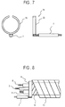
- Fig.7 is a schematic view of connection means for fixing the conductor member and connecting it the conductor wire.
- Fig.8 is a schematic view showing the structure of the wire harness to which the structure shown in Fig.7 is applied.
- Fig.9 is a perspective view showing the structure of the wire harness which has double structure made of the conductor member and the insulator member.
- Fig.10 is a circuit diagram showing the short-circuit detecting circuit using the wire harness with the structure shown in Fig.9.
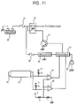
- Fig.11 is a circuit diagram showing an example of an alarm system for ground-short using the wire harness with the structure shown in Fig.9.
- Fig.12 is a flow chart showing the procedure of processing in the alarm system for ground-short using the wire harness with the structure shown in Fig.9.
- Fig.13 is a circuit diagram showing a lighting circuit for an on-board lamp using the wire harness with the function of detection of the short-circuit used in the present invention.
- Fig.14 is a circuit diagram showing the internal construction of a controller shown in Fig.13.
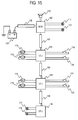
- Fig.15 is a block diagram showing an example in which the wire harness with the function of detection of the short-circuit is applied to a multiplex communication system used in a vehicle (In-vehicle LAN).
- Fig.16 is a flow chart showing the procedure of communication processing in an In-vehicle LAN shown in Fig.15.
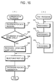
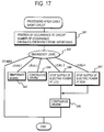
- Fig.17 is a flow chart showing the procedure of processing in a sub-routine of the processing shown in Fig.16 carried out at the time of the cable short-circuit.
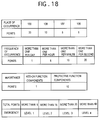
- Fig.18 is a view showing the relationship between points, and place, frequency and importance in the sub-routine of step S41 of Fig.17.
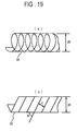
- Fig.19 is an illustration showing an example in which the conductor member for detection of the short-circuit having a resistance value is wound on a cylindrical form.
- Fig.1 shows the structure of a wire harness according to the present invention.
- Electric wires 3, 4 and 5 are covered with an insulating layer, and further covered with an electric conductor member 2 for the detection of short-circuit.
- the wire harness 1 formed by covering the outside of the conductor member with an insulating member 6.
- the insulating member 6 protects the conductor member 2 for the detection of short-circuit and the electric wires 3, 4, 5, and ties them in a bundle.
- the insulating member 6 protects the conductor member 2 from short-circuitting to the ground of a vehicle.
- An electric conductor wire 7 is provided for the connection to an external equipment.
- the wire harness according to this embodiment has the structure substantially identical to a three-core shield wire.
- the electric wires 3, 4, 5 functions as electric conductivity means, and one of three electric wires acts as a electrical communication wire. Further, the conductor member 2 for the detection of short-circuit functions as an electric conductivity layer and the insulating member 6 functions as an electrically insulating layer.
- Fig.2 shows an example of a short-circuit detecting circuit.
- an electric potential is applied through a pull-up resistor R1 to the conductor member 2 for the detection of short-circuit connected to a + (plus) terminal of a comparator 8.
- the voltage divided by resistors R and r is applied to a - (minus) terminal of the comparator 8.
- v V * r / (R + r)
- An output S1 of the comparator 8 indicates a high level when the short-circuit detecting conductor member 2 is at a normal state, or when it is not short-circuited to the ground. While, the output S1 indicates a low level when the conductor member 2 is short-circuited to the ground, for example, due to the damage of the insulating member 6. It is, therefore, possible to detect the short-circuit of the wire harness to the ground by monitoring the output of the comparator 8.
- the pull-up resistor acts as means for applying an electric potential to the electric conductivity layer, and the comparator acts as means for monitoring the electric potential.
- Fig.3 shows another embodiment of the wire harness according to the present invention, which shows in detail a portion of the short-circuit detecting conductor member and the insulating member.
- the insulating member 9 is made of a flexible member such as a vinyl tape, inside of which a conductor member 10 is embeded.
- An adhesive agent 11 in addition to the insulating member 9 and the conductor member 10 forms a tape 12 wound around the wire harness.
- Fig.4 shows the structure of the wire harness in which the tape 12 shown in Fig.3 is wound around the conductor wires 3, 4 and 5.
- the short-circuit detecting circuit has the same construction as that shown in Fig.2.
- the winding of the tape 12 may be overlapped, or may not be overlapped.
- Fig.5 shows a further embodiment of the present invention, which shows the structure of the conductor member for detecting the short-circuit and the insulator member.
- the insulator member 13 is made of a flexible insulating member such as a vinyl tape.
- a conductor member 14 inside of the insulator member 13 is made of a flexible conductivity member such as an alminium tape.
- the electric wires 3, 4, 5 are covered in order by the conductor member 14 and the insulating member 13 thereon. Further, there is no problem even if a different conductor or insulating member is provided between the electric wires 3, 4, 5 and the conductor member 14.
- the short-circuit detecting circuit has the same construction as that shown in Fig.2.
- Fig.6 shows the structure of the conductor member for detecting the short-circuit and insulator member used in a further embodiment of the present invention.
- the insulator member 13 is made of a flexible insulating member such as a vinyl tape.
- the conductor member 14 inside of the insulator member 13 is made of a flexible conductivity member such as an alminium tape.
- the electric wires 16, 17, 18 are covered in order by the conductor member 14 and the insulating member 13 thereon.
- the electric wires 16, 17, 18 is printed on a flexible substrate 19.
- the short-circuit detecting circuit has the same construction as that shown in Fig.2.
- Fig.7 shows connection means for fixing the conductor member 14 and connecting it the conductor wire 7.
- the connection means 15 has such the structure that the conductor wire 7 is connected to a ring-shaped conductor member 20 with a partially cut-away portion 20a.
- Fig.8 shows the construction of the wire harness to which the connection means 15 shown in Fig.7 is applied.
- the connection means15 is made by attaching and swaging the ring-shaped conductor member 20 around the conductor member 14 of the wire harness 1, thereby holding a sufficient connection between the wire harness and the conductor member 20.
- the partially cut-away portion 20a is provided to ensure the margin for swaging.
- the connection provides the conductivity between the conductor member inside the insulating member 13 and the conductor member 20 of the connection means 15. Thereby, the electric potential is applied to the conductor member 14 through the conductor wire 7 connected to the conductor member 20.
- the connection means 15 also act to bind the electric wires 3, 4, 5 and the conductor member 14.
- Fig.9 shows the structure of the wire harness which has double structure made of the conductor member and the insulator member.
- a first insulating member 21 at the outest periphery of the wire harness is used for protecting the whole wire harness. While a first conductor member 22 in the outest periphery is used as means for detecting the ground-short of the wire harness, only alarm is raised even if the conductor member 22 short-circuits, because there are provided a second conductor member 14 and a second insulating member inside the first conductor member.
- a conductor wire 23 is used for applying an electric potential to the first conductor member 22.
- the inside wires 3, 4, 5 may suffer damage in a short time. Therefore, the abnormality is alerted to a driver in another way except the alarm.
- the conductor wire 7 is used for applying an electric potential to the second conductor member 14. While in this example the conductor members and the insulating members are combined double, it is possible to combine them more than double layers.
- Fig.10 shows the short-circuit detecting circuit using the wire harness with the structure shown in Fig.9.
- an electric potential V1 is applied through a pull-up resistor R1 to the first conductor member 22 connected to a + (plus) terminal of a comparator 24.
- the voltage divided by resistors R and r is applied to a - (minus) terminal of the comparator 24.
- An output S1 of the comparator 24 indicates a high level when the first conductor member 22 is at a normal state, or when it is not short-circuited to the ground. While, the output S1 indicates a low level when the first conductor member 22 is short-circuited to the ground, for example, due to the damage of the insulating member of the first conductor member 22.
- an electric potential V2 is applied through a pull-up resistor R2 to the second conductor member 14 connected to a + (plus) terminal of a comparator 25.
- the voltage obtained by dividing the voltage V by resistors R and r is applied to a - (minus) terminal of the comparator 25.
- An output S2 of the comparator 24 indicates the high level when the second conductor member 14 is at a normal state, or when it is not short-circuited to the ground.
- the output S1 indicates the low level when the second conductor member 14 is short-circuited to the ground, for example, due to the damage of the insulating member of the second conductor member 14.
- Fig.11 is a circuit diagram showing an example of an alarm system for ground-short using the double-layer type wire harness with the structure shown in Fig.9.
- a current from the power source is supplied from a - (minus) terminal of the battery through link 31 and emergency cut-off relay 32 to other loads.
- the current from the power source is also supplied through a fuse 34 and a regulator 35 to the control means or a processor 33.
- the short-circuit of the first conductor member 22 is detected by the first comparator 24, and the short-circuit of the second member 14 is detected by the second comparator 25. Outputs of those comparators are input to processor 33.
- the processor 33 processes the outputs according to the procedure shown in Fig.12, and determines the risk of short-circuit.
- Fig.12 is a flow chart showing the procedure of processing in the alarm system for ground-short using the wire harness with the double-layer structure shown in Fig.9.
- step S1 an output of the first comparator (A) 24 is checked, which detects the short-circuit of the first conductor member 22. If the output is at the low level, then the processing advances to step S7.
- step S3 an output of the second comparator (B) 25 is checked, which detects the short-circuit of the second conductor member 14. If the output is at the high level, then it is determined that the wire harness is short-circuited, and a counter B for the detection of the short-circuit of the first conductor member 14 is incremented in step S4.
- step S5 the value of the counter B is compared with the predetermined threshold value N2. If the value of the counter B is equal to or larger than the predetermined threshold value N2, then it is determined that the short-circuit of the second conductor is deteriorated.
- step S6 a main relay 32 for the power source is cut off and the system is shut down. While, if the value of the counter B is smaller than the predetermined threshold value N2, then the process returns to START.
- step S8 the value of the counter (A) is compared with the predetermined threshold value N1 in step S8. In this case, if the value of the counter (A) is equal to or larger than the value N1, then it is determined that the short-circuit of the first conductor 22 is deteriorated. In step S9, a warning flag is stood and the alarm lamp is lighted. If the value of the counter (A) is smaller than the value N1, then the process is returned to START. In step S7, it is checked whether or not the first conductor member 22 is short-circuited. If the first conductor member 22 has already been short-circuited, then the process advances to step S3, and if it has not been short-circuited, then the process returns to START.
- Fig.13 shows a lighting circuit for an on-board lamp using the wire harness with the function of detection of the short-circuit used in the present invention.
- a current from the battery 30 is controlled by a switch 40 and a lamp load 41 is put on or off.
- Wires are connected through connectors 42 and 43.
- Short-circuit detecting conductor members 44, 45, 46, 47 are connected between the battery 30 and the connector 42, between the connector 42 and the controller 48, between the controller 48 and the connector 43, between the connector 43 and the lamp 41, respectively. Namely, the conductor members 44 to 47 are electrically connected to a single controller (control means) 48.
- the alarm is raised by an alarm lamp 49 connected to the controller 48.
- Fig.14 shows the internal construction of the controller shown in Fig.13.
- the controller 48 there are provided comparators 51 to 54 in the controller 48, which check output voltages of the short-circuit detecting conductor members 44 to 47.
- voltages V1 to V4 are applied through pull-up resistors R1 to R4 to + (plus) input terminals of the comparators 51 to 54, respectively.
- An electric potential of the plus input terminal is at the ground when the wire harnesses are short-circuited.
- the voltage obtained by dividing a voltage V by using resistors R and r as shown in the equation (1) is applied to - (minus) input terminal.
- An output of each of the comparators is input to a CPU 55. When the output at the high level is occurred over the predetermined times, it is assumed that the conductor member is short-circuited to the ground. As a result, the alarm lamp is lighted.
- Fig.15 is a block diagram showing an example in which the wire harness with the function of detection of the short-circuit is applied to a multiplex communication system used in a vehicle (hereinafter, referred to as an In-vehicle LAN).
- the In-vehicle LAN comprises one BCM (Body Control Module - control processing unit) 102, a first, a second and a third LCU (Local Control Unit - terminal processing unit) 103, 104, 105, a first, a second and a third combination cable (wire harness) 107, 108, 109, each of which is connected between the processing units, a fourth combination cable 106, and a battery 101 connected through the fourth combination cable 106 to the BCM 102.
- This In-Vehicle LAN system is called as a central control type.
- a buzzer 110 and a first and a second lamp 111, 112 are connected to a BCM 102.
- a power cable (the fourth combination cable) connected between the battery 101 and the control processing unit BCM 102 is constructed as a combination cable of a communication wire and a short-circuit detecting wire harness.
- the first LCU 103 is connected through the first combination cable 107 to the BCM 102.
- the first LCU 103 is also connected to a first and a second motor 113, 114, and a first and a second operating switch 119, 120 each for operating these motors 113, 114.
- the second LCU 104 is connected through the second combination cable 108 to the first LCU 103.
- the second LCU 104 is also connected to a third and a fourth motor 115, 116, and a third and a fourth operating switch 121, 122.
- the third LCU 105 is connected through the first combination cable 109 to the second LCU 104.
- the third LCU 105 is also connected to a third and a fourth lamp 117, 118.
- the BCM 102 transmits and receives data through combination cables to and from the fist LCU 103 and the third LCU 105, and outputs a command signal to control an actuator connected to each of LCUs 103 to 105 on the basis of information obtained from the first, the second, the third LCUs 103, 104, 105 through electrical communication.
- Fig.16 is a flow chart showing the procedure of the whole communication processing.
- the communication processing shown in Fig.16(a) expresses the processing steps in which the BCM 102 communicates with the LCUs 103, 104 and 105, and BGJ (Back Ground Job) shown in Fig.16(b) is the assembly of processing 1 (step S31) to processing n (step S3n) to determine how to control on the basis of the reception data.
- the BGJ processing is endless processing performed when other processing does not performed. For example, if it is required to perform the communication processing when the processing 1 (step S31) is now performing, the communication processing is performed after the communication processing 1 (step S31) is temporarily interrupted, and the processing 1 is performed from the point where the processing 1 is interrupted before.
- the communication processing is reception interruption processing performed when the reception data reaches from the LCUs 103 to 105 to the BCM 102.
- the data from LCUs 103, 104, 105 is first received in step S21. After that, it is checked whether or not the combination cables 106 to 109 are short-circuited in step S22. If it is determined that the short-circuit is occurred in the combination cables, then the processing after the short-circuit of cable is performed in step S23. The next LCU to be accessed is selected in step S24 and the data is transmitted to the selected LCU in step S25. While, if in step S22, it is determined that no short-circuit is occurred, then the next LCU to be accessed is selected in step S24 without performing the processing after the cable short-circuit, and the processing for the data transmission is performed in step S25.
- Fig.17 is a flow chart showing the procedure of processing carried out at the time of the cable short-circuit.
- step S41 the position of occurrence of the short-circuit in the combination cables 106 to 109 is identified.
- the BGM 102 and each of the LCUs 103 to 105 detect the short-circuit of the combination cables 106 to 109, it is possible to detect easily which combination cable is short-circuited.
- the number of occurrence of the short-circuit is detected. Where, the number of occurrence per unit time is expressed as frequency.
- the importance that is, the extent of whether or not the failure caused by the short-circuit extends to safety components such as a head-light, is detected.
- the points are calculated by using a map as shown in Fig.18, and the total points indicate the level of emergency.
- the processing in step S41 indicates the extent of the state of the currently occurred short-circuit.
- levels 1 to 4 are selected according to the calculated level in step S42.
- this processing is temporary alarm processing. If the conditions with respect to the points is satisfied, or the ignition key is turned on, the alarm indicative of them is raised just once. While, When the total points are equal to or more than 15 and less than 20, the processing corresponding to the emergency of level 2 is performed in step S44. This processing is continuous alarm processing. In this case, the alarm is raised continuously or interruptly. Therefore, the alarm is given earlier to a driver. When the total points are equal to or more than 20 and less than 40, the processing corresponding to the emergency of level 3 is performed in step S45.
- step S47 the processing corresponding to the emergency of level 4 is performed in step S47. This processing is performed in such a case that the short-circuit of the combination cable may occur at the position nearer the battery 101. In the level 4, the whole power source in the LAN system is cut off, thereby preventing the occurrence of fire of the short-circuit. When the total points are less than 5, no processing is performed.
- the occurrence of the short-circuit is transmitted to each of the LCUs 103 to 105, at the occurrence of the short-circuit, it is possible to carry out special control processing, for example, the neglect of the data obtained from the position where the cable is cut away and the estimation of the data. Further, Because the LAN system grasps the conditions of operation, it is possible to detect the short-circuit of a wire harness also during driving or parking. Therefore, in the case that the wire harness is short-circuited due to external vibration, it is possible to cut off instantly the power source.
- Fig.19 is an illustration showing an example in which the conductor member 60 for detection of the short-circuit having a resistance value A ( ⁇ / m) is wound on a cylindrical body with radius R.
- Fig.19(a) shows the form of the wounded conductor member
- Fig.19(b) shows the relationship between the angle to be wound and the width of the conductor member. Assumed that the width of the conductor member is d and the conductor member is wound around without gap.
- N R2 /R0 * Vx / (V - Vx) Accordingly, it is possible to determined the position where the ground-short is occurred.
Abstract
Description
- The present invention relates to an apparatus for multiplexing between on-board units of a vehicle by using wire harnesses.
- Recently, various controls in a vehicle are performed by an on-board computer and the associated electrically controlled equipments. Thus, large amounts of electric wiring are used in the vehicle. Those electric wiring such as the wire harnesses have the potential for causing short-circuit. Therefor, various apparatus for detecting the short-circuit of wire harnesses for power supply are proposed in the past.
- One of them is disclosed in Japanese Patent publication No.4-17809 (1992), in which the rated consumption currents for respective loads are calculated in advance, the occurrence of anormality due to the short-circuit is detected by comparing sum of the rated consumption currents with sum of the current one in the vehicle.
- However, when a wire harness is installed into a vehicle body, the harness may be jammed into the vehicle body and/or the coating of the harness may be broken due to the rubbing of the harness on metal portions of the vehicle body. Therefore, a core wire of an electric power source may short to an ground portion of the vehicle body, and thus serious accidents such as the fire of the vehicle may break out in the worst case.
- In the above prior art, it is constructed such that the serious accidents can be prevented immediately by cutting off the whole current. Therefore, when such the accidents occurs during driving, a power source is cut off. As a result, the vehicle stops suddenly. Further, when the driver changes the load of an electric system, it is required to change the predetermined rated value. Therefore, there was a possibility that a malfunction occurs. In addition, while the short-circuit of the wire harness can be detected, the processing after the detection of the short-circuit can not be performed.
- An object of the present invention is to provide an apparatus for multiplexing between on-board units of a vehicle, which can detect at an early stage the short-circuit of the wire harness.
- Another object of the present invention is to provide an apparatus for multiplexing between on-board units of a vehicle, which can perform a suitable processing when the short-circuit of the wire harness is detected, thereby the serious accident can be prevented in advance.
- In order to achieve the above objects, an electric conductivity layer is provided outside electric wires, and the predetermined electric potential is provided to the electric conductivity layer. Further, the outside of the electric conductivity layer is covered with a insulator layer. As a result, a sub-wire harness is formed as a whole. The wire harness in the whole vehicle is constructed by connecting the sub-wire harnesses to each other by a connector. The multiplexing apparatus includes besides monitor means for monitoring an electric potential of the wire harness and detecting a short-circuit to the ground, control means for determining the short-circuit on the basis of the result of the detection by the monitoring means, alarm raising means for raising alarm according to a command from the control means, and a circuit breaker for break the current from a power source.
- According to one aspect of the present invention, the multiplexing apparatus multiplexes between processing units and a battery unit of a vehicle which are connected to one another by wire harnesses, by grouping a variety of on-board controlled objects into a plurality of neighboring controlled objects and controlling each of the groups by respective processing units. The wire harness has electric conductors of which the outer peripheral portion are covered with a first insulating layer, electric conductivity layer which covers the electric conductors, a second insulating layer which covers the peripheral portion of the electric conductivity layer, means for applying an electric potential to said electric conductivity layer, and means for monitoring the electric potential of said electric conductivity layer.
- Preferably, the electric conductivity layer is formed by a thin mesh wire.
- The multiplexing apparatus according to the present invention further may include alarm means for raising alarm to a driver, and control means for starting up said alarm means to raise the alarm.
- In addition to the alarm means and the control means, the multiplexing apparatus further may include a power source circuit breaker for cutting off a current supplied from the battery unit, wherein said control means start up said power source circuit breaker to cut off the current from the battery, when said electric conductivity layer is short-circuited to the ground.
- In the multiplexing apparatus according to the present invention, there may be provided a plurality of electric conductivity layers between which insulating layer are sandwitched alternately,
- Preferably, the multiplexing apparatus further may include alarm means for raising alarm to a driver, a power source circuit breaker for cutting off a current supplied from the battery unit, and control means for starting up said alarm means to raise alarm and starting up said power source circuit breaker to cut off the current from the battery unit, when at least one of said electric conductivity layers is short-circuited to the ground.
- Preferably, the multiplexing apparatus further include means for applying an electric potential to said electric conductivity layer, means for monitoring the electric potential of said electric conductivity layer between respective groups, means for detecting the short-circuit of the wire harness to the ground on the basis of the output of said monitoring means, and circuit breaker for cutting off a current passing through said electric conductor from the power source when the short-circuit of the wire harness to the ground is detected by said detecting means.
- The above multiplexing apparatus further may include data storing means for storing the data used to estimate the damage by using at least one of the frequency of the short-circuit of the wire harness to the ground, the term of time of the short-circuit, the position of the short-circuit and the importance as parameters, and control means for setting the condition of cut-off of the circuit breaker on the basis of the data stored in the data storing means.
- Preferably, the multiplexing apparatus according to the present invention further includes means for applying an electric potential to said electric conductivity layer, means for monitoring the electric potential of said electric conductivity layer between respective processing units, means for detecting the short-circuit of the wire harness to the ground on the basis of the output of said monitoring means, and alarm means for raising alarm to a driver when the short-circuit of the wire harness to the ground is detected by said detecting means.
- In the multiplexing apparatus described above, the electric potential applying means preferably include a C-shaped electric conductivity body a portion of which is notched, an electric conductor connected to the electric conductivity body, for detecting an electric potential, and a pull-up resistor, and wherein said electric conductivity body is press-bonded to the electric conductor from the outside of the electric conductivity layer of the thin mesh wire.
- It is desirable to provide data storing means for storing the data used to estimate the damage by using at least one of the frequency of the short-circuit of the wire harness to the ground, the term of time of the short-circuit, the position of the short-circuit and the importance as parameters, and control means for changing a alarm level of the alarm means on the basis of the data stored in the data storing means.
- Further, the power source cutting-off means preferably include a switching element.
- The multiplexing apparatus according to the present invention further may include a fail-safe means which allow the processing unit in charge of the group of the area where abnormality occurred to notify the occurrence of the abnormality to processing unit of another group when said wire harness becomes abnormal, cut away the abnormal area and leave the control to the processing unit of another group.
- Preferably, in the multiplexing apparatus according to the present invention, the processing units include a terminal processing unit which performs only the processing at the associated group, and a control unit which performs all the processing including the processing of the terminal processing unit.
- In operation, the outest insulating layer of the wire harness functions as a protecting layer, and it prevents the power source line from the ground-short. When the insulating layer is broken and it reaches the electric conductivity layer, the electric potential of the electric conductivity layer changes. Therefore, it is possible to determine the presence or absence of the short-circuit by detecting the change. When the short-circuit is detected, it become possible to perform the predetermined processing by the processing unit in charge of the group to which the short-circuited wire harness belongs. Because the electric conductivity layer is formed by a thin mesh wire, there is not almost the fear of disconnection due to external force. It is, therefore, possible to maintain the stable performance.
- More concretely, the control means start up the alarm means when the electric conductivity layer is short-circuited to the ground, and thus alarm is raised. As a result, it is possible to give an attention to a driver.
- Further, the control means start up the power source circuit breaker when the electric conductivity layer is short-circuited to the ground, and thus a current from the power source is cut off. As a result, it is possible to prevent vehicle's fire due to the short-circuit.
- Furthermore, because a plurality of electric conductivity layers are provided for the detection of short-circuit, the control means determine whether only alarm is raised or the power source is also cut off in addition of the alarm. Therefore, it is possible to take the suitable counter-measure according to the position where the short-circuit occurs.
- Further, monitoring means monitor the electric potential applied to the conductivity layer, and the detecting means detect the short-circuit of the wire harness to the ground on the basis of an output of the monitoring means. When the detecting means detect the ground-short, the circuit breaker cuts off the power source. At that time, the control means grasp the state of the ground-short from data to estimate damage by using the parameters of the frequency of the short-circuit of the wire harness to the ground, the term of time of the short-circuit, the position of the short-circuit and the importance, and set the condition for the cut-off of the power source. Therefore, it is possible to take the most suitable counter-measure in accordance with the state of the ground-short.
- Further, monitoring means monitor the electric potential applied to the conductivity layer, and the detecting means detect the short-circuit of the wire harness to the ground on the basis of an output of the monitoring means. When the detecting means detect the ground-short, the alarm means raise alarm. At that time, the control means grasp the state of the ground-short from data to estimate damage by using the parameters of the frequency of the short-circuit of the wire harness to the ground, the term of time of the short-circuit, the position of the short-circuit and the importance, and change the level to raise alarm so as to raise the most suitable alarm in accordance with the state of the ground-short.
- When the abnormality conditions such as the ground-short occurs, the processing unit in charge of the group of the area where the abnormality occurred notify the occurrence of the abnormality to processing unit of another group, and cut away the abnormal area to keep safety. At that time, because the control which has been performing by the processing unit in charge is left to the processing unit of another group, the effect due to the cut-away of the abnormal area is effectively suppressed.
- The multiplexing apparatus includes a terminal processing unit which performs only the processing at the associated group, and a control processing unit which performs all the processing including the processing of the terminal processing unit.
- In the drawings, like reference numerals denote like parts in the various views.
- Fig.1 is a perspective view showing the configuration of a wire harness used in an embodiment of the present invention.
- Fig.2 is a circuit diagram showing a short-circuit detecting circuit using the wire harness shown in Fig.1.
- Fig.3 is a perspective view showing a tape formed by a conductor member for detecting the short-circuit and an insulator member used in another embodiment of the present invention.
- Fig.4 is a perspective view showing the structure of the wire harness in which the tape shown in Fig.3 is wound around electric conductor wires.
- Fig.5 is a view showing the structure of the conductor member for detecting the short-circuit and insulator member used in a further embodiment of the present invention.
- Fig.6 is a view showing the structure of the conductor member for detecting the short-circuit and insulator member used in a further embodiment of the present invention.
- Fig.7 is a schematic view of connection means for fixing the conductor member and connecting it the conductor wire.
- Fig.8 is a schematic view showing the structure of the wire harness to which the structure shown in Fig.7 is applied.
- Fig.9 is a perspective view showing the structure of the wire harness which has double structure made of the conductor member and the insulator member.
- Fig.10 is a circuit diagram showing the short-circuit detecting circuit using the wire harness with the structure shown in Fig.9.
- Fig.11 is a circuit diagram showing an example of an alarm system for ground-short using the wire harness with the structure shown in Fig.9.
- Fig.12 is a flow chart showing the procedure of processing in the alarm system for ground-short using the wire harness with the structure shown in Fig.9.
- Fig.13 is a circuit diagram showing a lighting circuit for an on-board lamp using the wire harness with the function of detection of the short-circuit used in the present invention.
- Fig.14 is a circuit diagram showing the internal construction of a controller shown in Fig.13.
- Fig.15 is a block diagram showing an example in which the wire harness with the function of detection of the short-circuit is applied to a multiplex communication system used in a vehicle (In-vehicle LAN).
- Fig.16 is a flow chart showing the procedure of communication processing in an In-vehicle LAN shown in Fig.15.
- Fig.17 is a flow chart showing the procedure of processing in a sub-routine of the processing shown in Fig.16 carried out at the time of the cable short-circuit.
- Fig.18 is a view showing the relationship between points, and place, frequency and importance in the sub-routine of step S41 of Fig.17.
- Fig.19 is an illustration showing an example in which the conductor member for detection of the short-circuit having a resistance value is wound on a cylindrical form.
- Embodiments of the present invention will be explained hereinafter with reference to the drawings.
- Fig.1 shows the structure of a wire harness according to the present invention.
Electric wires electric conductor member 2 for the detection of short-circuit. Thewire harness 1 formed by covering the outside of the conductor member with an insulatingmember 6. The insulatingmember 6 protects theconductor member 2 for the detection of short-circuit and theelectric wires member 6 protects theconductor member 2 from short-circuitting to the ground of a vehicle. Anelectric conductor wire 7 is provided for the connection to an external equipment. The wire harness according to this embodiment has the structure substantially identical to a three-core shield wire. Therefore, in this embodiment, theelectric wires conductor member 2 for the detection of short-circuit functions as an electric conductivity layer and the insulatingmember 6 functions as an electrically insulating layer. - Fig.2 shows an example of a short-circuit detecting circuit. In Fig.2, an electric potential is applied through a pull-up resistor R1 to the
conductor member 2 for the detection of short-circuit connected to a + (plus) terminal of acomparator 8. The voltage divided by resistors R and r is applied to a - (minus) terminal of thecomparator 8.
- An output S1 of the
comparator 8 indicates a high level when the short-circuit detectingconductor member 2 is at a normal state, or when it is not short-circuited to the ground. While, the output S1 indicates a low level when theconductor member 2 is short-circuited to the ground, for example, due to the damage of the insulatingmember 6. It is, therefore, possible to detect the short-circuit of the wire harness to the ground by monitoring the output of thecomparator 8. In this embodiment, the pull-up resistor acts as means for applying an electric potential to the electric conductivity layer, and the comparator acts as means for monitoring the electric potential. - Fig.3 shows another embodiment of the wire harness according to the present invention, which shows in detail a portion of the short-circuit detecting conductor member and the insulating member. The insulating
member 9 is made of a flexible member such as a vinyl tape, inside of which aconductor member 10 is embeded. Anadhesive agent 11 in addition to the insulatingmember 9 and theconductor member 10 forms atape 12 wound around the wire harness. By forming in such a way, it becomes easy to detect the short-circuit, because the electric potential of theconductor member 10 drops to the ground potential when the ground-short is occurred by the breakage due to the rubbing of the insulatingmember 9. - Fig.4 shows the structure of the wire harness in which the
tape 12 shown in Fig.3 is wound around theconductor wires tape 12 may be overlapped, or may not be overlapped. - Fig.5 shows a further embodiment of the present invention, which shows the structure of the conductor member for detecting the short-circuit and the insulator member. In Fig.5, the
insulator member 13 is made of a flexible insulating member such as a vinyl tape. Aconductor member 14 inside of theinsulator member 13 is made of a flexible conductivity member such as an alminium tape. Theelectric wires conductor member 14 and the insulatingmember 13 thereon. Further, there is no problem even if a different conductor or insulating member is provided between theelectric wires conductor member 14. The short-circuit detecting circuit has the same construction as that shown in Fig.2. - Fig.6 shows the structure of the conductor member for detecting the short-circuit and insulator member used in a further embodiment of the present invention. In Fig.6, the
insulator member 13 is made of a flexible insulating member such as a vinyl tape. Theconductor member 14 inside of theinsulator member 13 is made of a flexible conductivity member such as an alminium tape. Theelectric wires conductor member 14 and the insulatingmember 13 thereon. In this embodiment, theelectric wires flexible substrate 19. The short-circuit detecting circuit has the same construction as that shown in Fig.2. - Fig.7 shows connection means for fixing the
conductor member 14 and connecting it theconductor wire 7. As understood from Fig.7, the connection means 15 has such the structure that theconductor wire 7 is connected to a ring-shapedconductor member 20 with a partially cut-away portion 20a. - Fig.8 shows the construction of the wire harness to which the connection means 15 shown in Fig.7 is applied. In Fig.8, the connection means15 is made by attaching and swaging the ring-shaped
conductor member 20 around theconductor member 14 of thewire harness 1, thereby holding a sufficient connection between the wire harness and theconductor member 20. The partially cut-away portion 20a is provided to ensure the margin for swaging. The connection provides the conductivity between the conductor member inside the insulatingmember 13 and theconductor member 20 of the connection means 15. Thereby, the electric potential is applied to theconductor member 14 through theconductor wire 7 connected to theconductor member 20. Further, the connection means 15 also act to bind theelectric wires conductor member 14. - Fig.9 shows the structure of the wire harness which has double structure made of the conductor member and the insulator member. A first insulating
member 21 at the outest periphery of the wire harness is used for protecting the whole wire harness. While afirst conductor member 22 in the outest periphery is used as means for detecting the ground-short of the wire harness, only alarm is raised even if theconductor member 22 short-circuits, because there are provided asecond conductor member 14 and a second insulating member inside the first conductor member. Aconductor wire 23 is used for applying an electric potential to thefirst conductor member 22. If the second insulatingmember 13 suffers damage after the damage of thefirst conductor member 22, and thesecond conductor member 14 short-circuits to the ground, theinside wires conductor wire 7 is used for applying an electric potential to thesecond conductor member 14. While in this example the conductor members and the insulating members are combined double, it is possible to combine them more than double layers. - Fig.10 shows the short-circuit detecting circuit using the wire harness with the structure shown in Fig.9. In Fig.10, an electric potential V1 is applied through a pull-up resistor R1 to the
first conductor member 22 connected to a + (plus) terminal of acomparator 24. As described with respect to the equation (1), the voltage divided by resistors R and r is applied to a - (minus) terminal of thecomparator 24. An output S1 of thecomparator 24 indicates a high level when thefirst conductor member 22 is at a normal state, or when it is not short-circuited to the ground. While, the output S1 indicates a low level when thefirst conductor member 22 is short-circuited to the ground, for example, due to the damage of the insulating member of thefirst conductor member 22. - Further, an electric potential V2 is applied through a pull-up resistor R2 to the
second conductor member 14 connected to a + (plus) terminal of acomparator 25. As described with respect to the equation (1), the voltage obtained by dividing the voltage V by resistors R and r is applied to a - (minus) terminal of thecomparator 25. An output S2 of thecomparator 24 indicates the high level when thesecond conductor member 14 is at a normal state, or when it is not short-circuited to the ground. While, the output S1 indicates the low level when thesecond conductor member 14 is short-circuited to the ground, for example, due to the damage of the insulating member of thesecond conductor member 14. - It is, therefore, possible to detect the ground-short of the wire harness including its risk by monitoring the outputs of the
comparators - Fig.11 is a circuit diagram showing an example of an alarm system for ground-short using the double-layer type wire harness with the structure shown in Fig.9. In Fig.11, a current from the power source is supplied from a - (minus) terminal of the battery through
link 31 and emergency cut-off relay 32 to other loads. The current from the power source is also supplied through afuse 34 and aregulator 35 to the control means or aprocessor 33. The short-circuit of thefirst conductor member 22 is detected by thefirst comparator 24, and the short-circuit of thesecond member 14 is detected by thesecond comparator 25. Outputs of those comparators are input toprocessor 33. Theprocessor 33 processes the outputs according to the procedure shown in Fig.12, and determines the risk of short-circuit. Namely, when thefirst conductor member 22 is short-circuited, a alarm lamp is lighted and caution is given to a driver. When thesecond conductor member 14 is short-circuited, it is determined that the wire harness will become dangerous, and adriver 37 is cut off and thus arelay 32 is cut off. As a result, the whole power of a vehicle is cut off. - Referring now to Fig.12, Fig.12 is a flow chart showing the procedure of processing in the alarm system for ground-short using the wire harness with the double-layer structure shown in Fig.9. In step S1, an output of the first comparator (A) 24 is checked, which detects the short-circuit of the
first conductor member 22. If the output is at the low level, then the processing advances to step S7. In step S3, an output of the second comparator (B) 25 is checked, which detects the short-circuit of thesecond conductor member 14. If the output is at the high level, then it is determined that the wire harness is short-circuited, and a counter B for the detection of the short-circuit of thefirst conductor member 14 is incremented in step S4. If the output is at the low level, then the process advances to step S5. In step S5, the value of the counter B is compared with the predetermined threshold value N2. If the value of the counter B is equal to or larger than the predetermined threshold value N2, then it is determined that the short-circuit of the second conductor is deteriorated. In step S6, amain relay 32 for the power source is cut off and the system is shut down. While, if the value of the counter B is smaller than the predetermined threshold value N2, then the process returns to START. - Further, if the output of the second comparater (B) is at the low level in step S3, then the value of the counter (A) is compared with the predetermined threshold value N1 in step S8. In this case, if the value of the counter (A) is equal to or larger than the value N1, then it is determined that the short-circuit of the
first conductor 22 is deteriorated. In step S9, a warning flag is stood and the alarm lamp is lighted. If the value of the counter (A) is smaller than the value N1, then the process is returned to START. In step S7, it is checked whether or not thefirst conductor member 22 is short-circuited. If thefirst conductor member 22 has already been short-circuited, then the process advances to step S3, and if it has not been short-circuited, then the process returns to START. - Fig.13 shows a lighting circuit for an on-board lamp using the wire harness with the function of detection of the short-circuit used in the present invention. A current from the
battery 30 is controlled by aswitch 40 and alamp load 41 is put on or off. Wires are connected throughconnectors conductor members battery 30 and theconnector 42, between theconnector 42 and thecontroller 48, between thecontroller 48 and theconnector 43, between theconnector 43 and thelamp 41, respectively. Namely, theconductor members 44 to 47 are electrically connected to a single controller (control means) 48. When each of the short-circuit detecting conductor member is short-circuited over the predetermined times, the alarm is raised by analarm lamp 49 connected to thecontroller 48. - Fig.14 shows the internal construction of the controller shown in Fig.13. In the
controller 48, there are providedcomparators 51 to 54 in thecontroller 48, which check output voltages of the short-circuit detectingconductor members 44 to 47. When the wire harnesses are not short-circuited, voltages V1 to V4 are applied through pull-up resistors R1 to R4 to + (plus) input terminals of thecomparators 51 to 54, respectively. An electric potential of the plus input terminal is at the ground when the wire harnesses are short-circuited. While, the voltage obtained by dividing a voltage V by using resistors R and r as shown in the equation (1) is applied to - (minus) input terminal. An output of each of the comparators is input to aCPU 55. When the output at the high level is occurred over the predetermined times, it is assumed that the conductor member is short-circuited to the ground. As a result, the alarm lamp is lighted. - Fig.15 is a block diagram showing an example in which the wire harness with the function of detection of the short-circuit is applied to a multiplex communication system used in a vehicle (hereinafter, referred to as an In-vehicle LAN). The In-vehicle LAN comprises one BCM (Body Control Module - control processing unit) 102, a first, a second and a third LCU (Local Control Unit - terminal processing unit) 103, 104, 105, a first, a second and a third combination cable (wire harness) 107, 108, 109, each of which is connected between the processing units, a
fourth combination cable 106, and abattery 101 connected through thefourth combination cable 106 to theBCM 102. This In-Vehicle LAN system is called as a central control type. - A
buzzer 110 and a first and asecond lamp BCM 102. A power cable (the fourth combination cable) connected between thebattery 101 and the controlprocessing unit BCM 102 is constructed as a combination cable of a communication wire and a short-circuit detecting wire harness. - The
first LCU 103 is connected through thefirst combination cable 107 to theBCM 102. Thefirst LCU 103 is also connected to a first and asecond motor second operating switch motors second LCU 104 is connected through thesecond combination cable 108 to thefirst LCU 103. Thesecond LCU 104 is also connected to a third and afourth motor fourth operating switch third LCU 105 is connected through thefirst combination cable 109 to thesecond LCU 104. Thethird LCU 105 is also connected to a third and afourth lamp - The
BCM 102 transmits and receives data through combination cables to and from thefist LCU 103 and thethird LCU 105, and outputs a command signal to control an actuator connected to each ofLCUs 103 to 105 on the basis of information obtained from the first, the second, thethird LCUs - There are provided the first to the fourth operation switches 119 to 122, the
buzzer 110, the first to thefourth lamps fourth motors 113 to 116 in the neighborhood of a plurality of electric equipments in the system. They are connected to any one of the first to thethird LCU 103 to 105 and theBCU 102. Further, the short-circuit detecting circuits or thecombination cables 106 to 109 is incorporated in the BCU and theLCUs 103 to 105. TheBCM 102 detects the short-circuit of the fourth combination cable, thefirst LCU 103 the first combination cable, thesecond LCU 104 the second combination cable, and thethird LCU 105 the third combination cable. - A brief explanation of a series of data transmission will be given next. When the
BCM 102 transmits a certain data to an LCU, the LCU which received the data answers the input data itself back to the BCU. Therefore, first, a data transmission signal directed from theBCU 102 to any one of theLCU 103 to 105 appears in a communication wire of the combination cable, and then a data reception signal directed from any one of theLCU 103 to 105 to theBCM 102 appears in the same communication wire. A set of the transmission and reception signals as described above are supplied to other LUCs in the same way. The data answered to theLCU 103 to 105 is input to a self-contained load control unit, and operates actuators such as the saidmotors 113 to 116. Further, signals indicative of the state ofvarious operating switches 119 to 122 is answered to theBCM 102, which theLCUs 103 to 105 input. these signals indicate operation to be required. - Fig.16 is a flow chart showing the procedure of the whole communication processing. The communication processing shown in Fig.16(a) expresses the processing steps in which the
BCM 102 communicates with theLCUs processing 1 is performed from the point where theprocessing 1 is interrupted before. - The communication processing is reception interruption processing performed when the reception data reaches from the
LCUs 103 to 105 to theBCM 102. In this processing, the data fromLCUs combination cables 106 to 109 are short-circuited in step S22. If it is determined that the short-circuit is occurred in the combination cables, then the processing after the short-circuit of cable is performed in step S23. The next LCU to be accessed is selected in step S24 and the data is transmitted to the selected LCU in step S25. While, if in step S22, it is determined that no short-circuit is occurred, then the next LCU to be accessed is selected in step S24 without performing the processing after the cable short-circuit, and the processing for the data transmission is performed in step S25. - Fig.17 is a flow chart showing the procedure of processing carried out at the time of the cable short-circuit. In step S41, the position of occurrence of the short-circuit in the
combination cables 106 to 109 is identified. As described above, because theBGM 102 and each of theLCUs 103 to 105 detect the short-circuit of thecombination cables 106 to 109, it is possible to detect easily which combination cable is short-circuited. After the short-circuit of the combination cables is detected, the number of occurrence of the short-circuit is detected. Where, the number of occurrence per unit time is expressed as frequency. Next, the importance, that is, the extent of whether or not the failure caused by the short-circuit extends to safety components such as a head-light, is detected. These detected data are used as parameters in the calculation of points. The points are calculated by using a map as shown in Fig.18, and the total points indicate the level of emergency. In other words, the processing in step S41 indicates the extent of the state of the currently occurred short-circuit. - When the emergency level is calculated as described above,
levels 1 to 4 are selected according to the calculated level in step S42. this processing is temporary alarm processing. If the conditions with respect to the points is satisfied, or the ignition key is turned on, the alarm indicative of them is raised just once. While, When the total points are equal to or more than 15 and less than 20, the processing corresponding to the emergency oflevel 2 is performed in step S44. This processing is continuous alarm processing. In this case, the alarm is raised continuously or interruptly. Therefore, the alarm is given earlier to a driver. When the total points are equal to or more than 20 and less than 40, the processing corresponding to the emergency oflevel 3 is performed in step S45. In this processing , a current from the power source to the downstream is cut off at theLCUs 103 to 105 upstream of the position where the short-circuit of the combination cable is occurred, and the continuous alarm is raised instep 46 in a way similar to that ofStep 44. Because the current from the power source is cut off at the position of occurrence of the short-circuit, it becomes possible to prevent the worst condition which causes vehicle fire even if the short-circuit is deteriorated, and raise confirmly an alarm to a driver. Next, When the total points are equal to or more than 40, the processing corresponding to the emergency oflevel 4 is performed in step S47. This processing is performed in such a case that the short-circuit of the combination cable may occur at the position nearer thebattery 101. In thelevel 4, the whole power source in the LAN system is cut off, thereby preventing the occurrence of fire of the short-circuit. When the total points are less than 5, no processing is performed. - By performing the processing described above, it is possible to alert a driver with the occurrence of short-circuit and further repair, and prevent the occurrence of the vehicle fire in advance because the power source is cut off in the case that the short-circuit occurs frequently. It should be appreciated that it is possible to cut away only the cable at the position where the short-circuit is occurred such that the electric power can be supplied from another circuit by using looped combination cable. Further, the position where the short-circuit occurs can be easily known through the LAN communication. Furthermore, because the occurrence of the short-circuit is transmitted to each of the
LCUs 103 to 105, at the occurrence of the short-circuit, it is possible to carry out special control processing, for example, the neglect of the data obtained from the position where the cable is cut away and the estimation of the data. Further, Because the LAN system grasps the conditions of operation, it is possible to detect the short-circuit of a wire harness also during driving or parking. Therefore, in the case that the wire harness is short-circuited due to external vibration, it is possible to cut off instantly the power source. - Fig.19 is an illustration showing an example in which the
conductor member 60 for detection of the short-circuit having a resistance value A ( Ω / m) is wound on a cylindrical body with radius R. Fig.19(a) shows the form of the wounded conductor member, and Fig.19(b) shows the relationship between the angle to be wound and the width of the conductor member. Assumed that the width of the conductor member is d and the conductor member is wound around without gap.


- The determination of the position where the ground-short is occurred is calculated by measuring the Vx and obtaining the N. Namely,

Claims (14)
- An apparatus for multiplexing between processing units and a battery unit of a vehicle which are connected to one another by wire harnesses, by grouping a variety of controlled on-board objects into a plurality of neighboring controlled objects and controlling each of the groups by respective processing units, in which said wire harness comprises;
electric conductors of which the outer peripheral portion are covered with a first insulating layer,
electric conductivity layer which covers said electric conductors,
a second insulating layer which covers the outer peripheral portion of said electric conductivity layer,
means for applying an electric potential to said electric conductivity layer, and
means for monitoring the electric potential of said electric conductivity layer. - A multiplexing apparatus according to claim 1, wherein said electric conductivity layer is formed by a thin mesh wire.
- A multiplexing apparatus according to claim 1, further comprising alarm means for raising alarm to a driver, and control means for starting up said alarm means to raise the alarm.
- A multiplexing apparatus according to claim 3, further comprising a power source circuit breaker for cutting off a current supplied from the battery unit, wherein said control means start up said power source circuit breaker to cut off the current from the battery, when said electric conductivity layer is short-circuited to the ground.
- A multiplexing apparatus according to claim 1, wherein there are provided a plurality of electric conductivity layers between which insulating layer are sandwitched alternately,
- A multiplexing apparatus according to claim 5, further comprising;
alarm means for raising alarm to a driver, a power source circuit breaker for cutting off a current supplied from the battery unit, and
control means for starting up said alarm means to raise alarm and starting up said power source circuit breaker to cut off the current from the battery unit, when at least one of said electric conductivity layers is short-circuited to the ground. - A multiplexing apparatus according to claim 1, further comprising;
means for applying an electric potential to said electric conductivity layer,
means for monitoring the electric potential of said electric conductivity layer between respective groups,
means for detecting the short-circuit of the wire harness to the ground on the basis of the output of said monitoring means, and
circuit breaker for cutting off a current passing through said electric conductor from the power source when the short-circuit of the wire harness to the ground is detected by said detecting means. - A multiplexing apparatus according to claim 7, further comprising;
data storing means for storing the data used to estimate damages by using at least one of the frequency of the short-circuit of the wire harness to the ground, the term of time of the short-circuit, the position of the short-circuit and the importance as parameters, and
control means for setting the condition of cut-off of the circuit breaker on the basis of the data stored in the data storing means. - A multiplexing apparatus according to claim 1, further comprising;
means for applying an electric potential to said electric conductivity layer,
means for monitoring the electric potential of said electric conductivity layer between respective processing units,
means for detecting the short-circuit of the wire harness to the ground on the basis of the output of said monitoring means, and
alarm means for raising alarm to a driver when the short-circuit of the wire harness to the ground is detected by said detecting means. - A multiplexing apparatus according to claim 7, wherein said electric potential applying means comprise a C-shaped electric conductivity body a portion of which is notched, an electric conductor connected to the electric conductivity body, for detecting an electric potential, and a pull-up resistor, and wherein said electric conductivity body is press-bonded to the electric conductor from the outside of the electric conductivity layer of the thin mesh wire.
- A multiplexing apparatus according to claim 9, further comprising;
data storing means for storing the data used to estimate the damage by using at least one of the frequency of the short-circuit of the wire harness to the ground, the term of time of the short-circuit, the position of the short-circuit and the importance as parameters, and
control means for changing a alarm level of the alarm means on the basis of the data stored in the data storing means. - A multiplexing apparatus according to claim 4, wherein said power source cutting-off means include a switching element.
- A multiplexing apparatus according to claim 1, further comprising a fail-safe means which allow the processing unit in charge of the group of the area where abnormality occurred to notify the occurrence of the abnormality to processing unit of another group when said wire harness becomes abnormal, cut away the abnormal area and leave the control to the processing unit of another group.
- A multiplexing apparatus according to claim 1, wherein said processing units include a terminal processing unit which performs only the processing at the associated group, and a control unit which performs all the processing including the processing of the terminal processing units.
Applications Claiming Priority (3)
| Application Number | Priority Date | Filing Date | Title |
|---|---|---|---|
| JP3264795 | 1995-02-21 | ||
| JP3264795 | 1995-02-21 | ||
| JP32647/95 | 1995-02-21 |
Publications (3)
| Publication Number | Publication Date |
|---|---|
| EP0728622A2 true EP0728622A2 (en) | 1996-08-28 |
| EP0728622A3 EP0728622A3 (en) | 1999-03-31 |
| EP0728622B1 EP0728622B1 (en) | 2005-11-30 |
Family
ID=12364655
Family Applications (1)
| Application Number | Title | Priority Date | Filing Date |
|---|---|---|---|
| EP96102576A Expired - Lifetime EP0728622B1 (en) | 1995-02-21 | 1996-02-21 | Apparatus for multiplexing between units in a vehicle |
Country Status (4)
| Country | Link |
|---|---|
| US (2) | US6020811A (en) |
| EP (1) | EP0728622B1 (en) |
| KR (1) | KR960031206A (en) |
| DE (1) | DE69635502T2 (en) |
Cited By (7)
| Publication number | Priority date | Publication date | Assignee | Title |
|---|---|---|---|---|
| DE10000551C1 (en) * | 2000-01-08 | 2001-07-05 | Bayerische Motoren Werke Ag | Device for monitoring a battery cable |
| DE10017455A1 (en) * | 2000-04-07 | 2001-10-18 | Audi Ag | Protection device for current cable in automobile has breaker between current source and cable operated by signal from cable damage sensor |
| DE10132752A1 (en) * | 2001-07-10 | 2003-05-15 | Daimler Chrysler Ag | Method and device for protecting a conductor when an arc occurs |
| EP1385177A1 (en) * | 2002-07-23 | 2004-01-28 | Alcoa Fujikura Gesellschaft mit beschränkter Haftung | Circuit arrangement for electrical network on board a vehicle |
| DE19725153B4 (en) * | 1996-06-13 | 2004-04-08 | Hitachi, Ltd. | Device for monitoring the power supply |
| DE19826028B4 (en) * | 1997-06-10 | 2004-11-18 | Hitachi, Ltd. | Device for monitoring a cable used in a vehicle |
| EP3536561A1 (en) * | 2018-03-07 | 2019-09-11 | Yazaki Corporation | Circuit body for vehicle |
Families Citing this family (20)
| Publication number | Priority date | Publication date | Assignee | Title |
|---|---|---|---|---|
| JP3043274B2 (en) * | 1996-04-23 | 2000-05-22 | 株式会社ハーネス総合技術研究所 | In-vehicle electronic control unit |
| US6104302A (en) * | 1999-08-12 | 2000-08-15 | Sloan Valve Company | Fuse protected power supply circuit for a sensor-operated solenoid |
| US8266465B2 (en) | 2000-07-26 | 2012-09-11 | Bridgestone Americas Tire Operation, LLC | System for conserving battery life in a battery operated device |
| US7161476B2 (en) | 2000-07-26 | 2007-01-09 | Bridgestone Firestone North American Tire, Llc | Electronic tire management system |
| DE10193456T1 (en) * | 2000-08-18 | 2002-10-24 | Mitsubishi Electric Corp | Shielded wire, method of manufacturing a shielded wire, and lighting device for a discharge lamp using the shielded wire |
| JP2002074568A (en) * | 2000-08-30 | 2002-03-15 | Nittan Co Ltd | Disaster prevention system and terminal device |
| US6980546B2 (en) * | 2001-09-17 | 2005-12-27 | The Boeing Company | Broadband internet protocol telephony system |
| JP2006189782A (en) * | 2004-12-06 | 2006-07-20 | Fujitsu Ten Ltd | Display device |
| JP4596259B2 (en) * | 2005-08-30 | 2010-12-08 | 株式会社デンソー | In-vehicle electronic equipment wiring reconfiguration system |
| JP4614085B2 (en) * | 2005-08-30 | 2011-01-19 | 株式会社デンソー | In-vehicle electronic device connection system |
| US7358443B2 (en) * | 2005-09-21 | 2008-04-15 | Tower Manufacturing | Braided cord with conductive foil |
| FR2922714B1 (en) * | 2007-10-19 | 2010-03-12 | Valeo Vision | ELECTRICAL SUPPLY DEVICE FOR A DISCHARGE LAMP COMPRISING A BALLAST SHIELD AND A BEAM SHIELD CONNECTED IN PARLLELE TO A COMMON POTENTIAL |
| US8164433B2 (en) * | 2009-04-17 | 2012-04-24 | Ac Propulsion, Inc. | Detecting faults in a wiring harness |
| JP5541331B2 (en) | 2012-04-20 | 2014-07-09 | 日立金属株式会社 | Composite harness |
| DE102014018642B4 (en) | 2014-12-13 | 2021-07-08 | Audi Ag | EMC measure and short circuit detection in the motor vehicle |
| CN106654140A (en) * | 2016-10-08 | 2017-05-10 | 郑州宇通客车股份有限公司 | Sampling wire, sampling wire harness, battery management system and automobile |
| JP7094670B2 (en) * | 2017-07-03 | 2022-07-04 | 矢崎総業株式会社 | Setting device and computer |
| JP7283467B2 (en) * | 2018-03-27 | 2023-05-30 | 株式会社Gsユアサ | Diagnostic device, power storage device, diagnostic method |
| JP7287017B2 (en) | 2019-03-14 | 2023-06-06 | 株式会社デンソー | Mobile power supply system |
| JP7266057B2 (en) * | 2021-03-24 | 2023-04-27 | 本田技研工業株式会社 | vehicle |
Citations (3)
| Publication number | Priority date | Publication date | Assignee | Title |
|---|---|---|---|---|
| EP0029406A1 (en) * | 1979-11-09 | 1981-05-27 | Siemens Aktiengesellschaft | Flexible electrical connection cord with protection device |
| DE8906828U1 (en) * | 1989-06-03 | 1990-07-05 | Felten & Guilleaume Energietechnik Ag, 5000 Koeln, De | |
| GB2277618A (en) * | 1993-04-28 | 1994-11-02 | Henlys Group Plc | Multiplexed data transmission for motor vehicle |
Family Cites Families (4)
| Publication number | Priority date | Publication date | Assignee | Title |
|---|---|---|---|---|
| US2787784A (en) * | 1954-04-30 | 1957-04-02 | Harold T Meryman | Triboelectric detecting system |
| US4859989A (en) * | 1987-12-01 | 1989-08-22 | W. L. Gore & Associates, Inc. | Security system and signal carrying member thereof |
| JP2654843B2 (en) * | 1990-05-10 | 1997-09-17 | 株式会社ダイフク | Shelf with slide table |
| US5534848A (en) * | 1994-05-19 | 1996-07-09 | General Motors Corporation | Automotive fault tolerant serial communication |
-
1996
- 1996-02-16 KR KR1019960003833A patent/KR960031206A/en not_active Application Discontinuation
- 1996-02-21 DE DE69635502T patent/DE69635502T2/en not_active Expired - Fee Related
- 1996-02-21 EP EP96102576A patent/EP0728622B1/en not_active Expired - Lifetime
- 1996-02-21 US US08/604,613 patent/US6020811A/en not_active Expired - Fee Related
-
1999
- 1999-06-04 US US09/325,648 patent/US6243018B1/en not_active Expired - Fee Related
Patent Citations (3)
| Publication number | Priority date | Publication date | Assignee | Title |
|---|---|---|---|---|
| EP0029406A1 (en) * | 1979-11-09 | 1981-05-27 | Siemens Aktiengesellschaft | Flexible electrical connection cord with protection device |
| DE8906828U1 (en) * | 1989-06-03 | 1990-07-05 | Felten & Guilleaume Energietechnik Ag, 5000 Koeln, De | |
| GB2277618A (en) * | 1993-04-28 | 1994-11-02 | Henlys Group Plc | Multiplexed data transmission for motor vehicle |
Cited By (11)
| Publication number | Priority date | Publication date | Assignee | Title |
|---|---|---|---|---|
| DE19725153B4 (en) * | 1996-06-13 | 2004-04-08 | Hitachi, Ltd. | Device for monitoring the power supply |
| DE19826028B4 (en) * | 1997-06-10 | 2004-11-18 | Hitachi, Ltd. | Device for monitoring a cable used in a vehicle |
| DE10000551C1 (en) * | 2000-01-08 | 2001-07-05 | Bayerische Motoren Werke Ag | Device for monitoring a battery cable |
| EP1114752A2 (en) | 2000-01-08 | 2001-07-11 | Bayerische Motoren Werke Aktiengesellschaft | Device for monitoring a battery lead |
| EP1114752A3 (en) * | 2000-01-08 | 2005-05-11 | Bayerische Motoren Werke Aktiengesellschaft | Device for monitoring a battery lead |
| DE10017455A1 (en) * | 2000-04-07 | 2001-10-18 | Audi Ag | Protection device for current cable in automobile has breaker between current source and cable operated by signal from cable damage sensor |
| DE10017455C2 (en) * | 2000-04-07 | 2003-01-23 | Audi Ag | Protection device for a power cable in a motor vehicle |
| DE10132752A1 (en) * | 2001-07-10 | 2003-05-15 | Daimler Chrysler Ag | Method and device for protecting a conductor when an arc occurs |
| DE10132752B4 (en) * | 2001-07-10 | 2005-08-25 | Daimlerchrysler Ag | Method and device for protecting a conductor when an arc occurs |
| EP1385177A1 (en) * | 2002-07-23 | 2004-01-28 | Alcoa Fujikura Gesellschaft mit beschränkter Haftung | Circuit arrangement for electrical network on board a vehicle |
| EP3536561A1 (en) * | 2018-03-07 | 2019-09-11 | Yazaki Corporation | Circuit body for vehicle |
Also Published As
| Publication number | Publication date |
|---|---|
| DE69635502D1 (en) | 2006-01-05 |
| KR960031206A (en) | 1996-09-17 |
| DE69635502T2 (en) | 2006-07-20 |
| US6243018B1 (en) | 2001-06-05 |
| EP0728622A3 (en) | 1999-03-31 |
| US6020811A (en) | 2000-02-01 |
| EP0728622B1 (en) | 2005-11-30 |
Similar Documents
| Publication | Publication Date | Title |
|---|---|---|
| US6020811A (en) | Apparatus for multiplexing between on-board units in a vehicle | |
| US6169337B1 (en) | Power supplying apparatus for a vehicle and an intensive wiring apparatus | |
| EP1645475B1 (en) | Power supply apparatus for vehicle | |
| CN109689436B (en) | Automobile electrical system and automobile with same | |
| US6166453A (en) | Apparatus for driving electrical loads provided at a vehicle | |
| JP3949406B2 (en) | Electrical connection device for vehicle | |
| US20090015976A1 (en) | Power feed system for vehicle | |
| JP3644792B2 (en) | Vehicle power supply device | |
| US20220185209A1 (en) | Power network for a motor vehicle and method for operating a power network for a motor vehicle | |
| JPH09312937A (en) | Vehicle power supply distribution apparatus | |
| JPH10341524A (en) | Signal transmitter for mounting on vehicle, and signal transmission method, and power supply controller for mounting on vehicle, and power method, and cable abnormality detector for mounting on vehicle | |
| JP2000016199A (en) | Electric power feeding device for automobile | |
| JPH1084629A (en) | Power distribution system | |
| JP6533699B2 (en) | Energization control device, electrification control method and disconnection detection device | |
| JP3310876B2 (en) | Power supply control device | |
| JP2001119960A (en) | Method and device for urgently interrupting vehicle feeder circuit and vehicle voltage converter | |
| JP3734918B2 (en) | Power distribution device for vehicles | |
| JP3500672B2 (en) | Wire harness | |
| AU2018415357A1 (en) | Vehicle electrical starter circuit protection | |
| JP3554568B2 (en) | Control device for internal combustion engine | |
| JP7447350B2 (en) | vehicle control system | |
| SE524576C2 (en) | ADR unit | |
| JP2004203091A (en) | Feeder system for vehicle | |
| JP2003205799A (en) | On-vehicle electric power source system | |
| JPH07141921A (en) | Wire harness |
Legal Events
| Date | Code | Title | Description |
|---|---|---|---|
| PUAI | Public reference made under article 153(3) epc to a published international application that has entered the european phase |
Free format text: ORIGINAL CODE: 0009012 |
|
| 17P | Request for examination filed |
Effective date: 19960221 |
|
| AK | Designated contracting states |
Kind code of ref document: A2 Designated state(s): DE FR GB |
|
| PUAL | Search report despatched |
Free format text: ORIGINAL CODE: 0009013 |
|
| AK | Designated contracting states |
Kind code of ref document: A3 Designated state(s): DE FR GB |
|
| 17Q | First examination report despatched |
Effective date: 20021011 |
|
| GRAP | Despatch of communication of intention to grant a patent |
Free format text: ORIGINAL CODE: EPIDOSNIGR1 |
|
| GRAS | Grant fee paid |
Free format text: ORIGINAL CODE: EPIDOSNIGR3 |
|
| GRAA | (expected) grant |
Free format text: ORIGINAL CODE: 0009210 |
|
| AK | Designated contracting states |
Kind code of ref document: B1 Designated state(s): DE FR GB |
|
| REG | Reference to a national code |
Ref country code: GB Ref legal event code: FG4D |
|
| REF | Corresponds to: |
Ref document number: 69635502 Country of ref document: DE Date of ref document: 20060105 Kind code of ref document: P |
|
| PG25 | Lapsed in a contracting state [announced via postgrant information from national office to epo] |
Ref country code: GB Free format text: LAPSE BECAUSE OF NON-PAYMENT OF DUE FEES Effective date: 20060228 |
|
| PLBE | No opposition filed within time limit |
Free format text: ORIGINAL CODE: 0009261 |
|
| STAA | Information on the status of an ep patent application or granted ep patent |
Free format text: STATUS: NO OPPOSITION FILED WITHIN TIME LIMIT |
|
| GBPC | Gb: european patent ceased through non-payment of renewal fee |
Effective date: 20060228 |
|
| 26N | No opposition filed |
Effective date: 20060831 |
|
| EN | Fr: translation not filed | ||
| PG25 | Lapsed in a contracting state [announced via postgrant information from national office to epo] |
Ref country code: FR Free format text: LAPSE BECAUSE OF FAILURE TO SUBMIT A TRANSLATION OF THE DESCRIPTION OR TO PAY THE FEE WITHIN THE PRESCRIBED TIME-LIMIT Effective date: 20070119 |
|
| PGFP | Annual fee paid to national office [announced via postgrant information from national office to epo] |
Ref country code: DE Payment date: 20080307 Year of fee payment: 13 |
|
| PG25 | Lapsed in a contracting state [announced via postgrant information from national office to epo] |
Ref country code: FR Free format text: LAPSE BECAUSE OF FAILURE TO SUBMIT A TRANSLATION OF THE DESCRIPTION OR TO PAY THE FEE WITHIN THE PRESCRIBED TIME-LIMIT Effective date: 20060228 |
|
| PG25 | Lapsed in a contracting state [announced via postgrant information from national office to epo] |
Ref country code: FR Free format text: LAPSE BECAUSE OF FAILURE TO SUBMIT A TRANSLATION OF THE DESCRIPTION OR TO PAY THE FEE WITHIN THE PRESCRIBED TIME-LIMIT Effective date: 20051130 |
|
| PG25 | Lapsed in a contracting state [announced via postgrant information from national office to epo] |
Ref country code: DE Free format text: LAPSE BECAUSE OF NON-PAYMENT OF DUE FEES Effective date: 20090901 |