EP1384832A2 - Sichtschutzeinrichtung - Google Patents
Sichtschutzeinrichtung Download PDFInfo
- Publication number
- EP1384832A2 EP1384832A2 EP03013918A EP03013918A EP1384832A2 EP 1384832 A2 EP1384832 A2 EP 1384832A2 EP 03013918 A EP03013918 A EP 03013918A EP 03013918 A EP03013918 A EP 03013918A EP 1384832 A2 EP1384832 A2 EP 1384832A2
- Authority
- EP
- European Patent Office
- Prior art keywords
- frame
- wing
- brackets
- frame legs
- frame leg
- Prior art date
- Legal status (The legal status is an assumption and is not a legal conclusion. Google has not performed a legal analysis and makes no representation as to the accuracy of the status listed.)
- Granted
Links
Images


Classifications
-
- A—HUMAN NECESSITIES
- A47—FURNITURE; DOMESTIC ARTICLES OR APPLIANCES; COFFEE MILLS; SPICE MILLS; SUCTION CLEANERS IN GENERAL
- A47G—HOUSEHOLD OR TABLE EQUIPMENT
- A47G5/00—Screens; Draught-deflectors
-
- E—FIXED CONSTRUCTIONS
- E04—BUILDING
- E04B—GENERAL BUILDING CONSTRUCTIONS; WALLS, e.g. PARTITIONS; ROOFS; FLOORS; CEILINGS; INSULATION OR OTHER PROTECTION OF BUILDINGS
- E04B2/00—Walls, e.g. partitions, for buildings; Wall construction with regard to insulation; Connections specially adapted to walls
- E04B2/74—Removable non-load-bearing partitions; Partitions with a free upper edge
- E04B2/7407—Removable non-load-bearing partitions; Partitions with a free upper edge assembled using frames with infill panels or coverings only; made-up of panels and a support structure incorporating posts
- E04B2/7416—Removable non-load-bearing partitions; Partitions with a free upper edge assembled using frames with infill panels or coverings only; made-up of panels and a support structure incorporating posts with free upper edge, e.g. for use as office space dividers
- E04B2/7422—Removable non-load-bearing partitions; Partitions with a free upper edge assembled using frames with infill panels or coverings only; made-up of panels and a support structure incorporating posts with free upper edge, e.g. for use as office space dividers with separate framed panels without intermediary support posts
- E04B2/7427—Removable non-load-bearing partitions; Partitions with a free upper edge assembled using frames with infill panels or coverings only; made-up of panels and a support structure incorporating posts with free upper edge, e.g. for use as office space dividers with separate framed panels without intermediary support posts with adjustable angular connection of panels
- E04B2/7431—Removable non-load-bearing partitions; Partitions with a free upper edge assembled using frames with infill panels or coverings only; made-up of panels and a support structure incorporating posts with free upper edge, e.g. for use as office space dividers with separate framed panels without intermediary support posts with adjustable angular connection of panels using hinges having two parallel rotation axes
-
- E—FIXED CONSTRUCTIONS
- E04—BUILDING
- E04B—GENERAL BUILDING CONSTRUCTIONS; WALLS, e.g. PARTITIONS; ROOFS; FLOORS; CEILINGS; INSULATION OR OTHER PROTECTION OF BUILDINGS
- E04B2/00—Walls, e.g. partitions, for buildings; Wall construction with regard to insulation; Connections specially adapted to walls
- E04B2/74—Removable non-load-bearing partitions; Partitions with a free upper edge
- E04B2002/7479—Details of connection of flexible sheets to frame or posts
-
- F—MECHANICAL ENGINEERING; LIGHTING; HEATING; WEAPONS; BLASTING
- F16—ENGINEERING ELEMENTS AND UNITS; GENERAL MEASURES FOR PRODUCING AND MAINTAINING EFFECTIVE FUNCTIONING OF MACHINES OR INSTALLATIONS; THERMAL INSULATION IN GENERAL
- F16B—DEVICES FOR FASTENING OR SECURING CONSTRUCTIONAL ELEMENTS OR MACHINE PARTS TOGETHER, e.g. NAILS, BOLTS, CIRCLIPS, CLAMPS, CLIPS OR WEDGES; JOINTS OR JOINTING
- F16B7/00—Connections of rods or tubes, e.g. of non-circular section, mutually, including resilient connections
- F16B7/04—Clamping or clipping connections
- F16B7/0433—Clamping or clipping connections for rods or tubes being in parallel relationship
Definitions
- the invention relates to a sight protection device.
- Screening devices are in the form of fixed stands so-called screens or Spanish walls for the division known from interiors. These screens are mainly used the subdivision of open plan offices and are considered heavy, too sound-absorbing constructions known. For outdoors are sight or wind protection elements as light fabric constructions known, the cloth between by means of cords and ground anchors tensioned tent poles is stretched. Such light Privacy screens are only for temporary use intended. These are not suitable for installation Terraces and balconies.
- the invention is therefore based on the object of a visual protection device to create the relatively easy and is simply constructed, but is for permanent assembly suitable for patios and balconies.
- a sight protection device comprehensively at least two pivotally connected Sashes as frames with privacy screens, of which two frame legs extending approximately parallel to each other neighboring wing over each with the concerned Frame legs a hinge brackets together are connected, the brackets each having at least one A frame leg in at least one angular position Form locking.
- Such a device according to the invention can be wall-mounted or also be provided for floor installation.
- a hinge brackets make it easy to put together different frame wings.
- the Clamp at least partially positively with the frame legs the wing interact, easy alignment the wings of a sight protection device achieve each other.
- the brackets preferably each form two approximately C-shaped trained receptacles for the frame legs, which in assembled Location embrace this.
- the clips are expediently made in one piece from plastic educated.
- the brackets can at least in the area of a receptacle have a locking recess, with locking projections the frame legs work together so that the individual wings the sight protection device in at least one predetermined Angular position to each other can be determined. Additionally or alternatively the brackets can be designed so that at least provide a recording with swivel limit stops is that cooperate with the locking projections of the frame legs.
- Privacy protection device is provided that at least a frame leg of at least one wing two each Locking projections at the same height, diametrically opposite each other are arranged. In this way you can at least some of the brackets in two offset by 90 ° to each other Lock angular positions with respect to the frame legs. This makes it possible to set up several wings like an accordion with contours aligned fold and align them in a line arranged to move out.
- the frames of the wings are expediently made up of several Tubes or rods forming frame legs,
- the individual elements are preferably each with an end widened sleeve ends and each with tapered ends Provide plug ends.
- the pipe ends can also be secured one inside the other using spring buttons his.
- the pipe ends are preferably screwed together, the screw heads and / or nuts each as Can serve locking elements.
- the frames can have corner elements, for example which the frame legs are put together. These corner elements can, for example, as injection molded plastic components be executed.
- Brackets can be attached to the wall on at least one wing be provided, each provided with fasteners Base and an approximately C-shaped, the frame leg have enclosing recording. Over the wall mount several wings can be bent relative to each other simply on a house wall or a terrace boundary wall assemble, so that the whole arrangement Can be locked on the brackets permanently mounted on the wall or can be clipped.
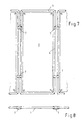
- Screening device essentially a plurality of wings 1 which are pivotally connected to one another, each provided with a screen covering 2 Frame 3 are formed.
- the frames are each made up of individual the frame legs 10 forming tube sections 4 assembled.
- the pipe sections 4 can have different diameters have, so that their pluggability is guaranteed is, as shown in the figures. alternative this can be the ends of at least some pipe sections 4 each be widened at the ends like a sleeve, so that the Form the pipe ends of the receptacle and plug ends.
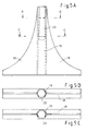
- the pipe sections 4 joined together to form a frame 3 are each in the area of their mutual penetration with Screws 5 connected.
- the corners 6 of the frame 3 are also with fasteners 6 for holding and tensioning the privacy screen covering 2 provided.
- the fasteners 6 are only hinted at. These can come in many different ways Way, for example as screws, Bolts, tension wires or the like.
- the corners of the frame also as one-piece corner elements made by injection molding be formed, each with receptacles for the pipe sections 4 are provided.
- connecting clips 7 are made of plastic trained and have two diametrically opposite arranged, approximately C-shaped snap receptacles 8.
- the snap shots 8 are each elastic by four trained holding arms 9 of the connecting clips 7 are formed.
- the The spring elasticity of these results from the properties and the thickness distribution of the thermoplastic material.
- wing 1 of the sight protection device on both sides with connecting clips 7 on an adjacent wing 1 attached.
- the connecting clips 7 allow the frame legs 10 neighboring frames 3 simply together clipping, while simultaneously pivoting articulation the same is guaranteed.
- Each forms a frame leg 10 of a wing 1, the pivot axis about which the Pivotal movement of the adjacent wing 1 is carried out.
- a frame leg 10 is locked in rotation in the connecting clip 7, namely by locking projections 11, which in corresponding Engage locking recesses 12 of the holding arms 9.
- the locking tabs 11 can in the simplest case through the heads of cylinder screws are formed by the respective pipe section 4 are performed.
- each Swing limit stops 17 are provided, each with at the same height of the frame legs 10 diametrically opposite Arranged locking projections 11 in the sense of a lock of connection clip 7 and frame leg 10 cooperate with each other.
- the connection clip 7 in question snapped onto the frame leg 10 that the heads of the Pipe sections 4 connecting cylinder screw between insert two holding arms 9 arranged one above the other and rest there against the swivel limit stops 17. hereby is not just a radial fixation of the connecting clip 7 and frame legs 10 causes each other, but also an axial securing of the same.
- the connecting clips 7 are each in the area of a snapshot 8, at least in the illustrated embodiment, provided with a recess 12, each in Deepest of the C-shaped snap receptacle 8 arranged is.
- the locking recess 12 is offset by 90 ° to the opposite arranged pivot limit stops 17 positioned, so that the connecting clips 7 in two by 90 ° angular distance Positions staggered to each other can be defined are. To do this, remove the relevant connection clip 7 of the frame leg 10 required.
- the locking projections 11 are of course shown in the Constellation at a height of the frame leg in question 11 arranged. This can be in the area, for example an already necessary screwing of the pipe sections 4 be with each other.
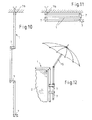
- the wing shown in Figures 2 and 5 1 of the privacy screen is for floor installation with two Clip feet 14 provided.
- the clip feet 14 are also with a Snapshot provided, which is designed so that this each on a vertically extending frame leg 10 of a wing 1 are laterally attachable and in the upright position Position each lower, each horizontally extending Support frame legs 10 in the area of a corner.
- the clip feet 14 are for this purpose as one-piece plastic elements with a base area 18 and one piece molded standpipe 19 provided.
- the standpipe 19 has the Forming a snapshot, an approximately C-shaped cross-sectional profile, and only over a partial length that is based on the vertical Frame leg 10 of a frame 3 is snapped on.
- the receiving slot extending in the longitudinal direction of the standpipe 19 20 expands towards the base area 18 of the foot clip 14. In this area the Receiving slot 20 a kind of blind hole in which the lower frame corner or the lower frame leg 10 of the frame 3 rests.
- Wall clips 7b are for wall mounting the screen provided, which also form a snap receptacle 8 and the relevant frame leg of the to be mounted on the wall 13 Grasp wing 1.
- the formation of the wall clips 7b is approximately according to the design of the connecting clips 7th
- the wall clips 7b are each provided with a base that interspersed with a screw against the wall 13.
- the clip technology provided in accordance with the invention allows also various accessories and conversion parts of the privacy screen attach, as shown for example in Figure 12.
- With 16 is shown in Figure 6, a ground spike with a snap, the a set-up of the sight protection device on a soft surface allows.
Landscapes
- Engineering & Computer Science (AREA)
- Architecture (AREA)
- Physics & Mathematics (AREA)
- Electromagnetism (AREA)
- Civil Engineering (AREA)
- Structural Engineering (AREA)
- Clamps And Clips (AREA)
- Aiming, Guidance, Guns With A Light Source, Armor, Camouflage, And Targets (AREA)
- Buffer Packaging (AREA)
- Curtains And Furnishings For Windows Or Doors (AREA)
- Mirrors, Picture Frames, Photograph Stands, And Related Fastening Devices (AREA)
- Non-Silver Salt Photosensitive Materials And Non-Silver Salt Photography (AREA)
- Eye Examination Apparatus (AREA)
- Noodles (AREA)
Abstract
Description
- Figur 1
- eine perspektivische Ansicht eines Flügels der Sichtschutzeinrichtung gemäß der Erfindung,
- Figur 2
- eine Ansicht eines solchen Flügels, der mit Fußelementen versehen ist,
- Figur 3
- eine vergrößerte Ansicht des in Figur 2 mit III gekennzeichneten Bereichs,
- Figur 4
- eine Ansicht eines Fußelements,
- Figur 5
- eine Draufsicht auf den in Figur 2 dargestellten Flügel,
- Figur 5a
- eine Ansicht des als Klippfuß ausgebildeten Fußelements,
- Figur 5b
- einen Schnitt durch das Standrohr des Klippfußes entlang der Linien B-B,
- Figur 5c
- einen Schnitt durch das Standrohr des Klippfußes entlang der Linien C-C,
- Figur 6
- eine Ansicht eines Erdspießes mit Aufnahme für den Rahmenschenkel eines Flügels,
- Figur 7
- eine Ansicht, die die Verbindung mehrerer Flügel mittels als Verbindungsklipps ausgebildeten Haltern veranschaulicht,
- Figur 8
- eine Draufsicht auf die in Figur 7 dargestellte Anordnung,
- Figur 9
- eine schematische Darstellung eines Verbindungsklipps und dessen Verbindung mit dem Rahmenschenkel eines Flügels,
- Figur 9a
- eine Ansicht des Verbindungsklipps in Richtung des in Figur 9 dargestellten Pfeils A
- Figur 9b
- einen Schnitt durch das Rahmenrohr im Bereich der Rastvorsprünge, wobei die Lage des Rahmenrohrs in Bezug auf den in Figur 9c dargestellten Verbindungsklipp dargestellt ist,
- Figuren 9c 9f
- schematische Darstellungen, die das Zusammenwirken von Verbindungsklipp und Rahmenschekel verdeutlichen,
- Figuren 10 und 11
- eine Darstellung der Sichtschutzeinrichtung gemäß der Erfindung zur Wandmontage in ausgezogener und eingeklappter Stellung und
- Figur 12
- eine Ansicht eines Flügels der Sichtschutzeinrichtung gemäß der Erfindung mit einem daran befestigten Sonnenschirm.
- 1
- Flügel
- 2
- Sichtschutzbespannung
- 3
- Rahmen
- 4
- Rohrabschnitte
- 5
- Schrauben
- 6
- Befestigungsmittel
- 7
- Verbindungsklipp
- 7b
- Wandklipp
- 8
- Schnappaufnahmen
- 9
- Haltearme
- 10
- Rahmenschenkel
- 11
- Rastvorsprünge
- 12
- Rastvertiefungen
- 13
- Wand
- 14
- Fußklipp
- 15
- Sonnenschirm
- 16
- Erdspieß
- 17
- Schwenkbegrenzungsanschläge
- 18
- Sockelbereich
- 19
- Standrohr
- 20
- Aufnahmeschlitz
Claims (11)
- Sichtschutzeinrichtung, umfassend wenigstens zwei schwenkbeweglich miteinander verbundene Flügel (1) als jeweils mit Sichtschutzbespannung (2) versehene Rahmen (3), von denen zwei sich etwa parallel zueinander erstreckende Rahmenschenkel (10) benachbarter Flügel (1) über jeweils mit dem betreffenden Rahmenschenkel (10) ein Scharnier bildende Klammern miteinander verbunden sind, wobei die Klammern jeweils mit wenigstens einem Rahmenschenkel (10) in wenigstens einer Winkelstellung eine formschlüssige Arretierung bilden.
- Einrichtung nach Anspruch 1, dadurch gekennzeichnet , dass die Klammern jeweils zwei etwa C-förmig ausgebildete Aufnahmen (8) für die Rahmenschenkel (10) aufweisen, die in montierter Lage diese umgreifen.
- Einrichtung nach Anspruch 1 oder 2, dadurch gekennzeichnet , dass die Schnappaufnahmen (8) jeweils durch federelastisch ausgebildete Halterarme (9) gebildet werden.
- Einrichtung nach einem der Ansprüche 1 bis 3, dadurch gekennzeichnet, dass die Klammern einstückig aus Kunststoff ausgebildet sind.
- Einrichtung nach Anspruch 3, dadurch gekennzeichnet , dass die Klammern wenigstens im Bereich einer Schnappaufnahme (8) mindestens eine Rastvertiefung (12) aufweisen, die mit Rastvorsprüngen (11) der Rahmenschenkel (10) zusammenwirken.
- Einrichtung nach einem der Ansprüche 3 oder 5, dadurch gekennzeichnet, dass wenigstens eine Schnappaufnahme (8) mit Schwenkbegrenzungsanschlägen (17) versehen ist, die mit den Rastvorsprüngen (11) eines Rahmenschenkels (10) zusammenwirken.
- Einrichtung nach Anspruch 5 oder 6, dadurch gekennzeichnet , dass an wenigstens einem Rahmenschenkel (10) wenigstens eines Flügels (1) jeweils zwei Rastvorsprünge (11) auf gleicher Höhe jeweils paarweise diametral gegenüberliegend angeordnet sind.
- Einrichtung nach Anspruch 7, dadurch gekennzeichnet, dass die Rahmen (3) Eckelemente aufweisen, über welche die Rahmenschenkel (10) zusammengefügt sind.
- Einrichtung nach einem der Ansprüche 1 bis 8, dadurch gekennzeichnet, dass die Rahmen (3) der Flügel (1) aus mehreren die Rahmenschenkel (10) bildenden Rohren oder Stangen zusammengesetzt ist.
- Einrichtung nach einem der Ansprüche 1 bis 7, dadurch gekennzeichnet, dass an wenigstens einem Flügel (1) Klammern (7b) zur Wandbefestigung vorgesehen sind, die jeweils einen mit Befestigungsmitteln versehenen Sockel und eine etwa C-förmig ausgebildete, den Rahmenschenkel (10) umschließende Schnappaufnahme (8) aufweisen.
- Sichtschutzeinrichtung, umfassend wenigstens einen Flügel (1) als mit Sichtschutzbespannung (2) versehener Rahmen (3), der mittels ein Scharnier bildenden Klammer an einer Wand befestigbar ist.
Priority Applications (1)
| Application Number | Priority Date | Filing Date | Title |
|---|---|---|---|
| EP08018439.3A EP2014844B9 (de) | 2002-07-22 | 2003-06-20 | Sichtschutzeinrichtung |
Applications Claiming Priority (2)
| Application Number | Priority Date | Filing Date | Title |
|---|---|---|---|
| DE20211079U DE20211079U1 (de) | 2002-07-22 | 2002-07-22 | Sichtschutzeinrichtung |
| DE20211079U | 2002-07-22 |
Related Child Applications (1)
| Application Number | Title | Priority Date | Filing Date |
|---|---|---|---|
| EP08018439.3A Division EP2014844B9 (de) | 2002-07-22 | 2003-06-20 | Sichtschutzeinrichtung |
Publications (3)
| Publication Number | Publication Date |
|---|---|
| EP1384832A2 true EP1384832A2 (de) | 2004-01-28 |
| EP1384832A3 EP1384832A3 (de) | 2004-11-17 |
| EP1384832B1 EP1384832B1 (de) | 2009-05-20 |
Family
ID=7973273
Family Applications (2)
| Application Number | Title | Priority Date | Filing Date |
|---|---|---|---|
| EP08018439.3A Expired - Lifetime EP2014844B9 (de) | 2002-07-22 | 2003-06-20 | Sichtschutzeinrichtung |
| EP03013918A Expired - Lifetime EP1384832B1 (de) | 2002-07-22 | 2003-06-20 | Sichtschutzeinrichtung |
Family Applications Before (1)
| Application Number | Title | Priority Date | Filing Date |
|---|---|---|---|
| EP08018439.3A Expired - Lifetime EP2014844B9 (de) | 2002-07-22 | 2003-06-20 | Sichtschutzeinrichtung |
Country Status (4)
| Country | Link |
|---|---|
| EP (2) | EP2014844B9 (de) |
| AT (1) | ATE431880T1 (de) |
| DE (2) | DE20211079U1 (de) |
| ES (1) | ES2327400T3 (de) |
Cited By (3)
| Publication number | Priority date | Publication date | Assignee | Title |
|---|---|---|---|---|
| EP2000616A2 (de) | 2007-06-06 | 2008-12-10 | Peddy Shield Sonnenschutzsysteme GmbH | Erdspieß mit angeschraubtem Rohr als Aufstellvariante Clip-Paravent |
| DE202011102324U1 (de) | 2011-06-20 | 2011-11-10 | Peddy Shield Sonnenschutzsysteme Gmbh | Sichtschutz- und/oder Windschutzeinrichtung |
| CN112726826A (zh) * | 2019-10-28 | 2021-04-30 | 佛山市南海区品位智能家具有限公司 | 一种足球阳光房及其安装方法 |
Families Citing this family (4)
| Publication number | Priority date | Publication date | Assignee | Title |
|---|---|---|---|---|
| WO2012007897A1 (en) * | 2010-07-12 | 2012-01-19 | Necdet Suat Mehmetoglu | Folding balcony screen |
| FR3022576B1 (fr) * | 2014-06-20 | 2016-07-01 | Creations Mathou Jean-Pierre | Barriere a panneaux repliables |
| DE202015103524U1 (de) | 2015-07-03 | 2016-10-13 | M.A.C.'s Holding Gmbh | Paravent |
| CN113616053B (zh) * | 2021-07-28 | 2022-08-19 | 南通市第一人民医院 | 一种重症监护室用具有负压功能的防感染隔帘 |
Family Cites Families (5)
| Publication number | Priority date | Publication date | Assignee | Title |
|---|---|---|---|---|
| US4134439A (en) * | 1977-06-22 | 1979-01-16 | Commercial Vehicle Parts, Inc. | Portable industrial screen |
| DE3509683A1 (de) * | 1985-03-18 | 1986-09-18 | Jürgen-Peter 2902 Rastede Sudmann | Duschabtrennung |
| US4774792A (en) * | 1986-08-25 | 1988-10-04 | Ballance Design Limited | Exhibition display apparatus |
| US5722477A (en) | 1995-10-31 | 1998-03-03 | The Children's Factory | Pipe connector assembly with internal locking mechanism |
| US6206079B1 (en) * | 1998-11-30 | 2001-03-27 | Industrial Noise Control, Inc. | Curtain barrier assembly |
-
2002
- 2002-07-22 DE DE20211079U patent/DE20211079U1/de not_active Expired - Lifetime
-
2003
- 2003-06-20 EP EP08018439.3A patent/EP2014844B9/de not_active Expired - Lifetime
- 2003-06-20 DE DE50311530T patent/DE50311530D1/de not_active Expired - Lifetime
- 2003-06-20 EP EP03013918A patent/EP1384832B1/de not_active Expired - Lifetime
- 2003-06-20 AT AT03013918T patent/ATE431880T1/de active
- 2003-06-20 ES ES03013918T patent/ES2327400T3/es not_active Expired - Lifetime
Cited By (4)
| Publication number | Priority date | Publication date | Assignee | Title |
|---|---|---|---|---|
| EP2000616A2 (de) | 2007-06-06 | 2008-12-10 | Peddy Shield Sonnenschutzsysteme GmbH | Erdspieß mit angeschraubtem Rohr als Aufstellvariante Clip-Paravent |
| EP2000616A3 (de) * | 2007-06-06 | 2011-03-23 | Peddy Shield Sonnenschutzsysteme GmbH | Erdspieß mit angeschraubtem Rohr als Aufstellvariante Clip-Paravent |
| DE202011102324U1 (de) | 2011-06-20 | 2011-11-10 | Peddy Shield Sonnenschutzsysteme Gmbh | Sichtschutz- und/oder Windschutzeinrichtung |
| CN112726826A (zh) * | 2019-10-28 | 2021-04-30 | 佛山市南海区品位智能家具有限公司 | 一种足球阳光房及其安装方法 |
Also Published As
| Publication number | Publication date |
|---|---|
| EP2014844A1 (de) | 2009-01-14 |
| ATE431880T1 (de) | 2009-06-15 |
| DE50311530D1 (de) | 2009-07-02 |
| EP2014844B1 (de) | 2013-04-03 |
| DE20211079U1 (de) | 2002-09-26 |
| EP2014844B9 (de) | 2013-07-03 |
| EP1384832A3 (de) | 2004-11-17 |
| EP1384832B1 (de) | 2009-05-20 |
| ES2327400T3 (es) | 2009-10-29 |
Similar Documents
| Publication | Publication Date | Title |
|---|---|---|
| DE10338816B3 (de) | Halterung für eine Platte, insbesondere für eine Glasscheibe | |
| AT513685B1 (de) | Rahmensystem für ein Insekten- und/oder Pollenschutzgitter | |
| DE202004000706U1 (de) | Profilschienensystem zur Überprüfung von Bodenbelagsübergängen | |
| EP2014844B1 (de) | Sichtschutzeinrichtung | |
| EP1168949A1 (de) | Befestigungselement mit variablem hub | |
| DE102020100493A1 (de) | Torpfosten für Sichtschutz | |
| DE10163807A1 (de) | Befestigungsvorrichtung | |
| DE4403827A1 (de) | Bauelementesatz für eine Einfriedung, Verblendung oder Vertäfelung | |
| AT13216U1 (de) | Wandkonstruktion für den Garten- und Landschaftsbau | |
| DE102010049782A1 (de) | Rahmensystem für ein Schutzgitter | |
| DE3401427A1 (de) | Tuerpuffer | |
| EP3985201B1 (de) | Markise, insbesondere wintergarten- oder wetterschutzmarkise, mit einem stützträger | |
| EP1541776B1 (de) | Befestigungsprofil | |
| DE102016213394B4 (de) | Schutzvorrichtung, insbesondere als Insektenschutz | |
| EP0617191B1 (de) | Führungsschienenanordnung für eine Wintergartenmarkise o. dgl. | |
| DE19503263B4 (de) | Markise | |
| DE19818357A1 (de) | Befestigungssatz für einen Querriegel eines Zaunes oder dergleichen | |
| CH626416A5 (en) | Wall structure for use in cubicles, in particular sanitary cubicles | |
| DE10156283B4 (de) | Deckelplatte, insbesondere für Omnibusse und umlaufendes Profil | |
| DE202016101899U1 (de) | Variable Sichtschutzanordnung | |
| DE8417333U1 (de) | Abhaenge-vorrichtung fuer c-foermige tragschienen von unterdecken od. dgl. | |
| DE102023000634A1 (de) | Geländertragprofil | |
| EP4417766A1 (de) | Geländerhalteprofil | |
| EP4417767A1 (de) | Geländertragprofil | |
| DE102023000633A1 (de) | Geländerhalteprofil |
Legal Events
| Date | Code | Title | Description |
|---|---|---|---|
| PUAI | Public reference made under article 153(3) epc to a published international application that has entered the european phase |
Free format text: ORIGINAL CODE: 0009012 |
|
| AK | Designated contracting states |
Kind code of ref document: A2 Designated state(s): AT BE BG CH CY CZ DE DK EE ES FI FR GB GR HU IE IT LI LU MC NL PT RO SE SI SK TR |
|
| AX | Request for extension of the european patent |
Extension state: AL LT LV MK |
|
| PUAL | Search report despatched |
Free format text: ORIGINAL CODE: 0009013 |
|
| AK | Designated contracting states |
Kind code of ref document: A3 Designated state(s): AT BE BG CH CY CZ DE DK EE ES FI FR GB GR HU IE IT LI LU MC NL PT RO SE SI SK TR |
|
| AX | Request for extension of the european patent |
Extension state: AL LT LV MK |
|
| 17P | Request for examination filed |
Effective date: 20050514 |
|
| AKX | Designation fees paid |
Designated state(s): AT BE BG CH CY CZ DE DK EE ES FI FR GB GR HU IE IT LI LU MC NL PT RO SE SI SK TR |
|
| GRAP | Despatch of communication of intention to grant a patent |
Free format text: ORIGINAL CODE: EPIDOSNIGR1 |
|
| GRAS | Grant fee paid |
Free format text: ORIGINAL CODE: EPIDOSNIGR3 |
|
| GRAA | (expected) grant |
Free format text: ORIGINAL CODE: 0009210 |
|
| AK | Designated contracting states |
Kind code of ref document: B1 Designated state(s): AT BE BG CH CY CZ DE DK EE ES FI FR GB GR HU IE IT LI LU MC NL PT RO SE SI SK TR |
|
| REG | Reference to a national code |
Ref country code: GB Ref legal event code: FG4D Free format text: NOT ENGLISH |
|
| REG | Reference to a national code |
Ref country code: CH Ref legal event code: EP |
|
| REG | Reference to a national code |
Ref country code: IE Ref legal event code: FG4D Free format text: LANGUAGE OF EP DOCUMENT: GERMAN |
|
| REF | Corresponds to: |
Ref document number: 50311530 Country of ref document: DE Date of ref document: 20090702 Kind code of ref document: P |
|
| REG | Reference to a national code |
Ref country code: CH Ref legal event code: NV Representative=s name: FIAMMENGHI-FIAMMENGHI |
|
| REG | Reference to a national code |
Ref country code: ES Ref legal event code: FG2A Ref document number: 2327400 Country of ref document: ES Kind code of ref document: T3 |
|
| PG25 | Lapsed in a contracting state [announced via postgrant information from national office to epo] |
Ref country code: FI Free format text: LAPSE BECAUSE OF FAILURE TO SUBMIT A TRANSLATION OF THE DESCRIPTION OR TO PAY THE FEE WITHIN THE PRESCRIBED TIME-LIMIT Effective date: 20090520 Ref country code: PT Free format text: LAPSE BECAUSE OF FAILURE TO SUBMIT A TRANSLATION OF THE DESCRIPTION OR TO PAY THE FEE WITHIN THE PRESCRIBED TIME-LIMIT Effective date: 20090920 |
|
| NLV1 | Nl: lapsed or annulled due to failure to fulfill the requirements of art. 29p and 29m of the patents act | ||
| PG25 | Lapsed in a contracting state [announced via postgrant information from national office to epo] |
Ref country code: SI Free format text: LAPSE BECAUSE OF FAILURE TO SUBMIT A TRANSLATION OF THE DESCRIPTION OR TO PAY THE FEE WITHIN THE PRESCRIBED TIME-LIMIT Effective date: 20090520 Ref country code: NL Free format text: LAPSE BECAUSE OF FAILURE TO SUBMIT A TRANSLATION OF THE DESCRIPTION OR TO PAY THE FEE WITHIN THE PRESCRIBED TIME-LIMIT Effective date: 20090520 Ref country code: SE Free format text: LAPSE BECAUSE OF FAILURE TO SUBMIT A TRANSLATION OF THE DESCRIPTION OR TO PAY THE FEE WITHIN THE PRESCRIBED TIME-LIMIT Effective date: 20090820 |
|
| REG | Reference to a national code |
Ref country code: IE Ref legal event code: FD4D |
|
| BERE | Be: lapsed |
Owner name: MULLER-PEDDINGHAUS, REINER, PROF. DR. Effective date: 20090630 |
|
| PG25 | Lapsed in a contracting state [announced via postgrant information from national office to epo] |
Ref country code: RO Free format text: LAPSE BECAUSE OF FAILURE TO SUBMIT A TRANSLATION OF THE DESCRIPTION OR TO PAY THE FEE WITHIN THE PRESCRIBED TIME-LIMIT Effective date: 20090520 Ref country code: IE Free format text: LAPSE BECAUSE OF FAILURE TO SUBMIT A TRANSLATION OF THE DESCRIPTION OR TO PAY THE FEE WITHIN THE PRESCRIBED TIME-LIMIT Effective date: 20090520 Ref country code: MC Free format text: LAPSE BECAUSE OF NON-PAYMENT OF DUE FEES Effective date: 20090630 Ref country code: EE Free format text: LAPSE BECAUSE OF FAILURE TO SUBMIT A TRANSLATION OF THE DESCRIPTION OR TO PAY THE FEE WITHIN THE PRESCRIBED TIME-LIMIT Effective date: 20090520 Ref country code: DK Free format text: LAPSE BECAUSE OF FAILURE TO SUBMIT A TRANSLATION OF THE DESCRIPTION OR TO PAY THE FEE WITHIN THE PRESCRIBED TIME-LIMIT Effective date: 20090520 Ref country code: CZ Free format text: LAPSE BECAUSE OF FAILURE TO SUBMIT A TRANSLATION OF THE DESCRIPTION OR TO PAY THE FEE WITHIN THE PRESCRIBED TIME-LIMIT Effective date: 20090520 |
|
| PG25 | Lapsed in a contracting state [announced via postgrant information from national office to epo] |
Ref country code: SK Free format text: LAPSE BECAUSE OF FAILURE TO SUBMIT A TRANSLATION OF THE DESCRIPTION OR TO PAY THE FEE WITHIN THE PRESCRIBED TIME-LIMIT Effective date: 20090520 |
|
| PLBE | No opposition filed within time limit |
Free format text: ORIGINAL CODE: 0009261 |
|
| STAA | Information on the status of an ep patent application or granted ep patent |
Free format text: STATUS: NO OPPOSITION FILED WITHIN TIME LIMIT |
|
| PG25 | Lapsed in a contracting state [announced via postgrant information from national office to epo] |
Ref country code: BG Free format text: LAPSE BECAUSE OF FAILURE TO SUBMIT A TRANSLATION OF THE DESCRIPTION OR TO PAY THE FEE WITHIN THE PRESCRIBED TIME-LIMIT Effective date: 20090820 |
|
| 26N | No opposition filed |
Effective date: 20100223 |
|
| PG25 | Lapsed in a contracting state [announced via postgrant information from national office to epo] |
Ref country code: BE Free format text: LAPSE BECAUSE OF NON-PAYMENT OF DUE FEES Effective date: 20090630 |
|
| PG25 | Lapsed in a contracting state [announced via postgrant information from national office to epo] |
Ref country code: GR Free format text: LAPSE BECAUSE OF FAILURE TO SUBMIT A TRANSLATION OF THE DESCRIPTION OR TO PAY THE FEE WITHIN THE PRESCRIBED TIME-LIMIT Effective date: 20090821 |
|
| PG25 | Lapsed in a contracting state [announced via postgrant information from national office to epo] |
Ref country code: LU Free format text: LAPSE BECAUSE OF NON-PAYMENT OF DUE FEES Effective date: 20090620 |
|
| PG25 | Lapsed in a contracting state [announced via postgrant information from national office to epo] |
Ref country code: HU Free format text: LAPSE BECAUSE OF FAILURE TO SUBMIT A TRANSLATION OF THE DESCRIPTION OR TO PAY THE FEE WITHIN THE PRESCRIBED TIME-LIMIT Effective date: 20091121 |
|
| PG25 | Lapsed in a contracting state [announced via postgrant information from national office to epo] |
Ref country code: TR Free format text: LAPSE BECAUSE OF FAILURE TO SUBMIT A TRANSLATION OF THE DESCRIPTION OR TO PAY THE FEE WITHIN THE PRESCRIBED TIME-LIMIT Effective date: 20090520 |
|
| PG25 | Lapsed in a contracting state [announced via postgrant information from national office to epo] |
Ref country code: CY Free format text: LAPSE BECAUSE OF FAILURE TO SUBMIT A TRANSLATION OF THE DESCRIPTION OR TO PAY THE FEE WITHIN THE PRESCRIBED TIME-LIMIT Effective date: 20090520 |
|
| PGFP | Annual fee paid to national office [announced via postgrant information from national office to epo] |
Ref country code: GB Payment date: 20130619 Year of fee payment: 11 |
|
| REG | Reference to a national code |
Ref country code: DE Ref legal event code: R082 Ref document number: 50311530 Country of ref document: DE Representative=s name: KIERDORF RITSCHEL PATENTANWAELTE PARTG MBB, DE |
|
| GBPC | Gb: european patent ceased through non-payment of renewal fee |
Effective date: 20140620 |
|
| REG | Reference to a national code |
Ref country code: DE Ref legal event code: R082 Ref document number: 50311530 Country of ref document: DE Representative=s name: KIERDORF RITSCHEL PATENTANWAELTE PARTG MBB, DE |
|
| REG | Reference to a national code |
Ref country code: DE Ref legal event code: R082 Ref document number: 50311530 Country of ref document: DE Representative=s name: KIERDORF RITSCHEL PATENTANWAELTE PARTG MBB, DE Effective date: 20150319 Ref country code: DE Ref legal event code: R082 Ref document number: 50311530 Country of ref document: DE Representative=s name: KIERDORF RITSCHEL PATENTANWAELTE PARTG MBB, DE Effective date: 20140622 Ref country code: DE Ref legal event code: R081 Ref document number: 50311530 Country of ref document: DE Owner name: PEDDY SHIELD SONNENSCHUTZSYSTEME GMBH, DE Free format text: FORMER OWNER: MUELLER-PEDDINGHAUS, REINER, PROF. DR., 51467 BERGISCH GLADBACH, DE Effective date: 20150319 Ref country code: DE Ref legal event code: R082 Ref document number: 50311530 Country of ref document: DE Representative=s name: KIERDORF RITSCHEL RICHLY PATENTANWAELTE PARTG , DE Effective date: 20140622 Ref country code: DE Ref legal event code: R082 Ref document number: 50311530 Country of ref document: DE Representative=s name: KIERDORF RITSCHEL RICHLY PATENTANWAELTE PARTG , DE Effective date: 20150319 |
|
| PG25 | Lapsed in a contracting state [announced via postgrant information from national office to epo] |
Ref country code: GB Free format text: LAPSE BECAUSE OF NON-PAYMENT OF DUE FEES Effective date: 20140620 |
|
| REG | Reference to a national code |
Ref country code: CH Ref legal event code: PUE Owner name: PEDDY SHIELD SONNENSCHUTZSYSTEME GMBH, DE Free format text: FORMER OWNER: MUELLER-PEDDINGHAUS, REINER, PROF. DR., DE |
|
| REG | Reference to a national code |
Ref country code: FR Ref legal event code: PLFP Year of fee payment: 13 |
|
| REG | Reference to a national code |
Ref country code: ES Ref legal event code: PC2A Owner name: PEDDY SHIELD SONNENSCHUTZSYSTEME GMBH Effective date: 20150624 |
|
| REG | Reference to a national code |
Ref country code: FR Ref legal event code: TP Owner name: PEDDY SHIELD SONNENSCHUTZSYSTEME GMBH, DE Effective date: 20150810 |
|
| REG | Reference to a national code |
Ref country code: AT Ref legal event code: PC Ref document number: 431880 Country of ref document: AT Kind code of ref document: T Owner name: PEDDY SHIELD SONNENSCHUTZSYSTEME GMBH, DE Effective date: 20160414 |
|
| REG | Reference to a national code |
Ref country code: FR Ref legal event code: PLFP Year of fee payment: 14 |
|
| PGFP | Annual fee paid to national office [announced via postgrant information from national office to epo] |
Ref country code: ES Payment date: 20160614 Year of fee payment: 14 Ref country code: CH Payment date: 20160620 Year of fee payment: 14 |
|
| PGFP | Annual fee paid to national office [announced via postgrant information from national office to epo] |
Ref country code: FR Payment date: 20160627 Year of fee payment: 14 Ref country code: AT Payment date: 20160621 Year of fee payment: 14 |
|
| PGFP | Annual fee paid to national office [announced via postgrant information from national office to epo] |
Ref country code: IT Payment date: 20160628 Year of fee payment: 14 |
|
| REG | Reference to a national code |
Ref country code: CH Ref legal event code: PL |
|
| REG | Reference to a national code |
Ref country code: AT Ref legal event code: MM01 Ref document number: 431880 Country of ref document: AT Kind code of ref document: T Effective date: 20170620 |
|
| REG | Reference to a national code |
Ref country code: FR Ref legal event code: ST Effective date: 20180228 |
|
| PG25 | Lapsed in a contracting state [announced via postgrant information from national office to epo] |
Ref country code: LI Free format text: LAPSE BECAUSE OF NON-PAYMENT OF DUE FEES Effective date: 20170630 Ref country code: CH Free format text: LAPSE BECAUSE OF NON-PAYMENT OF DUE FEES Effective date: 20170630 |
|
| PG25 | Lapsed in a contracting state [announced via postgrant information from national office to epo] |
Ref country code: IT Free format text: LAPSE BECAUSE OF NON-PAYMENT OF DUE FEES Effective date: 20170620 Ref country code: AT Free format text: LAPSE BECAUSE OF NON-PAYMENT OF DUE FEES Effective date: 20170620 Ref country code: FR Free format text: LAPSE BECAUSE OF NON-PAYMENT OF DUE FEES Effective date: 20170630 |
|
| PGFP | Annual fee paid to national office [announced via postgrant information from national office to epo] |
Ref country code: DE Payment date: 20180606 Year of fee payment: 16 |
|
| REG | Reference to a national code |
Ref country code: ES Ref legal event code: FD2A Effective date: 20181107 |
|
| PG25 | Lapsed in a contracting state [announced via postgrant information from national office to epo] |
Ref country code: ES Free format text: LAPSE BECAUSE OF NON-PAYMENT OF DUE FEES Effective date: 20170621 |
|
| REG | Reference to a national code |
Ref country code: DE Ref legal event code: R119 Ref document number: 50311530 Country of ref document: DE |
|
| PG25 | Lapsed in a contracting state [announced via postgrant information from national office to epo] |
Ref country code: DE Free format text: LAPSE BECAUSE OF NON-PAYMENT OF DUE FEES Effective date: 20200101 |