EP1382883A2 - Gangverstellung für automatisches Getriebe - Google Patents
Gangverstellung für automatisches Getriebe Download PDFInfo
- Publication number
- EP1382883A2 EP1382883A2 EP03016066A EP03016066A EP1382883A2 EP 1382883 A2 EP1382883 A2 EP 1382883A2 EP 03016066 A EP03016066 A EP 03016066A EP 03016066 A EP03016066 A EP 03016066A EP 1382883 A2 EP1382883 A2 EP 1382883A2
- Authority
- EP
- European Patent Office
- Prior art keywords
- clutch
- planetary gear
- gear
- gear set
- rotation
- Prior art date
- Legal status (The legal status is an assumption and is not a legal conclusion. Google has not performed a legal analysis and makes no representation as to the accuracy of the status listed.)
- Withdrawn
Links
- 230000005540 biological transmission Effects 0.000 title claims abstract description 67
- 230000008859 change Effects 0.000 title claims abstract description 53
- 230000009467 reduction Effects 0.000 claims abstract description 41
- 150000001875 compounds Chemical class 0.000 claims abstract description 16
- 239000000463 material Substances 0.000 claims description 3
- 238000010586 diagram Methods 0.000 description 12
- 230000012447 hatching Effects 0.000 description 7
- 230000008878 coupling Effects 0.000 description 4
- 238000010168 coupling process Methods 0.000 description 4
- 238000005859 coupling reaction Methods 0.000 description 4
- 230000007246 mechanism Effects 0.000 description 4
- 230000004323 axial length Effects 0.000 description 3
- 238000005516 engineering process Methods 0.000 description 2
- 230000006872 improvement Effects 0.000 description 2
- 230000002265 prevention Effects 0.000 description 2
- 230000015572 biosynthetic process Effects 0.000 description 1
- 230000000694 effects Effects 0.000 description 1
- 230000008030 elimination Effects 0.000 description 1
- 238000003379 elimination reaction Methods 0.000 description 1
- 239000000446 fuel Substances 0.000 description 1
- 230000013011 mating Effects 0.000 description 1
- 230000004048 modification Effects 0.000 description 1
- 238000012986 modification Methods 0.000 description 1
- 239000011295 pitch Substances 0.000 description 1
- 238000009877 rendering Methods 0.000 description 1
- 238000004904 shortening Methods 0.000 description 1
Images



Classifications
-
- F—MECHANICAL ENGINEERING; LIGHTING; HEATING; WEAPONS; BLASTING
- F16—ENGINEERING ELEMENTS AND UNITS; GENERAL MEASURES FOR PRODUCING AND MAINTAINING EFFECTIVE FUNCTIONING OF MACHINES OR INSTALLATIONS; THERMAL INSULATION IN GENERAL
- F16H—GEARING
- F16H3/00—Toothed gearings for conveying rotary motion with variable gear ratio or for reversing rotary motion
- F16H3/44—Toothed gearings for conveying rotary motion with variable gear ratio or for reversing rotary motion using gears having orbital motion
- F16H3/62—Gearings having three or more central gears
- F16H3/66—Gearings having three or more central gears composed of a number of gear trains without drive passing from one train to another
-
- F—MECHANICAL ENGINEERING; LIGHTING; HEATING; WEAPONS; BLASTING
- F16—ENGINEERING ELEMENTS AND UNITS; GENERAL MEASURES FOR PRODUCING AND MAINTAINING EFFECTIVE FUNCTIONING OF MACHINES OR INSTALLATIONS; THERMAL INSULATION IN GENERAL
- F16H—GEARING
- F16H2200/00—Transmissions for multiple ratios
- F16H2200/003—Transmissions for multiple ratios characterised by the number of forward speeds
- F16H2200/0052—Transmissions for multiple ratios characterised by the number of forward speeds the gear ratios comprising six forward speeds
-
- F—MECHANICAL ENGINEERING; LIGHTING; HEATING; WEAPONS; BLASTING
- F16—ENGINEERING ELEMENTS AND UNITS; GENERAL MEASURES FOR PRODUCING AND MAINTAINING EFFECTIVE FUNCTIONING OF MACHINES OR INSTALLATIONS; THERMAL INSULATION IN GENERAL
- F16H—GEARING
- F16H2200/00—Transmissions for multiple ratios
- F16H2200/20—Transmissions using gears with orbital motion
- F16H2200/2002—Transmissions using gears with orbital motion characterised by the number of sets of orbital gears
- F16H2200/201—Transmissions using gears with orbital motion characterised by the number of sets of orbital gears with three sets of orbital gears
-
- F—MECHANICAL ENGINEERING; LIGHTING; HEATING; WEAPONS; BLASTING
- F16—ENGINEERING ELEMENTS AND UNITS; GENERAL MEASURES FOR PRODUCING AND MAINTAINING EFFECTIVE FUNCTIONING OF MACHINES OR INSTALLATIONS; THERMAL INSULATION IN GENERAL
- F16H—GEARING
- F16H2200/00—Transmissions for multiple ratios
- F16H2200/20—Transmissions using gears with orbital motion
- F16H2200/203—Transmissions using gears with orbital motion characterised by the engaging friction means not of the freewheel type, e.g. friction clutches or brakes
- F16H2200/2043—Transmissions using gears with orbital motion characterised by the engaging friction means not of the freewheel type, e.g. friction clutches or brakes with five engaging means
-
- F—MECHANICAL ENGINEERING; LIGHTING; HEATING; WEAPONS; BLASTING
- F16—ENGINEERING ELEMENTS AND UNITS; GENERAL MEASURES FOR PRODUCING AND MAINTAINING EFFECTIVE FUNCTIONING OF MACHINES OR INSTALLATIONS; THERMAL INSULATION IN GENERAL
- F16H—GEARING
- F16H2200/00—Transmissions for multiple ratios
- F16H2200/20—Transmissions using gears with orbital motion
- F16H2200/2097—Transmissions using gears with orbital motion comprising an orbital gear set member permanently connected to the housing, e.g. a sun wheel permanently connected to the housing
Definitions
- the present invention relates to a speed change gear for an automatic transmission.
- the speed change gear has an arrangement of a speed reduction planetary gear set for reducing a rotation from a power source (engine and the like) and a latter speed change mechanism for inputting the thus reduced rotation.
- the speed reduction planetary gear set includes a ring gear having an outer periphery which is provided with a direct clutch for transmitting at a constant speed the rotation from the power source (engine and the like) to the latter speed change mechanism.
- the present invention relates to a technology for making a gear train smaller.
- JP2000055152 discloses a conventional technology for reducing a gear noise by improving on-vehicle mountability. More specifically, the above improvement is made by preventing the automatic transmission (achieving six forward gears and one reverse gear) from becoming increased in axial length.
- a speed change gear for an automatic transmission has a speed reduction planetary gear set G1 and a counter gear 101 which are disposed in the vicinity of a front end (substantially in the center of the vehicle) of the transmission.
- the above speed reduction planetary gear set G1 is of a double pinion type which transmits a rotation from an input shaft 1 of the transmission to a direct clutch C3 via a planetary carrier PC1, with the direct clutch C3 disposed on an outer periphery of the speed reduction planetary gear set G1 and with the counter gear 101 disposed rearward (leftward in Fig. 8) relative to the speed reduction planetary gear set G1.
- a differential ring gear (not shown) needs to secure a great outer diameter, relative to a distance between a main shaft and a differential shaft of a gear train.
- the above overlapping constitution of members of the speed reduction planetary gear set G1 according to Japanese Patent Unexamined Publication No. P2000-55152 includes the direct clutch C3 that has a clutch hub 102 disposed radially outward relative to a first ring gear R1 of the speed reduction planetary gear set G1, as is seen in Fig. 8.
- the clutch hub 102 of the direct clutch C3 With the clutch hub 102 of the direct clutch C3, securing the great outer diameter of the differential ring gear (not shown) relative to the distance between the main shaft and the differential shaft of the gear train is of difficulty for the following reason:
- a speed change gear for an automatic transmission.
- the speed change gear comprises:
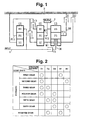
- Fig. 1 is a typical skeleton diagram of a speed change gear for an automatic transmission, according to an embodiment of the present invention.
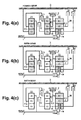
- Fig. 2 shows an engagement logic of a transmission friction element of the speed change gear, relative to a selected gear shift.
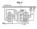
- Fig. 3 shows torque flow paths at each gear shift of the speed change gear according to the embodiment, in which:
- Fig. 4 shows torque flow paths at each gear shift of the speed change gear according to the embodiment, in which:
- Fig. 5 shows torque flow paths at a reverse gear shift of the speed change gear according to the embodiment, with a typical skeleton diagram similar to that in Fig. 1.
- Fig. 6 is a view of a developed cross section showing an actual constitution of the speed change gear in Fig. 1 to Fig. 5, according to the embodiment, in which:
- Fig. 7 shows an enlarged cross section of an essential part of the actual constitution of the speed change gear in Fig. 6, according to the embodiment of the present invention.
- Fig. 8 shows an automatic transmission achieving six forward gears and one reverse gear, according to a related art, in which improving on-vehicle mountability attributable to prevention of increase in axial length reduces gear noise.
- Fig. 1 shows a typical skeleton diagram of a speed change gear for an automatic transmission, according to an embodiment of the present invention.
- the speed change gear for the automatic transmission is so constituted that the first planetary gear set G1 (speed reduction, single pinion), the second planetary gear set G2 (single pinion), and the third planetary gear set G3 (double sun gear) are sequentially and substantially coaxially arranged from a left end (an end close to the input portion INPUT [input shaft 1]), as is seen in Fig. 1.
- the first planetary gear set G1 constitutes a speed reduction planetary gear set G1
- the second planetary gear set G2 and the third planetary gear set G3 constitute a speed change planetary gear set (a latter speed change mechanism).
- the first planetary gear set G1 has a first sun gear S1 a first ring gear R1, a first pinion P1 meshing with the first sun gear S1 and the first ring gear R1, and a first planetary carrier PC1 for carrying the first pinion P1 in such a manner that the first pinion P1 can rotate, thus constituting the single pinion planetary gear set (speed reduction planetary gear set G1).
- the second planetary gear set G2 has a second sun gear S2, a second ring gear R2, a second pinion P2 meshing with the second sun gear S2 and the second ring gear R2, and a second planetary carrier PC2 for carrying the second pinion P2 in such a manner that the second pinion P2 can rotate, thus constituting the single pinion planetary gear set.
- the third planetary gear set G3 has a third sun gear S3, a fourth sun gear S4, a third pinion P3 meshing with the third sun gear S3 and the fourth sun gear S4 in common, a third planetary carrier PC3 for carrying the third pinion P3 in such a manner that the third pinion P3 can rotate, and a third ring gear R3 (one in number) meshing with the third pinion P3, thus constituting the double sun gear planetary gear set.
- the third sun gear S3 is disposed on a nearer side to the input portion INPUT, while the fourth sun gear S4 is disposed on a farther side from the input portion INPUT.
- the numbers of teeth thereof need not to be equal (in other words, the different numbers of teeth are allowed).
- the third planetary carrier PC3 is provided with a center member CM united with the third planetary carrier PC3 and extending radially inward from between the third sun gear S3 and the fourth sun gear S4, and is provided with an outer member OM extending radially outward from the third planetary carrier PC3.
- the outer member OM is disposed actually in a special manner (to be described in detail afterward).
- the center member CM is so disposed to as to pass through a space which is defined on a circle formed with pitches arranged on the third pinion P3 and which is defined between the adjacent third pinions P3.
- the center member CM is so disposed as to extend radially inward from between the third sun gear S3 and the fourth sun gear S4.
- the input portion INPUT is constituted of the input shaft 1. Connecting the input shaft 1 to the first ring gear R1 and connecting the input shaft 1 to an engine (not shown) as power source via a torque converter (not shown) allow engine speed to be inputted from the input shaft 1 to the first ring gear R1.
- the output portion OUTPUT is constituted of an output gear 2.
- the output gear 2 substantially coaxially connects to the second connector member M2 (constituting a coupling body for coupling the second planetary carrier PC2 and the third ring gear R3), thus sending transmitted (changed speed) output rotation from the output gear 2 to a drive wheel of a vehicle via a final gear set (not shown) and a differential gear device (not shown).
- the first connector member M1 is a connector member for connecting the second sun gear S2 and the third sun gear S3 unitedly, thus constituting a coupling body for coupling the second sun gear S2 and the third sun gear S3.
- the first sun gear S1 of the speed reduction planetary gear set G1 is held continuously stationary.
- the first planetary carrier PC1 is adapted to be connected to the second ring gear R2 by the first clutch C1, and is adapted to be connected to the second sun gear S2 by the second clutch C2.
- the center member CM of the third planetary carrier PC3 is adapted to be connected to the input shaft 1 by the third clutch C3, thus allowing the third clutch C3 to act as a direct clutch outputting the input rotation to a compound planetary gear set (including the second planetary gear set G2 and the third planetary gear set G3) at a constant speed (namely, no speed change).
- the outer member OM of the third planetary carrier PC3 of the double sun gear planetary gear set G3 is adapted to be connected to the transmission case 3 by the first brake B1, and is adapted to hold stationary the third planetary carrier PC3.
- the fourth sun gear S4 is adapted to be connected to the transmission case 3 by the second brake B2, and thereby is adapted to be held stationary.
- the control valve body (not shown) for the transmission control is of a hydraulic pressure control type, an electronically control type, a combination of the former two, or the like.
- Fig. 2 shows an engagement logic of a transmission friction element of the speed change gear, relative to a selected gear shift.
- Fig. 3 to Fig. 5 show torque flow paths at each gear shift of the speed change gear, according to the embodiment.
- engaging the first clutch C1 and the first brake B1 may achieve the forward first gear.
- engaging the first clutch C1 may input a reduced rotation from the first planetary gear set G1 to the second ring gear R2.
- Fig. 3(a) shows the torque flow paths at the first gear, with the first clutch C1, the first brake B1 and each of the members indicated by the bold line and with the first planetary gear set G1, the second planetary gear set G2 and the third planetary gear set G3 (excluding the fourth sun gear S4) hatched.
- the bold line and the hatching teach that the torque is operated.
- all the planetary gear sets including the first planetary gear set G1 and the latter speed change mechanism may contribute to the torque flow.
- disengaging the first brake B1 (which is engaged at the first gear) while engaging the second brake B2, namely, engaging the first clutch C1 and the second brake B2 may achieve the forward second gear.
- engaging the first clutch C1 may input the reduced rotation from the first planetary gear set G1 to the second ring gear R2.
- engaging the second brake B2 may hold stationary the fourth sun gear S4 to the transmission case 3, thus holding stationary the third sun gear S3 which is connected to the fourth sun gear S4 by the third pinion P3. Then, the second sun gear S2 connected to the third sun gear S3 via the first connector member M1 may be held stationary to the transmission case 3.
- the forward reduced rotation is inputted from the second ring gear R2 while the second sun gear S2 is held stationary, thus further reducing the reduced rotation from the second ring gear R2.
- the thus further reduced rotation (although faster than the first speed) is to be outputted from the second planetary carrier PC2 to the output gear 2 via the second connector member M2.
- Fig. 3(b) shows the torque flow paths at the second gear, with the first clutch C1, the second brake B2 and each of the members indicated by the bold line and with the first planetary gear set G1 and the second planetary gear set G2 hatched.
- the bold line and the hatching teach that the torque is operated.
- the third pinion P3 free of constraint may revolve around the stationary sun gear S3 and the stationary sun gear S4 in accordance with the output rotation of the third ring gear R3.
- the third planetary gear set G3 may make substantially no contribution to the torque flow.
- disengaging the second brake B2 (which is engaged at the second gear) while engaging the second clutch C2, namely, engaging the first clutch C1 and the second clutch C2 may achieve the forward third gear.
- engaging the first clutch C1 may input the reduced rotation from the first planetary gear set G1 to the second ring gear R2. Substantially simultaneously with this, engaging the second clutch C2 may input the reduced rotation from the first planetary gear set G1 to the second sun gear S2 of the second planetary gear set G2.
- substantially the same reduced rotation is inputted to the second ring gear R2 and the second sun gear S2, thus outputting the reduced rotation (substantially the same as the reduced rotation from the first planetary gear set G1) to the output gear 2 via the second planetary carrier PC2 (rotating integrally with the second ring gear R2 and the second sun gear S2) and the second connector member M2.
- Fig. 3(c) shows the torque flow paths at the third gear, with the first clutch C1, the second clutch C2 and each of the members indicated by the bold line and with the first planetary gear set G1 and the second planetary gear set G2 hatched.
- the bold line and the hatching teach that the torque is operated.
- the third planetary gear set G3 may make substantially no contribution to the torque flow.
- disengaging the second clutch C2 (which is engaged at the third gear) while engaging the third clutch C3, namely, engaging the first clutch C1 and the third clutch C3 may achieve the forward fourth gear.
- engaging the first clutch C1 may input the reduced rotation from the first planetary gear set G1 to the second ring gear R2.
- engaging the third clutch C3 may input the input rotation from the input shaft 1 to the third planetary carrier PC3 via the center member CM.
- the rotation of the third sun gear S3 is more increased than the output rotation of the third ring gear R3.
- the thus increased rotation of the third sun gear S3 may be transmitted to the second sun gear S2 via the first connector member M1.
- the reduced rotation is inputted from the second ring gear R2 while the increased rotation is inputted from the second sun gear S2, thus increasing the reduced rotation from the second ring gear R2 (although lower than the input rotation).
- the thus increased rotation is to be outputted from the second planetary carrier PC2 to the output gear 2 via the second connector member M2.
- Fig. 4(a) shows the torque flow paths at the fourth gear, with the first clutch C1, the third clutch C3 and each of the members indicated by the bold line and with the first planetary gear set G1, the second planetary gear set G2 and the third planetary gear set G3 (excluding the fourth sun gear S4) hatched.
- the bold line and the hatching teach that the torque is operated.
- disengaging the first clutch C1 (which is engaged at the fourth gear) while engaging the second clutch C2, namely, engaging the second clutch C2 and the third clutch C3 may achieve the forward fifth gear.
- engaging the second clutch C2 may input the reduced rotation from the first planetary gear set G1 to the third sun gear S3 via the second sun gear S2 and the first connector member M1. Substantially simultaneously with this, engaging the third clutch C3 may input the input rotation from the input shaft 1 to the third planetary carrier PC3 via the center member CM.
- the input rotation is inputted to the third planetary carrier PC3 while the reduced rotation from the first planetary gear set G1 is inputted to the third sun gear S3, thus increasing the input rotation.
- the thus increased rotation (higher than the input rotation) is to be outputted from the third ring gear R3 to the output gear 2 via the second connector member M2.
- Fig. 4(b) shows the torque flow paths at the fifth gear, with the second clutch C2, the third clutch C3 and each of the members indicated by the bold line and with the first planetary gear set G1 and the third planetary gear set G3 (excluding the fourth sun gear S4) hatched.
- the bold line and the hatching teach that the torque is operated.
- disengaging the second clutch C2 (which is engaged at the fifth gear) while engaging the second brake B2, namely, engaging the third clutch C3 and the second brake B2 may achieve the forward sixth gear.
- engaging the third clutch C3 may input the input rotation from the input shaft 1 to the third planetary carrier PC3 via the center member CM of the third planetary gear set G3. Moreover, engaging the second brake B2 may hold stationary the fourth sun gear S4 of the third planetary gear set G3 to the transmission case 3.
- the input rotation is inputted to the third planetary carrier PC3 while the fourth sun gear S4 is held stationary to the transmission case 3, thus increasing the input rotation.
- the thus increased rotation is to be outputted from the third ring gear R3 to the output gear 2 via the second connector member M2.
- Fig. 4(c) shows the torque flow paths at the sixth gear, with the third clutch C3, the second brake B2 and each of the members indicated by the bold line and with the third planetary gear set G3 (excluding the third sun gear S3) hatched.
- the bold line and the hatching teach that the torque is operated.
- engaging the second clutch C2 and the first brake B1 may achieve the reverse gear.
- engaging the second clutch C2 may input the reduced rotation from the first planetary gear set G1 to third sun gear S3 via the second sun gear S2 and the first connector member M1.
- engaging the first brake B1 may hold stationary the planetary carrier PC3 to the transmission case 3.
- the forward reduced rotation is inputted to the third sun gear S3 while the third planetary carrier PC3 may be held stationary to the transmission case 3, thus outputting the reverse reduced rotation from the third ring gear R3 to the output gear 2 via the second connector member M2.
- Fig. 5 shows the torque flow paths at the reverse gear, with the second clutch C2, the first brake B1 and each of the members indicated by the bold line and with the first planetary gear set G1 and the third planetary gear set G3 (excluding the fourth sun gear S4) hatched.
- the bold line and the hatching teach that the torque is operated.
- Fig. 6 is a view of a developed cross section showing an actual constitution of the speed change gear in Fig. 1 to Fig. 5, while Fig. 7 is an enlarged cross section of an essential part of the actual constitution of the speed change gear in Fig. 6, according to the embodiment of the present invention.
- the input shaft 1 and a middle shaft 4 are disposed sidewise in Fig. 6 and Fig. 7 substantially coaxially in the transmission case 3, in such a manner as to mate and rotate relative to each other.
- the input shaft 1 and the middle shaft 4 are individually born in the transmission case 3 in such a manner as to rotate relative to the transmission case 3.
- the transmission case 3 has a front end opening (right in Fig. 6 and Fig. 7) closer to the input shaft 1, which opening is blocked with a pump case having a pump housing 5 and a pump cover 6.
- the input shaft 1 is inserted to the pump case to be born by the pump case.
- An engine (not shown) is drivingly connected to a protrusion end of the input shaft 1 via a torque converter (not shown).
- the middle shaft 4 has a rear end (farther side from the input shaft 1 in Fig. 6) which is rotatably born with an end cover 7 at a rear end (left in Fig. 6) of the transmission case 3.
- the output gear 2 is rotatably born by the middle wall 8.
- the input shaft 1 and the middle shaft 4 define a mating portion which is rotatably born by a wall defining a center opening of the middle wall 8 via a hollow shaft 9.
- the first planetary gear set G1 is disposed in the front space.
- the third clutch C3 is also disposed in the front space in such a manner as to wrap the first planetary gear set G1.
- the first sun gear S1 is serratedly held (or mated) stationary to a center boss 6a (protruding rearward [leftward in Fig. 6 and Fig. 7]) of the pump cover 6.
- the first sun gear S1 is thereby continuously incapable of rotating such that the first sun gear S1 can act as a reactive force receiver.
- the first ring gear R1 which acts as a rotation input member connects to an outer periphery of a flange 10 extending radially outward from the input shaft 1.
- the first ring gear R1 of the first planetary gear set G1 (speed reduction planetary gear set G1) and the third clutch C3 (direct clutch) disposed radially outward relative to the first ring gear R1 have the following constitution:
- the clutch hub and the first ring gear R1 are substantially the same in material.
- the first ring gear R1 is commonly used for the clutch hub of the third clutch C3.
- an outer periphery of the first ring gear R1 is provided with the clutch hub of the third clutch C3.
- the third clutch C3 has a clutch piston 13 (operation piston) which is disposed on a farther side (left in Fig. 7) of the first planetary gear set G1 from the oil pump case (including the pump housing 5 and the pump cover 6).
- the clutch piston 13 mates with an end wall 1 1a (facing the first planetary gear set G1) of the clutch drum 11, and with a front end of the middle shaft 4.
- the clutch piston 13 may make a stroke rightward in Fig. 6 and Fig. 7, thus engaging the third clutch C3.
- a connector member 51 extending radially outward from the front end of the hollow shaft 9, and then is shaped substantially into a drum in such a manner as to wrap the third clutch C3. Moreover, the connector member 51 has a front end (right in Fig. 6 and Fig. 7) connecting to the first planetary carrier PC 1.
- the first planetary carrier PC1 constitutes a rotation output member of the first planetary gear set G1.
- the second planetary gear set G2, the third planetary gear set G3, the first clutch C1, the second clutch C2, the first brake B1, and the second brake B2 are disposed in the rear space in Fig. 6 in the following manner:
- the second planetary gear set G2 and the third planetary gear set G3 are disposed on the middle shaft 4. In this case, however, the second planetary gear set G2 is disposed nearer to the input shaft 1 than the third planetary gear set G3.
- the first connector member M1 integrates the second sun gear S2 of the second planetary gear set G2 with the third sun gear S3 of the third planetary gear set G3.
- the thus integrated sun gear S2 and the third sun gear S3 are rotatably born on the middle shaft 4.
- a clutch drum 15 extending radially outward and then extending axially rearward (leftward in Fig. 6) to an outer periphery of the second ring gear R2, moreover, there is provided a clutch pack 16 having clutch plates which are splined respectively with an inner periphery of the clutch drum 15 and an outer periphery of the second ring gear R2 in such a manner as to be disposed alternatingly, thus constituting the first clutch C1
- the second clutch C2 is disposed nearer to the input shaft 1 than the first clutch C1 which is disposed on the outer periphery of the second planetary gear G2.
- a clutch hub 17 fixed to the outer end of the second sun gear S2 (on the input shaft 1's side of the second sun gear S2) and extending radially outward
- a clutch pack 18 having clutch plates which are splined respectively with an outer periphery of the clutch hub 17 and an inner periphery of the clutch drum 15 in such a manner as to be disposed alternatingly, thus constituting the second clutch C2.
- the clutch piston 19 of the first clutch C1 and the clutch piston 20 of the second clutch C2 are in combination disposed on the second clutch C2's side away from the first clutch C1.
- the clutch piston 20 may mate with the end wall (right in Fig. 6, and facing the second planetary gear set G2) of the clutch drum 15.
- the clutch piston 19 and the clutch piston 20 may make a stroke, thus engaging the first clutch C1 and the second clutch 20 individually.
- the third planetary gear set G3 is the double sun gear planetary gear set.
- the third ring gear R3 is smaller in tooth width than the third pinion P3.
- the third ring gear R3 may mesh with the third pinion P3 at an end portion near to the second planetary gear set G2, thus shortening the second connector member M2 for connecting the third ring gear R3 to the second planetary carrier PC2 of the second planetary gear set G2.
- a tubular connector member 22 disposed in such a manner as to wrap the clutch drum 15 of the first clutch C1 and the second clutch C2.
- the tubular connector member 22 has a first end (left in Fig. 6) connecting to the outer periphery of the third ring gear R3 and a second end (right in Fig. 6) connecting to the output gear 2.
- the third planetary carrier PC3 of the third planetary gear set G3 is fitted with the center member CM which extends radially inward via between the third sun gear S3 and the fourth sun gear S4. Moreover, substantially in an axial center of the third pinion P3, the third planetary carrier PC3 of the third planetary gear set G3 is fitted with the outer member OM extending radially outward substantially along an end face (left in Fig. 6) of the third ring gear R3.
- the center member CM is drivably connected to the middle shaft 4, thus connecting the third planetary carrier PC3 to the clutch drum 11 of the third clutch C3 via the center member CM and the middle shaft 4.
- the outer member OM has an outer periphery connecting to a brake hub 23. Being disposed around an outer periphery of the tubular connector member 22, the brake hub 23 extends frontward (rightward in Fig. 6) toward the middle wall 8.
- a brake pack 24 having brake plates which are splined respectively with an outer periphery at a front end (right in Fig. 6) of the brake hub 23 and an inner periphery of the transmission case 3 in such a manner as to be disposed alternatingly, thus constituting the first brake B1.
- the first brake B1 is adapted to be engaged by a brake piston 25 which mates in the transmission case 3 in a rearward position (left in Fig. 6) of the brake pack 24.
- the brake hub 26 disposed in such a manner as to cover the rear end (left in Fig. 6) of the brake hub 23.
- the brake hub 26 has a rear end wall 26a extending circumferentially inward substantially along a back portion of the third planetary gear set G3, moreover, an inner periphery of the rear end wall 26a of the brake hub 26 connects to the fourth sun gear S4 of the third planetary gear set G3.
- a brake pack 27 having brake plates which are splined respectively with an outer periphery of the brake hub 26 and the inner periphery of the transmission case 3, thus constituting the second brake B2.
- the second brake B2 is adapted to be engaged by a brake piston 28 which mates in the transmission case 3 in a rearward position (left in Fig. 6) of the brake pack 27.
- each of the first brake B1 and the second brake B2 is disposed outside the first clutch C1 and the second clutch C2. Moreover, the first brake B1 is disposed nearer to the input shaft 1 (or the first planetary gear set G1) than the second brake B2. The first brake B1 and the second brake B2 are, however, disposed nearer to the second planetary gear set G2 than the third planetary gear set G3.
- the compound planetary gear set (including the second planetary gear set G2 and the third planetary gear set G3) and the two clutches (including the first clutch C1 and the second clutch C2) are disposed on a side opposite to the input portion INPUT (input shaft 1) with respect to the speed reduction planetary gear set G1 (first planetary gear set G1).
- a one way clutch OWC is disposed between the front end (of the brake hub 23 constituting the first brake B1) and the transmission case 3. In a disengagement state of the first brake B1, the one way clutch OWC may prevent one way rotation of the third planetary carrier PC3, thus achieving the first gear.
- the OWC may allow a reverse rotation of the third planetary carrier PC3, thus rendering the engine brake unobtainable. Therefore, in case the engine brake is requested, the first brake B1 is engaged so as to prevent the reverse rotation of the third planetary carrier PC3.
- a counter shaft 29 extending substantially in parallel to the input shaft 1 and the middle shaft 4 is rotatably born in the transmission case 3.
- a counter gear 30 and a final drive pinion 31 are integrated with the counter shaft 29.
- the counter gear 30 may mesh with the output gear 2 while the final drive pinion 31 may mesh with the differential gear device (not shown in Fig. 6) between vehicle's drive wheels.
- the speed change gear for the automatic transmission that can make a selection from the six forward gears and one reverse gear has the following constitution:
- the outer periphery of the first ring gear R1 is integrated with the clutch hub of the third clutch C3, in the radial direction of the gear train, thus eliminating the need for securing an area for the following two:
- the above elimination of the area can prevent the transmission from becoming great in the radial direction and thereby secure a great outer diameter of the differential ring gear (not shown) relative to the distance between the main shaft and the differential shaft of the gear train.
- the third clutch C3 is smaller than a clutch(es) disposed on other portion(s).
- the above prevention of the automatic transmission from becoming enlarged in the axial direction and in the radial direction as well can reduce the gear noise and further can secure the great outer diameter of differential ring gear relative to the distance between the main shaft and the differential shaft of the gear train, resulting in improvement of the on-vehicle mountability.
- the speed change gear for the automatic transmission has the following constitution:
- the first planetary gear set G1 can have reduced diameter in the radial direction of the automatic transmission, thus securing the great diameter of differential ring gear relative to the distance between the main shaft and the differential shaft of the gear train.
- the speed change gear for the automatic transmission has the following constitution:
- the automatic transmission can be prevented from becoming large in the axial direction.
- the speed change gear for the automatic transmission has the following constitution:
- the input on the speed reduction side can be disposed in the vicinity of the input of the third clutch C3 (direct clutch), thus achieving a layout advantageous for the above effects.
- the clutch hub of the third clutch C3 and the first ring gear R1 of the first planetary gear set G1 are substantially the same in material, thus facilitating formation of the clutch hub of the third clutch C3 on the outer periphery of the first ring gear R1.
- the first planetary gear set G1 for the speed reduction is preferably has the constitution of the single pinion planetary gear set including the first ring gear R1 as the rotation input member and the first planetary carrier PC1 as the rotation output member.
- a double pinion planetary gear set is applicable for the first planetary gear set G1 which double pinion type may include the first planetary carrier PC1 as the rotation input member and the first ring gear R1 as the rotation output member.
Landscapes
- Engineering & Computer Science (AREA)
- General Engineering & Computer Science (AREA)
- Mechanical Engineering (AREA)
- Structure Of Transmissions (AREA)
Applications Claiming Priority (2)
| Application Number | Priority Date | Filing Date | Title |
|---|---|---|---|
| JP2002207330 | 2002-07-16 | ||
| JP2002207330A JP2004052807A (ja) | 2002-07-16 | 2002-07-16 | 自動変速機用歯車変速装置 |
Publications (1)
| Publication Number | Publication Date |
|---|---|
| EP1382883A2 true EP1382883A2 (de) | 2004-01-21 |
Family
ID=29774617
Family Applications (1)
| Application Number | Title | Priority Date | Filing Date |
|---|---|---|---|
| EP03016066A Withdrawn EP1382883A2 (de) | 2002-07-16 | 2003-07-15 | Gangverstellung für automatisches Getriebe |
Country Status (3)
| Country | Link |
|---|---|
| US (1) | US6918852B2 (de) |
| EP (1) | EP1382883A2 (de) |
| JP (1) | JP2004052807A (de) |
Cited By (1)
| Publication number | Priority date | Publication date | Assignee | Title |
|---|---|---|---|---|
| CN100458219C (zh) * | 2005-12-28 | 2009-02-04 | 丰田自动车株式会社 | 车辆用自动变速器 |
Families Citing this family (15)
| Publication number | Priority date | Publication date | Assignee | Title |
|---|---|---|---|---|
| DE60239331D1 (de) * | 2001-05-30 | 2011-04-14 | Jatco Ltd | Gangschalter für ein automatisches getriebe |
| JP3751916B2 (ja) * | 2002-07-16 | 2006-03-08 | ジヤトコ株式会社 | 自動変速機用歯車変速装置 |
| JP3830433B2 (ja) * | 2002-07-16 | 2006-10-04 | ジヤトコ株式会社 | 自動変速機用歯車変速装置 |
| JP3837125B2 (ja) * | 2003-06-04 | 2006-10-25 | ジヤトコ株式会社 | 車両用多段自動変速機 |
| KR100579302B1 (ko) * | 2004-06-21 | 2006-05-11 | 현대자동차주식회사 | 차량용 다단 자동 변속기 |
| JP2008291947A (ja) * | 2007-05-25 | 2008-12-04 | Mazda Motor Corp | 自動変速機 |
| US7828689B2 (en) * | 2007-08-24 | 2010-11-09 | Gm Global Technology Operations, Inc. | 8-speed transmission |
| CN101566217A (zh) * | 2009-06-03 | 2009-10-28 | 奇瑞汽车股份有限公司 | 六档自动变速器及其传动系统 |
| CN101566216A (zh) * | 2009-06-03 | 2009-10-28 | 奇瑞汽车股份有限公司 | 车用六档自动变速器及其传动系统 |
| DE102010010663A1 (de) * | 2010-03-01 | 2011-09-01 | A + M Fertigungstechnik Gmbh | Getriebe |
| US8591377B1 (en) * | 2012-05-29 | 2013-11-26 | Ford Global Technologies, Llc | Multi-speed automatic transmission |
| CN107606079B (zh) * | 2017-09-19 | 2023-09-08 | 陕西法士特齿轮有限责任公司 | 一种自动变速器 |
| CN108194587B (zh) * | 2017-12-29 | 2021-10-26 | 广州汽车集团股份有限公司 | 三行星排自动变速器及车辆 |
| CN110043633B (zh) * | 2019-04-17 | 2022-07-12 | 西南大学 | 行星系输入的双超越离合主轴输出的自动变速主轴总成 |
| CN111336224B (zh) * | 2020-03-30 | 2021-09-14 | 浙江东方机电有限公司 | 一种用于拖动系统的一体式电机 |
Citations (1)
| Publication number | Priority date | Publication date | Assignee | Title |
|---|---|---|---|---|
| JP2000055152A (ja) | 1998-07-31 | 2000-02-22 | Aisin Aw Co Ltd | 車両用自動変速機 |
Family Cites Families (7)
| Publication number | Priority date | Publication date | Assignee | Title |
|---|---|---|---|---|
| JPH02154844A (ja) * | 1988-12-06 | 1990-06-14 | Toyota Motor Corp | 自動変速機用歯車変速装置 |
| AT396245B (de) * | 1991-07-12 | 1993-07-26 | Vianova Kunstharz Ag | Verfahren zur herstellung von wasserverduennbaren lackbindemitteln und deren verwendung |
| DE19910299C1 (de) * | 1999-03-10 | 2001-04-19 | Daimler Chrysler Ag | Planetenräder-Wechselgetriebe mit drei Teilgetrieben |
| KR100341747B1 (ko) * | 1999-07-08 | 2002-06-22 | 이계안 | 자동변속기용 기어 트레인 |
| JP4665274B2 (ja) * | 1999-11-01 | 2011-04-06 | アイシン・エィ・ダブリュ株式会社 | 自動変速機の変速制御装置 |
| US6422968B1 (en) * | 2001-01-22 | 2002-07-23 | General Motors Corporation | Compact six speed power transmission |
| DE60239331D1 (de) * | 2001-05-30 | 2011-04-14 | Jatco Ltd | Gangschalter für ein automatisches getriebe |
-
2002
- 2002-07-16 JP JP2002207330A patent/JP2004052807A/ja active Pending
-
2003
- 2003-07-14 US US10/617,788 patent/US6918852B2/en not_active Expired - Fee Related
- 2003-07-15 EP EP03016066A patent/EP1382883A2/de not_active Withdrawn
Patent Citations (1)
| Publication number | Priority date | Publication date | Assignee | Title |
|---|---|---|---|---|
| JP2000055152A (ja) | 1998-07-31 | 2000-02-22 | Aisin Aw Co Ltd | 車両用自動変速機 |
Cited By (1)
| Publication number | Priority date | Publication date | Assignee | Title |
|---|---|---|---|---|
| CN100458219C (zh) * | 2005-12-28 | 2009-02-04 | 丰田自动车株式会社 | 车辆用自动变速器 |
Also Published As
| Publication number | Publication date |
|---|---|
| US20040014549A1 (en) | 2004-01-22 |
| US6918852B2 (en) | 2005-07-19 |
| JP2004052807A (ja) | 2004-02-19 |
Similar Documents
| Publication | Publication Date | Title |
|---|---|---|
| US6918852B2 (en) | Speed change gear for automatic transmission | |
| US8771130B2 (en) | Automatic transmission | |
| US9989127B2 (en) | Automatic transmission | |
| US6935985B2 (en) | Gear change-speed unit for automatic transmission | |
| JP2000220705A (ja) | 車両用自動変速機 | |
| EP1923604B1 (de) | Automatikgetriebe | |
| JP3721813B2 (ja) | 車両用自動変速機 | |
| US6790155B2 (en) | Speed change gear for automatic transmission | |
| US6988426B2 (en) | Dual range countershaft transmission | |
| CN101375084B (zh) | 自动变速器 | |
| EP1389696B1 (de) | Gangverstellung für automatische Getriebe | |
| US20250052308A1 (en) | Transmission and Drive Device for a Motor Vehicle | |
| JP4230728B2 (ja) | 自動変速機用摩擦要素の作動油路構造 | |
| US7052431B2 (en) | Automatic transmission | |
| JP3834285B2 (ja) | 自動変速機 | |
| JP2004052813A (ja) | 自動変速機用歯車変速装置 | |
| JPWO2004061332A1 (ja) | 自動変速機 | |
| JP3941270B2 (ja) | 車両用自動変速機 | |
| JP2004052804A (ja) | 自動変速機 | |
| JP4424426B2 (ja) | 車両用自動変速機 | |
| JP4345863B2 (ja) | 車両用自動変速機 | |
| JP3734459B2 (ja) | 自動変速機 | |
| JPH09272352A (ja) | 車両用トランスミッション | |
| JPH0979326A (ja) | 自動変速機 |
Legal Events
| Date | Code | Title | Description |
|---|---|---|---|
| PUAI | Public reference made under article 153(3) epc to a published international application that has entered the european phase |
Free format text: ORIGINAL CODE: 0009012 |
|
| 17P | Request for examination filed |
Effective date: 20030715 |
|
| AK | Designated contracting states |
Kind code of ref document: A2 Designated state(s): AT BE BG CH CY CZ DE DK EE ES FI FR GB GR HU IE IT LI LU MC NL PT RO SE SI SK TR |
|
| AX | Request for extension of the european patent |
Extension state: AL LT LV MK |
|
| STAA | Information on the status of an ep patent application or granted ep patent |
Free format text: STATUS: THE APPLICATION HAS BEEN WITHDRAWN |
|
| 18W | Application withdrawn |
Effective date: 20051012 |