EP1382838A2 - Brennstoffeinspritzventil - Google Patents
Brennstoffeinspritzventil Download PDFInfo
- Publication number
- EP1382838A2 EP1382838A2 EP03012488A EP03012488A EP1382838A2 EP 1382838 A2 EP1382838 A2 EP 1382838A2 EP 03012488 A EP03012488 A EP 03012488A EP 03012488 A EP03012488 A EP 03012488A EP 1382838 A2 EP1382838 A2 EP 1382838A2
- Authority
- EP
- European Patent Office
- Prior art keywords
- actuator
- piston
- fuel injection
- injection valve
- fuel
- Prior art date
- Legal status (The legal status is an assumption and is not a legal conclusion. Google has not performed a legal analysis and makes no representation as to the accuracy of the status listed.)
- Granted
Links
- 239000000446 fuel Substances 0.000 title claims description 75
- 238000013016 damping Methods 0.000 claims abstract description 27
- 238000002347 injection Methods 0.000 claims description 14
- 239000007924 injection Substances 0.000 claims description 14
- 238000002485 combustion reaction Methods 0.000 claims description 6
- 230000000694 effects Effects 0.000 claims description 3
- 238000007789 sealing Methods 0.000 claims description 3
- 230000005540 biological transmission Effects 0.000 claims description 2
- 239000007921 spray Substances 0.000 description 22
- 239000012530 fluid Substances 0.000 description 5
- 230000004913 activation Effects 0.000 description 3
- 239000012528 membrane Substances 0.000 description 3
- 238000000034 method Methods 0.000 description 3
- 230000001627 detrimental effect Effects 0.000 description 2
- 238000004519 manufacturing process Methods 0.000 description 2
- 230000002411 adverse Effects 0.000 description 1
- 238000009795 derivation Methods 0.000 description 1
- 238000011161 development Methods 0.000 description 1
- 230000018109 developmental process Effects 0.000 description 1
- 230000005284 excitation Effects 0.000 description 1
- 238000005304 joining Methods 0.000 description 1
- 238000004904 shortening Methods 0.000 description 1
- 239000000243 solution Substances 0.000 description 1
- 230000001629 suppression Effects 0.000 description 1
Images

Classifications
-
- F—MECHANICAL ENGINEERING; LIGHTING; HEATING; WEAPONS; BLASTING
- F02—COMBUSTION ENGINES; HOT-GAS OR COMBUSTION-PRODUCT ENGINE PLANTS
- F02M—SUPPLYING COMBUSTION ENGINES IN GENERAL WITH COMBUSTIBLE MIXTURES OR CONSTITUENTS THEREOF
- F02M61/00—Fuel-injectors not provided for in groups F02M39/00 - F02M57/00 or F02M67/00
- F02M61/04—Fuel-injectors not provided for in groups F02M39/00 - F02M57/00 or F02M67/00 having valves, e.g. having a plurality of valves in series
- F02M61/08—Fuel-injectors not provided for in groups F02M39/00 - F02M57/00 or F02M67/00 having valves, e.g. having a plurality of valves in series the valves opening in direction of fuel flow
-
- F—MECHANICAL ENGINEERING; LIGHTING; HEATING; WEAPONS; BLASTING
- F02—COMBUSTION ENGINES; HOT-GAS OR COMBUSTION-PRODUCT ENGINE PLANTS
- F02M—SUPPLYING COMBUSTION ENGINES IN GENERAL WITH COMBUSTIBLE MIXTURES OR CONSTITUENTS THEREOF
- F02M51/00—Fuel-injection apparatus characterised by being operated electrically
- F02M51/06—Injectors peculiar thereto with means directly operating the valve needle
- F02M51/0603—Injectors peculiar thereto with means directly operating the valve needle using piezoelectric or magnetostrictive operating means
-
- F—MECHANICAL ENGINEERING; LIGHTING; HEATING; WEAPONS; BLASTING
- F02—COMBUSTION ENGINES; HOT-GAS OR COMBUSTION-PRODUCT ENGINE PLANTS
- F02M—SUPPLYING COMBUSTION ENGINES IN GENERAL WITH COMBUSTIBLE MIXTURES OR CONSTITUENTS THEREOF
- F02M61/00—Fuel-injectors not provided for in groups F02M39/00 - F02M57/00 or F02M67/00
- F02M61/16—Details not provided for in, or of interest apart from, the apparatus of groups F02M61/02 - F02M61/14
- F02M61/167—Means for compensating clearance or thermal expansion
Definitions
- the invention is based on a fuel injector according to the genus of the main claim.
- DE 43 06 072 A1 describes a device for opening and closing one in one housing existing passage opening known, which also as Fuel injector can be used.
- This Device has a piezoelectric, magnetostrictive or electostrictive actuator and one with this actuator in Operational connection standing pressure piston on the Hydraulic fluid acts on a reciprocating piston.
- the reciprocating piston actuates the one in its extension Valve closing body.
- the gap and a pressure in the second chamber is like this dimensioned that slow, due to thermal influence changes in length of the actuator by exchanging Hydraulic fluid balanced through the guide gap can be.
- Modern internal combustion engines often require a relative short activation time of the fuel injector.
- the this causes steep flanks for control of a piezo actuator cause in the piezo actuator, especially on End of the edge around the target voltage level, relative high frequency unwanted vibrations that are stable Operation of the fuel injector in particular Oppose partial stroke operation.
- a disadvantage of that from the above publication known fuel injector is in particular that special measures or components to suppress unwanted vibrations of parts of the Fuel injector, in particular by the Behavior of the actuator are caused, completely absent and insufficiently suppressed by the existing components or be balanced. So a stable behavior of the Fuel injector through the use or Exploitation of frictional forces between the components of the fuel injector and by forces of Spring elements insufficiently achieved. There called forces are relatively constant over a wide range this that when suppressing unwanted Vibrations the valve dynamics suffer to the same extent. The Use of spring or sliding friction forces unsuitable for the suppression of high-frequency Vibrations.
- the activation times or the target voltage times must be sufficient to prevent unwanted vibrations dampen the spring and sliding friction forces between the components are increased.
- this is the Valve dynamics detrimental and requires the actuator Overcoming additional increased forces.
- the actuator and the parts that are operatively connected to it are thereby increased demands.
- the publication DE 43 06 072 A1 known invention is therefore a shortening of Control times and target voltage times only in short Limits possible, which are also detrimental to the service life of the fuel injector or go cost-intensive measures must be accompanied.
- the fuel injector according to the invention with the has characteristic features of the main claim in contrast, the advantage that mechanical vibrations in Fuel injector, especially unwanted mechanical vibrations of the actuator and through it unwanted vibrations in moving parts of the fuel injector according to the invention simple and inexpensive way effectively dampened without significantly affecting the valve dynamics or stress components significantly more.
- the activation times of the actuator increase significantly shortened and thus in particular a partial stroke operation of the fuel injector.
- the Edge times of the actuator excitation and the plateau times can can be shortened without the actuator in particular generated vibrations negatively on the operation of the Fuel injector impact or valve dynamics is significantly adversely affected.
- the Damping effect is based on hydraulic operating principles, it is largely wear-free. Through flowing movements of a pressure medium through a restriction in particular possible to achieve a damping force that is proportional to the speed of the actuator movements, behaves like a linear attenuator.
- the Assembly is also simplified.
- the throttle point is advantageously through a gap formed in conjunction with a first one Guide body either from a thickened or tapered Part of the stage of the actuator piston is formed. That is it possible on constructive as well as functional requirements to respond better. Another advantage is that Throttle point as a bore, especially as a laser bore manufacture, as these are particularly precise, fast and is inexpensive to manufacture. Will fuel as Pressure medium used, so in particular constructive Measures to separate fuel and pressure medium omitted. Furthermore, fuel channel and is advantageous Place throttle so that fuel immediately is exchanged between them. This reduces the constructive effort.
- Fuel injector be designed so that by at least one of the guide columns of actuator pistons and Piston pressure medium the work area relatively slowly tiling or escaping from it.
- the size ratio of the Surfaces of the two pistons facing the work area are realized, a stroke ratio.
- the invention can be advantageously further developed Fuel injector also in that the Force of a spring element is dimensioned at least as large, that actuator piston, connecting element and actuator in constant Are held. This will make the appropriate Components when operating the fuel injector prevented from losing contact with each other and collide with each other. It can be costly and expensive wear-prone joining connections are dispensed with.
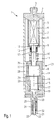
- a first embodiment of a shown in FIG Fuel injector 1 according to the invention is in the Form of a fuel injector 1 for Fuel injection systems from mixture-compressing, spark-ignition internal combustion engines.
- the Fuel injection valve 1 is particularly suitable for not directly injecting fuel into one Shown combustion chamber of an internal combustion engine.
- the fuel injector 1 has a housing cover 2 which on the distal end of a valve housing 5 sits hermetically sealed. Via a fuel connection 3 on the housing cover 2 is a fuel channel 6 with fuel acted upon.
- the fuel channel 6 is only running inside the housing cover 2 and then inside the Valve housing 5, the upper part of the Fuel injector 1, an actuator housing 7, a Seal 12, an extension ring 10 of an actuator piston 9, the part of the actuator piston 9 remote from the spray and a first one Spring element 11 is flushed with fuel in the fuel channel 6 become.
- the actuator housing 7 is remote from its spray End hermetically connected to the housing cover 2.
- An actuator 4 located in the actuator housing 7 is connected to its discharge side assigned to the housing cover 2 and is based on this.
- a connecting element 8 is with its plate-shaped end remote from the spray near the spray Assigned side of the actuator 4 and engages with his tapered diameter curve on the spray side by a Opening 18 of the actuator housing 7.
- a seal 12 which in this embodiment of the invention Fuel injector 1 is corrugated, represents by their hermetic fastening of both ends on the one hand on a spray side as an attachment ring 13 molded part of the connecting element 8 and the other at the spray end of the actuator housing 7, make sure that the fuel under pressure is not in that Actuator housing 7 can penetrate and the connecting element 8 the Movements of the actuator 4 or the movements of the actuator piston 9 can follow unhindered.
- the actuator piston 9 has a Level 31, which is tapered by its remote spray Diameter course is formed.
- the thicker spray-side course of the actuator piston 9 is in one first guide body 14 with a first guide gap 28 guided.
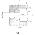
- the tapered, tapered diameter profile of the Actuator piston 9 forms one with the first guide body 14 Gap that forms the throttle point 30, the Guide body 14 at this point the tapered Diameter course of the actuator piston 9 follows, that is one has a reduced inner diameter.
- the result Damping chamber 27 is used to dampen unwanted vibrations of parts of the Fuel injection valve, in particular for damping Actuator vibrations in both directions of movement of the actuator 4 during operation of the fuel injector 1.
- the Damping properties are particularly by the Geometric dimensions of the throttling point 30 Gap and the damping chamber 27 determined.
- the in Spray direction perpendicular distance between the tapered diameter profile of the actuator piston 9 and the at this point the reduced inside diameter of the Guide body 14 is generally larger than that corresponding distance through the first guide gap 28 is formed.
- the actuator piston 9 is supported by the first spring element 11, which in this embodiment is a spiral spring is formed and on one on the spray remote tapered diameter profile of the actuator piston 9 attached first attachment ring 10 attacks against spray near the side of the connecting element 8 or against the Actuator 4 biased, the first spring element 11 is supported on the spray side against the first guide body 14.
- a second guide body 16 is hermetically sealed with the spray-side side of the first guide body 14 connected, wherein a reciprocating piston 15 with a second Guide gap 29 is guided in the second guide body 16.
- a work space 26 which through the first guide body 14 and the second guide body 16 is limited, wherein the two guide columns 28, 29 each with one end in open the working space 26.
- the second end of the first Guide gap 28 opens into the damping chamber 27, the second end of the second guide gap opens on injection-side end of the second guide body 16 in the Fuel channel 6.
- the fuel channel 6 runs in the lower part of the Fuel injector 1 first between housing 5 and the two guide bodies 14, 16. Then happens and flows around the fuel in the fuel channel 6 from the Guide body 16 protruding part of the reciprocating piston 15, a third formed in the course of the reciprocating piston 15 Neck ring 19, a between the third neck ring and the spray-side end of the second guide body 16 bordered second spring element 17, one with the reciprocating piston 15 operatively connected valve needle 20 with a fourth extension ring 25, one between the fourth extension ring 25 and a shoulder 32 bordered third spring element 24.
- the fuel injector works like follows:
- the valve closing body 22 and valve seat body 21 formed sealing seat is initially closed.
- the actuator 4 is discharged and the damping chamber 27 has a small one Volume. If the actuator 4 is now loaded, it expands relatively quickly and presses the connecting element 8 to the Actuator piston 9 in the spray direction.
- the Spring force of the first spring element 11 are overcome, on the other hand, the increasing volume of the Damping chamber 27 with fuel, which by the Throttle point 30 flows into the damping chamber 27.
- A creates the movement of the actuator piston 9 opposing, damping force is proportional to the Speed of the actuator piston 9, so behaves like with a linear attenuator. Through this process undesirable vibrations are dampened.
- the actuator piston 9 now presses over the working space 26 filled with fuel the piston 15 in the spray direction.
- the gap represented by the throttle point 30 can also be used for management tasks.
- FIG. 2 shows a large part of that in FIG. 1 illustrated first embodiment similar second Embodiment.
- the actuator piston 9 is cup-shaped and has step 31 in its diameter profile, whereby the diameter curve against the spray direction is enlarged.
- step 31 By level 31 and one in the area of Stage 31 lying enlarged inner diameter of the
- the damping chamber 27 is formed in the guide body 14.
- the Connecting element 8 reaches to the bottom of the cup-shaped executed actuator piston 9, wherein the actuator piston 9 or the bottom of the actuator piston 9 by the spring element 11 are biased against the connecting element 8.
- the Spring element 11 is in this embodiment as Bourdon tube executed and on the inside of the Housing cover 2 and at the far end of the Cup-shaped Akfcorkkolben 9 non-positively attached.
- the annular surface A of the actuator piston 9 on the damping chamber 27 is:
- C is a constant that is different from the geometric Dimension of the annular gap depends and ⁇ p represents the Pressure difference.
- the invention is not shown on the Embodiments limited and z. B. also for after internal fuel injectors can be used.
Landscapes
- Engineering & Computer Science (AREA)
- Chemical & Material Sciences (AREA)
- Combustion & Propulsion (AREA)
- Mechanical Engineering (AREA)
- General Engineering & Computer Science (AREA)
- Fuel-Injection Apparatus (AREA)
Abstract
Description
- Fig. 1
- einen schematischen Schnitt durch ein erstes Ausführungsbeispiel eines erfindungsgemäß ausgestalteten Brennstoffeinspritzventils,
- Fig. 2
- einen schematischen Schnitt durch ein zweites Ausführungsbeispiel eines erfindungsgemäß ausgestalteten Brennstoffeinspritzventils und
- Fig. 3
- einen schematisch dargestellten Teilschnitt des in Fig. 1 dargestellten Ausführungsbeispiels im Bereich der Stufe und der Dämpfungskammer.

Claims (10)
- Brennstoffeinspritzventil (1), insbesondere zum direkten Einspritzen von Brennstoff in einen Brennraum einer Brennkraftmaschine, mit
einem piezoelektrischen, elektrostriktiven oder magnetostrikiven Aktor (4),
einem mit dem Aktor (4) in Wirkverbindung stehenden Aktorkolben (9), der mit einem ersten Führungsspalt (28) geführt ist,
einem mit dem Aktorkolben (9) über ein Druckmedium in Wirkverbindung stehenden Hubkolben (15), der mit einem zweiten Führungsspalt (29) geführt ist,
einer mit dem Hubkolben (15) in Wirkverbindung stehenden Ventilnadel (20), die an ihrem abspritzseitigen Ende einen Ventilschließkörper (22) aufweist, der mit einem Ventilsitzkörper (21) einen Dichtsitz bildet,
wobei die Kraftübertragung zwischen Aktorkolben (9) und Hubkolben (15) durch einen mit Druckmedium gefüllten, von Aktorkolben (9) und Hubkolben (15) eingeschlossenen Arbeitsraum (26) erfolgt,
dadurch gekennzeichnet, daß der Aktorkolben (9) zumindest eine Stufe (31) aufweist, die an eine Dämpfungskammer (27) angrenzt, wobei die Dämpfungskammer (27) vom Arbeitsraum (26) räumlich getrennt ist und so gestaltet bzw. angeordnet ist, daß Druckmedium über eine Drosselstelle (30) zufließen bzw. abfließen kann. - Brennstoffeinspritzventil nach Anspruch 1,
dadurch gekennzeichnet, daß die Drosselstelle (30) durch einen Spalt gebildet ist, der von einem verjüngten Teil der Stufe (31) des Aktorkolbens (9) und einem Führungskörper (14) gebildet ist. - Brennstoffeinspritzventil nach Anspruch 1,
dadurch gekennzeichnet, daß die Drosselstelle (30) durch einen Spalt gebildet ist, der von einem verdickten Teil der Stufe (31) des Aktorkolbens (9) und einem Führungskörper (14) gebildet ist. - Brennstoffeinspritzventil nach Anspruch 2 oder 3,
dadurch gekennzeichnet, daß der Führungskörper (14) aus mehreren Teilen besteht. - Brennstoffeinspritzventil nach einem der Ansprüche 1 bis 4,
dadurch gekennzeichnet, daß die Drosselstelle (30) durch eine Öffnung, insbesondere eine Bohrung oder Laserbohrung, gebildet ist, welche eine strömungsdrosselnde Wirkung aufweist. - Brennstoffeinspritzventil nach einem der vorangegangenen Ansprüche,
dadurch gekennzeichnet, daß der Brennstoff als Druckmedium dient. - Brennstoffeinspritzventil nach Anspruch 6,
dadurch gekennzeichnet, daß über die Drosselstelle (30) unmittelbar Brennstoff mit einem Brennstoffkanal (6) ausgetauscht wird. - Brennstoffeinspritzventil nach einem der vorangegangenen Ansprüche,
dadurch gekennzeichnet, daß zum Ausgleich von temperaturbedingten Längenänderungen des Aktors (4) durch zumindest einen der Führungsspalte (28,29) Druckmedium aus dem Arbeitsraum (26) fließt oder in den Arbeitsraum (26) fließt. - Brennstoffeinspritzventil nach einem der vorangegangenen Ansprüche,
dadurch gekennzeichnet, daß die Kraft eines Federelements (11) mindestens so groß ist, daß der Aktorkolben (9), ein Verbindungselement (8) und der Aktor (4) in ständiger Anlage gehalten werden. - Brennstoffeinspritzventil nach einem der vorangegangenen Ansprüche,
dadurch gekennzeichnet, daß durch das Verhältnis der Flächen des Aktorkolbens (9) und des Hubkolbens (15) die dem Arbeitsraum (26) zugewandt sind, eine Hubübersetzung gegeben ist.
Applications Claiming Priority (2)
| Application Number | Priority Date | Filing Date | Title |
|---|---|---|---|
| DE10232193 | 2002-07-16 | ||
| DE2002132193 DE10232193A1 (de) | 2002-07-16 | 2002-07-16 | Brennstoffeinspritzventil |
Publications (3)
| Publication Number | Publication Date |
|---|---|
| EP1382838A2 true EP1382838A2 (de) | 2004-01-21 |
| EP1382838A3 EP1382838A3 (de) | 2004-04-21 |
| EP1382838B1 EP1382838B1 (de) | 2017-08-16 |
Family
ID=29761999
Family Applications (1)
| Application Number | Title | Priority Date | Filing Date |
|---|---|---|---|
| EP03012488.7A Expired - Lifetime EP1382838B1 (de) | 2002-07-16 | 2003-06-02 | Brennstoffeinspritzventil |
Country Status (3)
| Country | Link |
|---|---|
| EP (1) | EP1382838B1 (de) |
| JP (1) | JP2004052767A (de) |
| DE (1) | DE10232193A1 (de) |
Cited By (7)
| Publication number | Priority date | Publication date | Assignee | Title |
|---|---|---|---|---|
| WO2005068820A1 (de) * | 2004-01-16 | 2005-07-28 | Robert Bosch Gmbh | Kraftstoffinjektor mit direkter nadelsteuerung |
| WO2005068821A1 (de) * | 2004-01-16 | 2005-07-28 | Robert Bosch Gmbh | Kraftstoffinjektor mit direkt angesteuertem einspritzventilglied |
| WO2005111407A1 (de) * | 2004-05-14 | 2005-11-24 | Siemens Aktiengesellschaft | Düsenbaugruppe und einspritzventil |
| WO2006003048A1 (de) | 2004-07-01 | 2006-01-12 | Robert Bosch Gmbh | Common-rail-injektor |
| WO2006092344A1 (de) * | 2005-03-01 | 2006-09-08 | Robert Bosch Gmbh | Kraftstoffinjektor mit direktgesteuertem einspritzventilglied mit doppelsitz |
| FR2889257A1 (fr) * | 2005-08-01 | 2007-02-02 | Renault Sas | Dispositif d'injection de carburant et procede de commande d'un tel dispositif |
| WO2007124971A1 (de) * | 2006-04-26 | 2007-11-08 | Robert Bosch Gmbh | Injektor |
Families Citing this family (5)
| Publication number | Priority date | Publication date | Assignee | Title |
|---|---|---|---|---|
| US9897058B2 (en) | 2009-07-29 | 2018-02-20 | Delphi International Operations S.A.R.L. | Fuel injector |
| ATE552420T1 (de) | 2009-07-29 | 2012-04-15 | Delphi Tech Holding Sarl | Kraftstoffeinspritzdüse |
| CN102213165B (zh) * | 2010-04-08 | 2013-02-13 | 北京亚新科天纬油泵油嘴股份有限公司 | 高压共轨电控喷油器 |
| JP5462143B2 (ja) * | 2010-12-09 | 2014-04-02 | 株式会社日本自動車部品総合研究所 | 燃料噴射弁 |
| JP5839228B2 (ja) * | 2011-11-21 | 2016-01-06 | 株式会社デンソー | 燃料噴射弁 |
Citations (1)
| Publication number | Priority date | Publication date | Assignee | Title |
|---|---|---|---|---|
| DE4306072A1 (de) | 1993-02-26 | 1994-09-08 | Siemens Ag | Vorrichtung zum Öffnen und Verschließen einer in einem Gehäuse vorhandenen Durchtrittsöffnung |
Family Cites Families (9)
| Publication number | Priority date | Publication date | Assignee | Title |
|---|---|---|---|---|
| DE3332808A1 (de) * | 1983-09-12 | 1985-03-28 | Robert Bosch Gmbh, 7000 Stuttgart | Kraftstoff-einspritzduese fuer brennkraftmaschinen |
| JP3736578B2 (ja) * | 1996-01-19 | 2006-01-18 | 株式会社デンソー | 燃料噴射ノズル |
| DE19642441A1 (de) * | 1996-10-15 | 1998-04-16 | Bosch Gmbh Robert | Verfahren zum Betätigen eines Kraftstoffeinspritzventils für Brennkraftmaschinen |
| GB2339451A (en) * | 1998-07-10 | 2000-01-26 | Lucas Ind Plc | A fuel injector with control chamber and a damped needle valve |
| DE19946828C1 (de) * | 1999-09-30 | 2001-07-12 | Bosch Gmbh Robert | Ventil zum Steuern von Flüssigkeiten |
| GB9925803D0 (en) * | 1999-11-02 | 1999-12-29 | Lucas Industries Ltd | Damping device |
| DE19962177A1 (de) * | 1999-12-22 | 2001-07-12 | Siemens Ag | Hydraulische Vorrichtung zum Übertragen einer Aktorbewegung |
| DE10121891A1 (de) * | 2001-05-05 | 2002-11-07 | Bosch Gmbh Robert | Kraftstoffeinspritzventil für Brennkraftmaschinen |
| DE10155229B4 (de) * | 2001-11-09 | 2004-07-15 | Robert Bosch Gmbh | Ventil zum Steuern von Flüssigkeiten |
-
2002
- 2002-07-16 DE DE2002132193 patent/DE10232193A1/de not_active Withdrawn
-
2003
- 2003-06-02 EP EP03012488.7A patent/EP1382838B1/de not_active Expired - Lifetime
- 2003-07-14 JP JP2003196577A patent/JP2004052767A/ja active Pending
Patent Citations (1)
| Publication number | Priority date | Publication date | Assignee | Title |
|---|---|---|---|---|
| DE4306072A1 (de) | 1993-02-26 | 1994-09-08 | Siemens Ag | Vorrichtung zum Öffnen und Verschließen einer in einem Gehäuse vorhandenen Durchtrittsöffnung |
Cited By (12)
| Publication number | Priority date | Publication date | Assignee | Title |
|---|---|---|---|---|
| WO2005068820A1 (de) * | 2004-01-16 | 2005-07-28 | Robert Bosch Gmbh | Kraftstoffinjektor mit direkter nadelsteuerung |
| WO2005068821A1 (de) * | 2004-01-16 | 2005-07-28 | Robert Bosch Gmbh | Kraftstoffinjektor mit direkt angesteuertem einspritzventilglied |
| WO2005111407A1 (de) * | 2004-05-14 | 2005-11-24 | Siemens Aktiengesellschaft | Düsenbaugruppe und einspritzventil |
| US7934669B2 (en) | 2004-05-14 | 2011-05-03 | Continental Automotive Gmbh | Nozzle assembly and injection valve |
| WO2006003048A1 (de) | 2004-07-01 | 2006-01-12 | Robert Bosch Gmbh | Common-rail-injektor |
| US7418949B2 (en) | 2004-07-01 | 2008-09-02 | Robert Bosch Gmbh | Common rail injector |
| WO2006092344A1 (de) * | 2005-03-01 | 2006-09-08 | Robert Bosch Gmbh | Kraftstoffinjektor mit direktgesteuertem einspritzventilglied mit doppelsitz |
| FR2889257A1 (fr) * | 2005-08-01 | 2007-02-02 | Renault Sas | Dispositif d'injection de carburant et procede de commande d'un tel dispositif |
| WO2007015022A1 (fr) * | 2005-08-01 | 2007-02-08 | Renault S.A.S | Dispositif d'injection de carburant et procede de commande d'un tel dispositif |
| US7784708B2 (en) | 2005-08-01 | 2010-08-31 | Renault S.A.S. | Fuel injecting device and method for controlling said device |
| CN101233313B (zh) * | 2005-08-01 | 2011-02-16 | 雷诺股份公司 | 燃料喷射装置以及用于控制所述装置的方法 |
| WO2007124971A1 (de) * | 2006-04-26 | 2007-11-08 | Robert Bosch Gmbh | Injektor |
Also Published As
| Publication number | Publication date |
|---|---|
| DE10232193A1 (de) | 2004-02-05 |
| JP2004052767A (ja) | 2004-02-19 |
| EP1382838A3 (de) | 2004-04-21 |
| EP1382838B1 (de) | 2017-08-16 |
Similar Documents
| Publication | Publication Date | Title |
|---|---|---|
| DE19500706C2 (de) | Zumeßventil zur Dosierung von Flüssigkeiten oder Gasen | |
| EP1259729B1 (de) | Magnetventil zur steuerung eines einspritzventils einer brennkraftmaschine | |
| DE19712921A1 (de) | Brennstoffeinspritzventil mit piezoelektrischem oder magnetostriktivem Aktor | |
| DE19709794A1 (de) | Ventil zum Steuern von Flüssigkeiten | |
| EP1382838B1 (de) | Brennstoffeinspritzventil | |
| DE19946840A1 (de) | Ventil zum Steuern von Flüssigkeiten | |
| EP1831540A1 (de) | Kraftstoffinjektor mit direkt angesteuertem einspritzventilglied | |
| DE10217594A1 (de) | Brennstoffeinspritzventil | |
| DE10019764B4 (de) | Ventil zum Steuern von Flüssigkeiten | |
| EP1685323B1 (de) | Vorrichtung zum dämpfen von druckstössen | |
| EP1593841B1 (de) | Brennstoffeinspritzventil | |
| DE19925102B4 (de) | Brennstoffeinspritzventil | |
| DE102022204538A1 (de) | Gasinjektor mit kompakter Bauweise | |
| EP1319127A1 (de) | Ventilausbildung für steuerventile | |
| DE19939133A1 (de) | Brennstoffeinspritzventil | |
| DE10355645A1 (de) | Brennstoffeinspritzsystem | |
| DE10145622A1 (de) | Ventil zum Steuern von Flüssigkeiten | |
| DE19858476B4 (de) | Vorrichtung zum Übertragen einer Aktorauslenkung auf ein Stellglied und Einspritzventil mit einer solchen Vorrichtung | |
| EP1714026B1 (de) | Brennstoffeinspritzventil | |
| DE10353641B4 (de) | Brennstoffeinspritzventil | |
| EP1519035A1 (de) | Brennstoffeinspritzventil | |
| DE10344880A1 (de) | Brennstoffeinspritzventil | |
| DE102004002134A1 (de) | Brennstoffeinspritzventil | |
| WO2005031152A1 (de) | Einspritzventil mit einem hydraulischen ausgleichselement | |
| DE102007011788A1 (de) | Kraftstoffinjektor |
Legal Events
| Date | Code | Title | Description |
|---|---|---|---|
| PUAI | Public reference made under article 153(3) epc to a published international application that has entered the european phase |
Free format text: ORIGINAL CODE: 0009012 |
|
| AK | Designated contracting states |
Kind code of ref document: A2 Designated state(s): AT BE BG CH CY CZ DE DK EE ES FI FR GB GR HU IE IT LI LU MC NL PT RO SE SI SK TR |
|
| AX | Request for extension of the european patent |
Extension state: AL LT LV MK |
|
| PUAL | Search report despatched |
Free format text: ORIGINAL CODE: 0009013 |
|
| AK | Designated contracting states |
Kind code of ref document: A3 Designated state(s): AT BE BG CH CY CZ DE DK EE ES FI FR GB GR HU IE IT LI LU MC NL PT RO SE SI SK TR |
|
| AX | Request for extension of the european patent |
Extension state: AL LT LV MK |
|
| RIC1 | Information provided on ipc code assigned before grant |
Ipc: 7F 02M 61/08 B Ipc: 7F 02M 51/06 A Ipc: 7F 02M 55/04 B |
|
| 17P | Request for examination filed |
Effective date: 20041021 |
|
| AKX | Designation fees paid |
Designated state(s): DE FR GB IT |
|
| 17Q | First examination report despatched |
Effective date: 20050223 |
|
| RIC1 | Information provided on ipc code assigned before grant |
Ipc: F02M 51/06 20060101AFI20160826BHEP Ipc: F02M 55/04 20060101ALI20160826BHEP Ipc: F02M 61/16 20060101ALI20160826BHEP Ipc: F02M 61/08 20060101ALI20160826BHEP |
|
| GRAP | Despatch of communication of intention to grant a patent |
Free format text: ORIGINAL CODE: EPIDOSNIGR1 |
|
| INTG | Intention to grant announced |
Effective date: 20161122 |
|
| GRAS | Grant fee paid |
Free format text: ORIGINAL CODE: EPIDOSNIGR3 |
|
| GRAJ | Information related to disapproval of communication of intention to grant by the applicant or resumption of examination proceedings by the epo deleted |
Free format text: ORIGINAL CODE: EPIDOSDIGR1 |
|
| GRAL | Information related to payment of fee for publishing/printing deleted |
Free format text: ORIGINAL CODE: EPIDOSDIGR3 |
|
| INTC | Intention to grant announced (deleted) | ||
| GRAP | Despatch of communication of intention to grant a patent |
Free format text: ORIGINAL CODE: EPIDOSNIGR1 |
|
| GRAA | (expected) grant |
Free format text: ORIGINAL CODE: 0009210 |
|
| INTG | Intention to grant announced |
Effective date: 20170630 |
|
| AK | Designated contracting states |
Kind code of ref document: B1 Designated state(s): DE FR GB IT |
|
| REG | Reference to a national code |
Ref country code: GB Ref legal event code: FG4D Free format text: NOT ENGLISH |
|
| REG | Reference to a national code |
Ref country code: DE Ref legal event code: R096 Ref document number: 50315689 Country of ref document: DE |
|
| REG | Reference to a national code |
Ref country code: DE Ref legal event code: R097 Ref document number: 50315689 Country of ref document: DE |
|
| PLBE | No opposition filed within time limit |
Free format text: ORIGINAL CODE: 0009261 |
|
| STAA | Information on the status of an ep patent application or granted ep patent |
Free format text: STATUS: NO OPPOSITION FILED WITHIN TIME LIMIT |
|
| 26N | No opposition filed |
Effective date: 20180517 |
|
| REG | Reference to a national code |
Ref country code: DE Ref legal event code: R119 Ref document number: 50315689 Country of ref document: DE |
|
| GBPC | Gb: european patent ceased through non-payment of renewal fee |
Effective date: 20180602 |
|
| PG25 | Lapsed in a contracting state [announced via postgrant information from national office to epo] |
Ref country code: GB Free format text: LAPSE BECAUSE OF NON-PAYMENT OF DUE FEES Effective date: 20180602 Ref country code: IT Free format text: LAPSE BECAUSE OF NON-PAYMENT OF DUE FEES Effective date: 20180602 Ref country code: FR Free format text: LAPSE BECAUSE OF NON-PAYMENT OF DUE FEES Effective date: 20180630 Ref country code: DE Free format text: LAPSE BECAUSE OF NON-PAYMENT OF DUE FEES Effective date: 20190101 |