EP1382835A2 - Système de carburant pour un moteur à combustion interne ainsi qu'un véhicule - Google Patents
Système de carburant pour un moteur à combustion interne ainsi qu'un véhicule Download PDFInfo
- Publication number
- EP1382835A2 EP1382835A2 EP03013606A EP03013606A EP1382835A2 EP 1382835 A2 EP1382835 A2 EP 1382835A2 EP 03013606 A EP03013606 A EP 03013606A EP 03013606 A EP03013606 A EP 03013606A EP 1382835 A2 EP1382835 A2 EP 1382835A2
- Authority
- EP
- European Patent Office
- Prior art keywords
- fuel
- pressure
- fuel pump
- internal combustion
- combustion engine
- Prior art date
- Legal status (The legal status is an assumption and is not a legal conclusion. Google has not performed a legal analysis and makes no representation as to the accuracy of the status listed.)
- Withdrawn
Links
- 239000000446 fuel Substances 0.000 title claims abstract description 311
- 238000002485 combustion reaction Methods 0.000 title claims abstract description 86
- 238000002347 injection Methods 0.000 claims description 24
- 239000007924 injection Substances 0.000 claims description 24
- 238000001514 detection method Methods 0.000 claims description 8
- 230000001105 regulatory effect Effects 0.000 description 5
- 238000000034 method Methods 0.000 description 4
- 238000012549 training Methods 0.000 description 4
- 238000000889 atomisation Methods 0.000 description 3
- 238000011161 development Methods 0.000 description 3
- 230000018109 developmental process Effects 0.000 description 3
- 238000009434 installation Methods 0.000 description 3
- 230000008569 process Effects 0.000 description 3
- 230000009467 reduction Effects 0.000 description 3
- 239000000243 solution Substances 0.000 description 3
- 230000006399 behavior Effects 0.000 description 2
- 230000008901 benefit Effects 0.000 description 2
- 230000000052 comparative effect Effects 0.000 description 2
- 238000010586 diagram Methods 0.000 description 2
- 239000002828 fuel tank Substances 0.000 description 2
- 230000001960 triggered effect Effects 0.000 description 2
- 238000011144 upstream manufacturing Methods 0.000 description 2
- 239000004215 Carbon black (E152) Substances 0.000 description 1
- 230000004913 activation Effects 0.000 description 1
- 238000013459 approach Methods 0.000 description 1
- 238000010276 construction Methods 0.000 description 1
- 230000001276 controlling effect Effects 0.000 description 1
- 238000013461 design Methods 0.000 description 1
- 239000003502 gasoline Substances 0.000 description 1
- 230000006266 hibernation Effects 0.000 description 1
- 229930195733 hydrocarbon Natural products 0.000 description 1
- 150000002430 hydrocarbons Chemical class 0.000 description 1
- 230000006872 improvement Effects 0.000 description 1
- 230000010354 integration Effects 0.000 description 1
- 238000012545 processing Methods 0.000 description 1
- 230000004044 response Effects 0.000 description 1
- 239000007858 starting material Substances 0.000 description 1
Images


Classifications
-
- F—MECHANICAL ENGINEERING; LIGHTING; HEATING; WEAPONS; BLASTING
- F02—COMBUSTION ENGINES; HOT-GAS OR COMBUSTION-PRODUCT ENGINE PLANTS
- F02M—SUPPLYING COMBUSTION ENGINES IN GENERAL WITH COMBUSTIBLE MIXTURES OR CONSTITUENTS THEREOF
- F02M55/00—Fuel-injection apparatus characterised by their fuel conduits or their venting means; Arrangements of conduits between fuel tank and pump F02M37/00
- F02M55/04—Means for damping vibrations or pressure fluctuations in injection pump inlets or outlets
-
- F—MECHANICAL ENGINEERING; LIGHTING; HEATING; WEAPONS; BLASTING
- F02—COMBUSTION ENGINES; HOT-GAS OR COMBUSTION-PRODUCT ENGINE PLANTS
- F02M—SUPPLYING COMBUSTION ENGINES IN GENERAL WITH COMBUSTIBLE MIXTURES OR CONSTITUENTS THEREOF
- F02M37/00—Apparatus or systems for feeding liquid fuel from storage containers to carburettors or fuel-injection apparatus; Arrangements for purifying liquid fuel specially adapted for, or arranged on, internal-combustion engines
- F02M37/04—Feeding by means of driven pumps
- F02M37/18—Feeding by means of driven pumps characterised by provision of main and auxiliary pumps
-
- F—MECHANICAL ENGINEERING; LIGHTING; HEATING; WEAPONS; BLASTING
- F02—COMBUSTION ENGINES; HOT-GAS OR COMBUSTION-PRODUCT ENGINE PLANTS
- F02M—SUPPLYING COMBUSTION ENGINES IN GENERAL WITH COMBUSTIBLE MIXTURES OR CONSTITUENTS THEREOF
- F02M59/00—Pumps specially adapted for fuel-injection and not provided for in groups F02M39/00 -F02M57/00, e.g. rotary cylinder-block type of pumps
- F02M59/02—Pumps specially adapted for fuel-injection and not provided for in groups F02M39/00 -F02M57/00, e.g. rotary cylinder-block type of pumps of reciprocating-piston or reciprocating-cylinder type
- F02M59/08—Pumps specially adapted for fuel-injection and not provided for in groups F02M39/00 -F02M57/00, e.g. rotary cylinder-block type of pumps of reciprocating-piston or reciprocating-cylinder type characterised by two or more pumping elements with conjoint outlet or several pumping elements feeding one engine cylinder
-
- F—MECHANICAL ENGINEERING; LIGHTING; HEATING; WEAPONS; BLASTING
- F02—COMBUSTION ENGINES; HOT-GAS OR COMBUSTION-PRODUCT ENGINE PLANTS
- F02M—SUPPLYING COMBUSTION ENGINES IN GENERAL WITH COMBUSTIBLE MIXTURES OR CONSTITUENTS THEREOF
- F02M59/00—Pumps specially adapted for fuel-injection and not provided for in groups F02M39/00 -F02M57/00, e.g. rotary cylinder-block type of pumps
- F02M59/20—Varying fuel delivery in quantity or timing
- F02M59/36—Varying fuel delivery in quantity or timing by variably-timed valves controlling fuel passages to pumping elements or overflow passages
- F02M59/366—Valves being actuated electrically
-
- F—MECHANICAL ENGINEERING; LIGHTING; HEATING; WEAPONS; BLASTING
- F02—COMBUSTION ENGINES; HOT-GAS OR COMBUSTION-PRODUCT ENGINE PLANTS
- F02M—SUPPLYING COMBUSTION ENGINES IN GENERAL WITH COMBUSTIBLE MIXTURES OR CONSTITUENTS THEREOF
- F02M59/00—Pumps specially adapted for fuel-injection and not provided for in groups F02M39/00 -F02M57/00, e.g. rotary cylinder-block type of pumps
- F02M59/44—Details, components parts, or accessories not provided for in, or of interest apart from, the apparatus of groups F02M59/02 - F02M59/42; Pumps having transducers, e.g. to measure displacement of pump rack or piston
- F02M59/447—Details, components parts, or accessories not provided for in, or of interest apart from, the apparatus of groups F02M59/02 - F02M59/42; Pumps having transducers, e.g. to measure displacement of pump rack or piston means specially adapted to limit fuel delivery or to supply excess of fuel temporarily, e.g. for starting of the engine
-
- F—MECHANICAL ENGINEERING; LIGHTING; HEATING; WEAPONS; BLASTING
- F02—COMBUSTION ENGINES; HOT-GAS OR COMBUSTION-PRODUCT ENGINE PLANTS
- F02M—SUPPLYING COMBUSTION ENGINES IN GENERAL WITH COMBUSTIBLE MIXTURES OR CONSTITUENTS THEREOF
- F02M59/00—Pumps specially adapted for fuel-injection and not provided for in groups F02M39/00 -F02M57/00, e.g. rotary cylinder-block type of pumps
- F02M59/44—Details, components parts, or accessories not provided for in, or of interest apart from, the apparatus of groups F02M59/02 - F02M59/42; Pumps having transducers, e.g. to measure displacement of pump rack or piston
- F02M59/46—Valves
- F02M59/466—Electrically operated valves, e.g. using electromagnetic or piezoelectric operating means
-
- F—MECHANICAL ENGINEERING; LIGHTING; HEATING; WEAPONS; BLASTING
- F02—COMBUSTION ENGINES; HOT-GAS OR COMBUSTION-PRODUCT ENGINE PLANTS
- F02M—SUPPLYING COMBUSTION ENGINES IN GENERAL WITH COMBUSTIBLE MIXTURES OR CONSTITUENTS THEREOF
- F02M63/00—Other fuel-injection apparatus having pertinent characteristics not provided for in groups F02M39/00 - F02M57/00 or F02M67/00; Details, component parts, or accessories of fuel-injection apparatus, not provided for in, or of interest apart from, the apparatus of groups F02M39/00 - F02M61/00 or F02M67/00; Combination of fuel pump with other devices, e.g. lubricating oil pump
- F02M63/02—Fuel-injection apparatus having several injectors fed by a common pumping element, or having several pumping elements feeding a common injector; Fuel-injection apparatus having provisions for cutting-out pumps, pumping elements, or injectors; Fuel-injection apparatus having provisions for variably interconnecting pumping elements and injectors alternatively
- F02M63/0225—Fuel-injection apparatus having a common rail feeding several injectors ; Means for varying pressure in common rails; Pumps feeding common rails
-
- F—MECHANICAL ENGINEERING; LIGHTING; HEATING; WEAPONS; BLASTING
- F02—COMBUSTION ENGINES; HOT-GAS OR COMBUSTION-PRODUCT ENGINE PLANTS
- F02M—SUPPLYING COMBUSTION ENGINES IN GENERAL WITH COMBUSTIBLE MIXTURES OR CONSTITUENTS THEREOF
- F02M37/00—Apparatus or systems for feeding liquid fuel from storage containers to carburettors or fuel-injection apparatus; Arrangements for purifying liquid fuel specially adapted for, or arranged on, internal-combustion engines
- F02M37/04—Feeding by means of driven pumps
- F02M37/06—Feeding by means of driven pumps mechanically driven
-
- F—MECHANICAL ENGINEERING; LIGHTING; HEATING; WEAPONS; BLASTING
- F02—COMBUSTION ENGINES; HOT-GAS OR COMBUSTION-PRODUCT ENGINE PLANTS
- F02M—SUPPLYING COMBUSTION ENGINES IN GENERAL WITH COMBUSTIBLE MIXTURES OR CONSTITUENTS THEREOF
- F02M37/00—Apparatus or systems for feeding liquid fuel from storage containers to carburettors or fuel-injection apparatus; Arrangements for purifying liquid fuel specially adapted for, or arranged on, internal-combustion engines
- F02M37/04—Feeding by means of driven pumps
- F02M37/08—Feeding by means of driven pumps electrically driven
-
- F—MECHANICAL ENGINEERING; LIGHTING; HEATING; WEAPONS; BLASTING
- F02—COMBUSTION ENGINES; HOT-GAS OR COMBUSTION-PRODUCT ENGINE PLANTS
- F02M—SUPPLYING COMBUSTION ENGINES IN GENERAL WITH COMBUSTIBLE MIXTURES OR CONSTITUENTS THEREOF
- F02M59/00—Pumps specially adapted for fuel-injection and not provided for in groups F02M39/00 -F02M57/00, e.g. rotary cylinder-block type of pumps
- F02M59/02—Pumps specially adapted for fuel-injection and not provided for in groups F02M39/00 -F02M57/00, e.g. rotary cylinder-block type of pumps of reciprocating-piston or reciprocating-cylinder type
- F02M59/022—Pumps specially adapted for fuel-injection and not provided for in groups F02M39/00 -F02M57/00, e.g. rotary cylinder-block type of pumps of reciprocating-piston or reciprocating-cylinder type having an accumulator storing pressurised fuel during pumping stroke of the piston for subsequent delivery to the injector
-
- F—MECHANICAL ENGINEERING; LIGHTING; HEATING; WEAPONS; BLASTING
- F02—COMBUSTION ENGINES; HOT-GAS OR COMBUSTION-PRODUCT ENGINE PLANTS
- F02M—SUPPLYING COMBUSTION ENGINES IN GENERAL WITH COMBUSTIBLE MIXTURES OR CONSTITUENTS THEREOF
- F02M59/00—Pumps specially adapted for fuel-injection and not provided for in groups F02M39/00 -F02M57/00, e.g. rotary cylinder-block type of pumps
- F02M59/02—Pumps specially adapted for fuel-injection and not provided for in groups F02M39/00 -F02M57/00, e.g. rotary cylinder-block type of pumps of reciprocating-piston or reciprocating-cylinder type
- F02M59/10—Pumps specially adapted for fuel-injection and not provided for in groups F02M39/00 -F02M57/00, e.g. rotary cylinder-block type of pumps of reciprocating-piston or reciprocating-cylinder type characterised by the piston-drive
-
- F—MECHANICAL ENGINEERING; LIGHTING; HEATING; WEAPONS; BLASTING
- F02—COMBUSTION ENGINES; HOT-GAS OR COMBUSTION-PRODUCT ENGINE PLANTS
- F02M—SUPPLYING COMBUSTION ENGINES IN GENERAL WITH COMBUSTIBLE MIXTURES OR CONSTITUENTS THEREOF
- F02M59/00—Pumps specially adapted for fuel-injection and not provided for in groups F02M39/00 -F02M57/00, e.g. rotary cylinder-block type of pumps
- F02M59/38—Pumps characterised by adaptations to special uses or conditions
- F02M59/42—Pumps characterised by adaptations to special uses or conditions for starting of engines
Definitions
- the invention first relates to a fuel system for an internal combustion engine, in particular with direct fuel injection, with a high pressure fuel pump, which is mechanically driven by the internal combustion engine and with a high pressure fuel pump which is electrically powered.
- Such a fuel system is from DE 199 39 051 A1 known.
- This is a mechanical Fuel pump from a camshaft Internal combustion engine driven and used to build and Maintaining high fuel pressure while running Internal combustion engine.
- High-pressure fuel pump can only then required for normal operation of the internal combustion engine Provide high pressure, for example 20 - 30 bar, if the internal combustion engine is running. Therefore lies - without the additional electrically driven fuel pump - at Start the internal combustion engine no high pressure before what to one of insufficient quality Fuel processing and increased hydrocarbon emissions could lead.
- Direct fuel injection usually required a multiple, for example three or four times that Injecting full fuel load of the engine, which is only with the mechanically driven high pressure fuel pump the known fuel direct injection device would also not be possible.
- the disadvantage of the known fuel system lies in that the fuel system is relatively large and complex builds what its use in confined spaces difficult. Furthermore, the installation of the known Fuel system is time consuming and therefore expensive.
- the object of the present invention is a Fuel system of the type mentioned above to further develop that it builds as small as possible and inexpensive can be installed.
- the above task is performed on a fuel system solved at the outset in that the High pressure auxiliary fuel pump and the fuel rail form a structural unit.
- the fuel system according to the invention has the advantage that the summary of itself perfect different components, in the first case the two Fuel pumps, resulting in a "hybrid pump", and in second case of the high pressure auxiliary fuel pump and the Fuel manifold, in one unit required space is significantly reduced.
- the second proposed solution also leads to a considerable reduction in the space required and a reduction in construction costs. By reducing the Damage volume is also the effectiveness of High pressure auxiliary fuel pump improved, so this can turn out even smaller.
- the high pressure auxiliary fuel pump and the mechanically driven high pressure fuel pump different pump elements, but the same housing exhibit. This enables on the one hand the for optimal technical design for each operating purpose of the fuel pumps, on the other hand, the Reduced the size of the unit and the Handling of the unit through the "one-piece" Execution optimized.
- the high pressure auxiliary fuel pump to the fuel rail grown or integrated into this.
- the Fuel rail is a stable part anyway, so that thereby the stability of the high pressure auxiliary fuel pump is improved or their housing can be smaller.
- the Output usually leads to a return line back a low pressure area of the fuel system.
- the high pressure auxiliary fuel pump a much lower one Conveying capacity than the mechanically driven High-pressure fuel pump.
- the high pressure auxiliary fuel pump basically serves only for the Start of the internal combustion engine in the fuel rail required high-pressure fuel too produce.
- Fuel system has a device that the Operation of the high pressure auxiliary fuel pump after starting the internal combustion engine ended. In this way the Reduced operating time of the high-pressure auxiliary fuel pump, so that it has to build less stable. This is what she does again inexpensive and enables another reduced size.
- Fuel system can be the high pressure auxiliary fuel pump build especially small and simple, because they are only for the first start injections until reaching one certain speed (preferably idle speed) is needed.
- the volume of the Fuel rail is chosen so that in all Cylinder of the internal combustion engine after an initial injection the start with a desired high-pressure fuel too with low or nonexistent delivery capacity of the mechanically driven high pressure fuel pump possible is.
- the flow rate by the High-pressure auxiliary fuel pump can be promoted ultimately without impact on the very first injections of the fuel into the combustion chambers of the internal combustion engine.
- the fuel system Facility which includes the high pressure auxiliary fuel pump even at full load Turns on the internal combustion engine.
- the high-pressure auxiliary fuel pump the total delivery rate, with the fuel in the fuel rail is promoted, increased to To cover demand peaks.
- the Fuel system include a detection device, which is executed in such a way that it calls the service to the Internal combustion engine detected, and the high-pressure auxiliary fuel pump during a given period operated between a first point in time which the detection device has a power request above a predetermined power threshold, and one second time is when the call for services is below the specified power threshold drops.
- Such a detection device With the help of such a detection device then electrically powered high pressure fuel pump be switched on if due to an increased A high pressure level is required which is above that which depends on the run the internal combustion engine mechanically driven Can provide high pressure feed pump in normal operation. Such power peaks are absorbed by the High-pressure auxiliary fuel pump switched on if necessary becomes.
- Such a detection device can also be used a variety of different performance thresholds work and alternatively or additionally a response hysteresis to be specified to have.
- a high-pressure auxiliary fuel pump is particularly small and inexpensive, which by an electromagnet is operated.
- the electromagnet is designed as a proportional magnet is, a large pump stroke can be realized, which the Delivery capacity of the high pressure auxiliary fuel pump increased.
- a particularly preferred embodiment of the The fuel system according to the invention provides that it is a Volume control valve, which depends on one Control set the pump volume mechanically powered high pressure fuel pump with the Low pressure input side of the mechanically driven Connect high pressure fuel pump and then can disconnect during a predetermined period. This enables rapid pressure build-up through the mechanical powered high pressure fuel pump, which in turn is the Requirements for the high pressure auxiliary fuel pump reduced.
- the present invention also relates to a Motor vehicle with an internal combustion engine and Fuel system which is a high pressure fuel pump, which is mechanically driven by the internal combustion engine, and a high pressure fuel pump, which is electrically powered.
- a Motor vehicle is known from DE 199 39 051 A1.
- the fuel system is designed in the above manner.
- the High pressure auxiliary fuel pump through an actuation signal a driver's door of the motor vehicle is put into operation can be.
- the Starting the internal combustion engine passes a sufficient time long time to start the for a safe Internal combustion engine required high-pressure fuel in the fuel rail even at a comparative to produce a small high-pressure auxiliary fuel pump.
- the actual starting of the internal combustion engine can then be done without Delay.
- the high-pressure auxiliary fuel pump by an actuation signal contactless access system of the motor vehicle in Operation can be set.
- This further education stands an even greater period of time to build up the high pressure fuel available in the fuel rail.
- the pressure build-up can be done while the user after the release signal has been triggered Access door, for example the driver's door one Motor vehicle approaches, this opens and gets in until it finally the engine starts.
- the corresponding high-pressure auxiliary fuel pump and the like formed unit with the mechanically driven The fuel pump can therefore be made even smaller.
- the Fuel system includes a device that the High pressure auxiliary fuel pump turns off when on desired fuel pressure is reached before the Internal combustion engine is started. This also extends the Lifetime of the high pressure auxiliary fuel pump and reduces unnecessary stress on the high pressure area of the Fuel system. In this case, the high pressure auxiliary fuel pump can be switched on again when the Starting process of the internal combustion engine is recognized or if the fuel pressure after a long time (when the Ignition) has dropped again.
- a reference numeral 1 is a reference numeral 1 as a whole provided fuel system shown schematically.
- a fuel reservoir 2 with a pre-feed pump 3 fuel, in the present case gasoline, via a Inlet line 4 to a mechanically controlled Fuel storage 5, a so-called “rail” promoted.
- a high-pressure pump device in the feed line 4 which is designed as a unit 6.
- This includes one mechanical high-pressure feed pump 7 with an upstream Inlet valve 8 and a downstream outlet valve 9.
- Parallel to the high pressure feed pump 7 is a magnetic one actuated high-pressure auxiliary fuel pump 10 arranged, the exact structure of which will be described later.
- the High pressure auxiliary fuel pump 10 is also a upstream inlet valve 12 and a downstream Exhaust valve 13 assigned. After the exhaust valves 9 and 13 combine the high pressure feed pump 7 and High pressure auxiliary fuel pump 10 associated sections the inlet line 4 in an outlet branch point 14.
- the prefeed pump 3 the direct fuel injection device 1 as well as the high pressure injectors 15 are from an electronic Engine control unit controlled.
- FIG broken sectional view of Fig. 3 Details of the high pressure auxiliary fuel pump 10 are shown in FIG broken sectional view of Fig. 3. Die 6 low pressure on the input side of the unit Inlet line 4 opens after the one not shown in FIG. 3 Inlet branch point 11 into the intake valve 12. This has a valve body 16 which against the intake-side fuel pressure by means of a Coil spring 17 is pressed against a valve seat 18. The coil spring 17 is supported downstream on one Inlet line section between the inlet valve 12 and the funding room 19.
- the inlet line opens downstream of the inlet valve 12 4 in FIG. 3 horizontally into a delivery space 19.
- the feed line 4 leads downward from the delivery chamber 19 downstream of the delivery chamber 19 to the outlet valve 13.
- This comprises a spherical valve body 20, which of the spring force of another coil spring 21 against one Valve seat 22 pressed towards the delivery chamber 19 becomes.
- the valve seat 22 is a conical narrowing of the Inlet line 4 is formed downstream of the delivery chamber 19.
- the coil spring 21 is supported on a downstream one lying outlet plate 23, which is fixed with a support block 24 is connected, the inlet valve 12 and the Exhaust valve 13 carries and at the same time the delivery chamber 19th on all sides, except the top in Fig. 3, limited.
- This top of the delivery chamber 19 is limited by one End block 25, which is welded to the support block 24 is.
- a through-guide bore 26 executed in a cylindrical Piston rod 27 is guided.
- the piston rod 27 At her from the funding room 19th opposite end is the piston rod 27 in one corresponding recess of a cylindrical magnet armature 28 firmly recorded.
- the diameter of the magnet armature 28 is several times larger than that of the piston rod 27.
- Coaxially around the magnet armature 28 is arranged around a ring coil 31.
- the Magnetic armature 28 and the ring coil 31 comprehensive magnet to realize a large stroke of the piston rod 27 as Proportional magnet.
- the magnetically operated high pressure auxiliary fuel pump 10 3 works as follows:
- the fuel system 1 according to FIGS. 1 and 3 works as follows:
- the high pressure auxiliary fuel pump 10 for running High pressure feed pump 7 can be switched on if over a corresponding sensor that is registered by the Internal combustion engine a power above a predetermined Power threshold should be retrieved.
- the high pressure auxiliary fuel pump 10 remains switched on as long as until the service call falls below the specified one Power threshold or, for example, to prevent unwanted Delivery fluctuations, under a second specified power threshold drops.
- FIG. 2 An alternative arrangement of the high pressure auxiliary fuel pump 10 in fuel system 1 is shown in FIG. 2.
- the high-pressure auxiliary fuel pump 10 is directly on Rail 5 attached.
- the low pressure inlet of the high pressure auxiliary fuel pump 10 takes place via the Return line of a schematically shown in Fig. 2 Pressure control valve 32, which is also directly on the rail 5 is grown.
- Pressure control valve 32 which is also directly on the rail 5 is grown.
- Neither the inlet nor the outlet valve of the High-pressure auxiliary fuel pump 10 are shown in FIG. 2 shown. Otherwise the structure corresponds to that Operating principle of the fuel system 1 according to FIG. 2 those described in connection with FIG. 1 were.
- FIG. 4 Another variant of a fuel system 1 is shown in FIG. 4 in a more detailed compared to FIGS. 1 and 2 Representation shown.
- a tank installation unit 33 which is the pre-feed pump, which is an electric one Fuel pump acts, as well as a pressure control unit includes.
- the feed line 4 is in the 4 between the fuel reservoir 2 and the assembly 6 a fuel filter 34 shown.
- the Inlet branch point 11 which in the case of the direct fuel injection device 1 of Fig. 4 from a Pressure damper unit is formed, opens into the Inlet line 4 a return line 35 of Pressure control valve 32 at a return branch point 36 a.
- the high pressure auxiliary fuel pump 10 as electric feed pump.
- This includes one Electric motor 37 that drives a camshaft 38. Latter is tapped by a plunger 39, which in known Way a pump piston 40 in the delivery chamber 19 of the high-pressure auxiliary fuel pump 10 drives.
- the two plungers 39 and 44 are over Return springs 45, 46 in contact with the camshafts 38, 41 held.
- control device 47 which after actuation a sensor 48, the electric motor 37 of the high-pressure auxiliary fuel pump 10 drives until the one on Rail 5 arranged rail pressure sensor 51 detected the pressure Has reached setpoint.
- the rail pressure sensor 51 is for this with the control unit 47 via a signal line 52 connected.
- the sensor 48 is used to detect a Operating state of the internal combustion engine, for example opening an access door to the vehicle with the Internal combustion engine or another for the start request the internal combustion engine representative operating state, as described above in connection with FIGS. 1 and 3.
- control unit 47 controls one Control line 49 designed as a solenoid valve Volume control valve 50 on. This is between the as Inlet branch points 11 and 11 are designed for pressure dampers the delivery chamber 43 of the high-pressure delivery pump 7 is arranged.
- the quantity control valve 50 opened and allows a fuel flow through this from the delivery chamber 43 to the pressure damper.
- the internal combustion engine is the control line 49 Volume control valve 50 actuated and closed, so that the connection between the delivery room 43 and the Pressure damper is locked.
- the high-pressure feed pump 7 can then build up pressure in the delivery chamber 43 as quickly as possible the rail 5 in addition to the delivery rate of the auxiliary pump 10 is made available.
- the target pressure is the quantity control valve 50 from Control device 47 via control line 49 camshaft synchronously open so that they do not Required amount of fuel through the volume control valve 50 can escape into the pressure damper and the target pressure is held.
- Figures 5 to 7 will now be explained in detail.
- a motor vehicle 110 It is only schematically dash-dotted as a block shown. It includes a fuel system 112 with which an internal combustion engine 114 is supplied with fuel.
- the fuel system 112 includes a fuel tank 116, from which an electric fuel pump 118 Fuel promotes.
- the electric fuel pump 118 serves as a pre-feed pump and delivers the fuel a unit 120 in which a mechanically driven High pressure fuel pump 122 and an electric one driven high pressure fuel pump 124 are integrated.
- the latter serves as a high-pressure auxiliary fuel pump.
- unit 120 comprises for both pumps 122 and 124 a common housing, though, like below both pumps 122 and 124 will be explained use different pump elements.
- the housing is in Figure 1 is not shown separately and is the following Also, for the sake of simplicity, with reference number 120 designated.
- a low pressure connection 128 of the assembly 120 is over a low pressure fuel line 126 with the electrical Fuel pump 118 connected. Downstream from Low-pressure connection 128 is initially in module 120 a pressure damper 130 is arranged.
- Whose work space is 132 via an inlet valve 134 with a delivery unit 136 of the mechanically driven high pressure fuel pump 122 connected.
- the conveyor unit 136 can, for example, be one Include conveying space that is reciprocable Piston (not shown) is limited.
- the conveyor unit. 136 is connected via a mechanical connection 138, in the case a piston pump, for example, with a plunger an eccentric shaft, from a mechanical drive 140, for example a camshaft of the internal combustion engine 114, driven.
- crankshaft 145 set in rotation. Their angular position and speed is picked up by a sensor 147.
- the electrically driven high pressure fuel pump 124 which is integrated in the unit 120 also via an inlet valve 148, via which a Delivery unit 150 of the electrically driven high-pressure fuel pump 124 with the working space 132 of the Pressure damper 130 can be connected. Also the Delivery unit 150 of the electrically driven high-pressure fuel pump 124 can be a funding room (not shown), which of a piston (not shown) is limited.
- the conveyor unit 150 is connected via a mechanical connection 152 driven by an electric motor 154. Instead of one Electric motor 154 is also an example electromagnetic switching drive conceivable with which the Pump piston is reciprocated.
- the delivery unit 150 is via an outlet valve 156 also with the high pressure connection 141 of the assembly 120 connected.
- the electrically driven high pressure fuel pump So 124 also promotes in Fuel rail 142.
- the electric motor 154 is operated by a control and regulating device 158 controlled, which with various sensors, for example, the sensor 147, and which the operation of the fuel system 112 and the Internal combustion engine 114 controls.
- a control and regulating device 158 For controlling of the electric motor 154 of the electrically driven High pressure fuel pump 124 is the control and Controller 158 connected to a switch 160, the again by moving a door 162 of the Motor vehicle 110 is switched. It is also possible that the switch 160 through a non-contact access system of the motor vehicle 110 is actuated or switched.
- Such systems are for example under the name "Keyless system" known.
- electrically driven high pressure fuel pump 124 builds significantly smaller than the mechanically driven High pressure fuel pump 122 because of its delivery rate is significantly smaller. It is also sufficient to drive the Delivery unit 150 of the electrically driven high-pressure fuel pump 124 a very small electric motor 154th
- the motor vehicle 110 with the fuel system 112 and the Internal combustion engine 114 operates as follows (see also Figures 2 and 3):
- the switch 160 is actuated as a result, which is indicated to the control and regulating device 158.
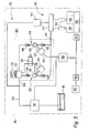
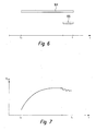
- the motor vehicle 110 is stopped and the internal combustion engine 114 is switched off, this then starts the electric fuel pump 118, which acts as a pre-feed pump, and the electric motor 154 of the electrically driven high-pressure fuel pump 124 (bar 164 in FIG. 7).
- fuel from the fuel tank 116 is precompressed (usually to approximately 4 to 8 bar) via the electric fuel pump 118 and conveyed to the electrically driven high-pressure fuel pump 124 via the pressure damper 130.
- the fuel is further compressed and in the fuel manifold 142 promoted. In this will the fuel is stored under very high pressure.
- the electrically powered High pressure fuel pump 124 only a small one Conveying capacity, which makes it very small. Due to the available time between actuation of the Switch 160 and starting the engine 114 (usually a few seconds) the conveying capacity of the electrically driven high pressure fuel pump 124 however, out to one in the fuel rail 142 desired high pressure fuel (possibly up to a few hundred bar) (see FIG. 7).
- Such high pressure fuel is desired to also at the first fuel injections through the Injectors 144 into the combustion chambers 146 of the internal combustion engine 114 to achieve good atomization of the fuel. This means that even with the first burns of Fuel in the combustion chambers 146 a good emission and Consumption behavior of internal combustion engine 114 achieved.
- the accumulator volume of the fuel rail 142 is chosen so that despite the low Delivery rate of the electrically driven high-pressure fuel pump 124 or even with already again high pressure fuel pump 124 turned off it is ensured that for a start of the Internal combustion engine, even under cold start conditions, required amount of fuel with sufficient pressure into the combustion chambers 146 of the internal combustion engine 114 can be introduced.
- the position of the crankshaft 145 is communicated to the control and regulating device 158 via the sensor 147 during the starting process of the internal combustion engine 114. After two full rotations of the crankshaft 145 (bar 166 in FIG. 2), the electric motor 154 of the electrically driven high-pressure fuel pump 124 is switched off by the control and regulating device 158 (time t 1 in FIG. 6).
- the internal combustion engine 114 has started, and on the other hand, it can also be assumed from this point in time that the delivery capacity of the high-pressure fuel pump 122 mechanically driven by the camshaft 140 of the internal combustion engine 114 is sufficient by the to provide the high-pressure fuel required in the fuel rail 142 for the further operation of the internal combustion engine 114.
- fuel injection is initiated by injectors 144.
- the fuel pressure can also be set by appropriately setting a drive frequency of the electric motor 154.
- Unit 120 By integrating the mechanically driven High pressure fuel pump 122 and the electric driven high pressure fuel pump 124 into one Assembly 120 with a common housing 120 can do this Unit 120 simply into the internal combustion engine 114 to be built in. Unit 120 only supports two Connections, namely the low pressure port 128 and the High pressure connection 141. Because the electrical driven high pressure fuel pump 124 only a small one Has conveying capacity and comparatively small, also builds the unit 120 comparatively small.
Landscapes
- Engineering & Computer Science (AREA)
- Chemical & Material Sciences (AREA)
- Combustion & Propulsion (AREA)
- Mechanical Engineering (AREA)
- General Engineering & Computer Science (AREA)
- Physics & Mathematics (AREA)
- Electromagnetism (AREA)
- Fuel-Injection Apparatus (AREA)
- Electrical Control Of Air Or Fuel Supplied To Internal-Combustion Engine (AREA)
Applications Claiming Priority (4)
| Application Number | Priority Date | Filing Date | Title |
|---|---|---|---|
| DE10232586 | 2002-07-18 | ||
| DE10232586 | 2002-07-18 | ||
| DE10255728A DE10255728A1 (de) | 2002-07-18 | 2002-11-29 | Kraftstoffsystem für eine Brennkraftmaschine sowie Kraftfahrzeug |
| DE10255728 | 2002-11-29 |
Publications (2)
| Publication Number | Publication Date |
|---|---|
| EP1382835A2 true EP1382835A2 (fr) | 2004-01-21 |
| EP1382835A3 EP1382835A3 (fr) | 2005-06-08 |
Family
ID=29781092
Family Applications (1)
| Application Number | Title | Priority Date | Filing Date |
|---|---|---|---|
| EP03013606A Withdrawn EP1382835A3 (fr) | 2002-07-18 | 2003-06-16 | Système de carburant pour un moteur à combustion interne ainsi qu'un véhicule |
Country Status (1)
| Country | Link |
|---|---|
| EP (1) | EP1382835A3 (fr) |
Citations (6)
| Publication number | Priority date | Publication date | Assignee | Title |
|---|---|---|---|---|
| US5884597A (en) * | 1996-06-20 | 1999-03-23 | Hitachi, Ltd. | Fuel feeding apparatus for internal combustion engine and vehicle using the fuel feeding apparatus |
| DE19753155A1 (de) * | 1997-11-29 | 1999-06-02 | Mannesmann Rexroth Ag | Kraftstoffversorgungssystem für eine Brennkraftmaschine und darin verwendete Hochdruckpumpe |
| DE19939051A1 (de) * | 1999-08-18 | 2001-02-22 | Volkswagen Ag | Vorrichtung und Verfahren zur Erzeugung eines Kraftstoffhochdrucks |
| US6234128B1 (en) * | 2000-03-13 | 2001-05-22 | General Motors Corporation | Fuel accumulator with pressure on demand |
| DE10144333A1 (de) * | 2000-09-11 | 2002-03-28 | Toyota Motor Co Ltd | Hochdruckkraftstoffzufuhrsystem |
| WO2002099264A1 (fr) * | 2001-06-06 | 2002-12-12 | Robert Bosch Gmbh | Procede, programme informatique et organe de commande et/ou de reglage pour le fonctionnement d'un moteur a combustion interne et systeme de carburant pour un moteur a combustion interne |
-
2003
- 2003-06-16 EP EP03013606A patent/EP1382835A3/fr not_active Withdrawn
Patent Citations (6)
| Publication number | Priority date | Publication date | Assignee | Title |
|---|---|---|---|---|
| US5884597A (en) * | 1996-06-20 | 1999-03-23 | Hitachi, Ltd. | Fuel feeding apparatus for internal combustion engine and vehicle using the fuel feeding apparatus |
| DE19753155A1 (de) * | 1997-11-29 | 1999-06-02 | Mannesmann Rexroth Ag | Kraftstoffversorgungssystem für eine Brennkraftmaschine und darin verwendete Hochdruckpumpe |
| DE19939051A1 (de) * | 1999-08-18 | 2001-02-22 | Volkswagen Ag | Vorrichtung und Verfahren zur Erzeugung eines Kraftstoffhochdrucks |
| US6234128B1 (en) * | 2000-03-13 | 2001-05-22 | General Motors Corporation | Fuel accumulator with pressure on demand |
| DE10144333A1 (de) * | 2000-09-11 | 2002-03-28 | Toyota Motor Co Ltd | Hochdruckkraftstoffzufuhrsystem |
| WO2002099264A1 (fr) * | 2001-06-06 | 2002-12-12 | Robert Bosch Gmbh | Procede, programme informatique et organe de commande et/ou de reglage pour le fonctionnement d'un moteur a combustion interne et systeme de carburant pour un moteur a combustion interne |
Also Published As
| Publication number | Publication date |
|---|---|
| EP1382835A3 (fr) | 2005-06-08 |
Similar Documents
| Publication | Publication Date | Title |
|---|---|---|
| DE10064055B4 (de) | Steuervorrichtung für Hochdruck-Kraftstoffpumpe und für Motor mit Direkteinspritzung | |
| EP2217795B1 (fr) | Système d'injection de carburant pour un moteur à combustion interne à injecteur de hc | |
| WO2001086139A1 (fr) | Procede de fonctionnement d'un systeme de dosage de carburant d'un moteur a combustion interne a injection directe | |
| EP2906803B1 (fr) | Procédé et dispositif permettant de faire fonctionner un moteur à combustion interne | |
| EP1296060A2 (fr) | Système d'injection de carburant pour un moteur à combustion interne | |
| EP1144851A1 (fr) | Systeme d'injection de carburant | |
| DE102007000311A1 (de) | Sammlerkraftstoffeinspritzvorrichtung zum Mindern einer Überdruckbeaufschlagung eines Sammlers | |
| DE102010039207A1 (de) | Kraftstoffeinspritzsystem einer Brennkraftmaschine | |
| EP1327766B1 (fr) | Procédé, programme informatique et dispositif de commande et/ou de réglage pour le fonctionnement d'un moteur à combustion interne, ainsi qu'un moteur à combustion interne | |
| DE102009028739A1 (de) | Schnellstart eines Common Rail-Systems | |
| EP1306553A2 (fr) | Pompe à carburant, système de distribution, procédé d'exploitation dudit système et moteur à combustion interne | |
| DE19753072C2 (de) | Kraftstoffversorgungssystem für eine Brennkraftmaschine insbesondere eines Kraftfahrzeugs | |
| DE10237586A1 (de) | Kraftstoffeinspritzeinrichtung für eine Brennkraftmaschine | |
| WO2001053691A1 (fr) | Systeme d'injection | |
| EP1109999B1 (fr) | Procede permettant la montee rapide de la pression de carburant dans un accumulateur de carburant | |
| DE19941850B4 (de) | Einspritzanlage für eine Brennkraftmaschine | |
| EP1382835A2 (fr) | Système de carburant pour un moteur à combustion interne ainsi qu'un véhicule | |
| DE10130352A1 (de) | Einspritzanlage für eine Brennkraftmaschine mit zwei Niederdruckpumpen | |
| DE10315318A1 (de) | Verfahren zum Betreiben einer Brennkraftmaschine | |
| DE10255728A1 (de) | Kraftstoffsystem für eine Brennkraftmaschine sowie Kraftfahrzeug | |
| DE19859175A1 (de) | Verfahren zum Entlüften eines Kraftstoffversorgungssystems | |
| DE10313133B3 (de) | Anordnung zum Überwachen von Betriebsparametern in einem Verbrennungsmotor | |
| DE102009061750B3 (de) | Schnellstart eines Common Rail-Systems | |
| EP1238190B1 (fr) | Procede pour ameliorer le demarrage d'un moteur a combustion interne equipe d'un systeme d'injection haute pression | |
| DE19843940A1 (de) | Kraftstoffeinspritzsystem |
Legal Events
| Date | Code | Title | Description |
|---|---|---|---|
| PUAI | Public reference made under article 153(3) epc to a published international application that has entered the european phase |
Free format text: ORIGINAL CODE: 0009012 |
|
| AK | Designated contracting states |
Kind code of ref document: A2 Designated state(s): AT BE BG CH CY CZ DE DK EE ES FI FR GB GR HU IE IT LI LU MC NL PT RO SE SI SK TR |
|
| AX | Request for extension of the european patent |
Extension state: AL LT LV MK |
|
| RIC1 | Information provided on ipc code assigned before grant |
Ipc: 7F 02M 59/44 B Ipc: 7F 02M 59/42 B Ipc: 7F 02M 59/08 B Ipc: 7F 02M 59/02 B Ipc: 7F 02M 37/18 A |
|
| PUAL | Search report despatched |
Free format text: ORIGINAL CODE: 0009013 |
|
| AK | Designated contracting states |
Kind code of ref document: A3 Designated state(s): AT BE BG CH CY CZ DE DK EE ES FI FR GB GR HU IE IT LI LU MC NL PT RO SE SI SK TR |
|
| AX | Request for extension of the european patent |
Extension state: AL LT LV MK |
|
| AKX | Designation fees paid | ||
| STAA | Information on the status of an ep patent application or granted ep patent |
Free format text: STATUS: THE APPLICATION IS DEEMED TO BE WITHDRAWN |
|
| 18D | Application deemed to be withdrawn |
Effective date: 20051209 |
|
| REG | Reference to a national code |
Ref country code: DE Ref legal event code: 8566 |