EP1382485A2 - Ascher oder dgl. Behältnis - Google Patents
Ascher oder dgl. Behältnis Download PDFInfo
- Publication number
- EP1382485A2 EP1382485A2 EP03010027A EP03010027A EP1382485A2 EP 1382485 A2 EP1382485 A2 EP 1382485A2 EP 03010027 A EP03010027 A EP 03010027A EP 03010027 A EP03010027 A EP 03010027A EP 1382485 A2 EP1382485 A2 EP 1382485A2
- Authority
- EP
- European Patent Office
- Prior art keywords
- lever
- transmission element
- container shell
- housing
- pivot lever
- Prior art date
- Legal status (The legal status is an assumption and is not a legal conclusion. Google has not performed a legal analysis and makes no representation as to the accuracy of the status listed.)
- Granted
Links
Images


Classifications
-
- B—PERFORMING OPERATIONS; TRANSPORTING
- B60—VEHICLES IN GENERAL
- B60N—SEATS SPECIALLY ADAPTED FOR VEHICLES; VEHICLE PASSENGER ACCOMMODATION NOT OTHERWISE PROVIDED FOR
- B60N3/00—Arrangements or adaptations of other passenger fittings, not otherwise provided for
- B60N3/08—Arrangements or adaptations of other passenger fittings, not otherwise provided for of receptacles for refuse, e.g. ash-trays
- B60N3/083—Ash-trays
Definitions
- the invention relates to an ashtray or the like.
- Container in particular for vehicles, with a receiving housing and one removably inserted in the receiving housing Container shell, whereby to lift the container shell from a position of use in a convenient removal position a lifting mechanism is provided, which on Receiving housing slidably mounted actuator and a with this cooperating transmission element comprises.
- An ashtray for vehicles is known from DE 44 27 868 C2, the Removable container shell used in the receiving housing by means of a Lifting mechanism from a position of use in a convenient removal position is relocatable.
- the lifting mechanism comprises a receptacle housing slidably mounted actuator that with a by a slide formed transmission element is in operative connection.
- a slide formed transmission element is in operative connection.
- an inclined surface is provided, which by moving the slide in contact with a corresponding oblique attack surface of the container shell reaches.
- the object of the invention is an alternative lifting mechanism for a removable To create an ashtray container shell that has a simple, inexpensive construction having.
- the transmission element can be designed as a lever, as a linkage, as a slide or the like his.
- the relatively short swivel lever is vertical at its lower end region Wall of the receiving housing rotatably mounted. At a distance from this articulation an area of the transmission element facing away from the actuating element Swivel lever.
- this protruding pin arranged with a circular slot opening of the Receiving housing is in operative connection. Due to the cam-shaped design of the upper edge area of the pivot lever is a simple lifting of the Container shell achieved.
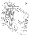
- ashtray 1 is in the dashboard or on a console of a vehicle arranged ashtray 1 shown, which consists of a housing-attached housing 2 and an ashtray insert 3 guided in a drawer-like manner in the housing 2.
- the ashtray insert 3 formed by an injection molded part made of plastic is not specified in detail shown side guides from a closed position, not shown in a extended position A acc. 1 to 4 relocatable and vice versa.
- the Ashtray insert 3 comprises a receptacle housing 4, from above or from the side a removable container shell 5 can be used. Laterally next to the container shell 5, a cigarette lighter 6 is provided.
- To passenger compartment 7 that is Provide housing 3 with a decorative panel 8.
- a lifting mechanism 9 is provided, the consists of an actuating element 10 slidably mounted on the receiving housing 4, a transmission element 11 and a pivot lever 12 is composed.
- the lifting mechanism 9 works in such a way that when moving the Actuator 10 in the direction of arrow R (in the vehicle transverse direction) of the pivot lever 12 exercises an arcuate movement, in the course of which the rounded upper End portion 13 of the pivot lever 12 in contact with the bottom 14 of the Container shell 5 arrives and this upwards in the convenient removal position C. emotional.
- the actuating element 10 is arranged laterally next to the container shell 5 in front of the cigarette lighter 6.
- On a flat, approximately horizontal Wall 15 of the receiving housing 4 is a straight transverse Slot opening 16 formed to guide the actuator 10 during serves the displacement movement.
- the actuator 10 penetrates the Slot opening 16 and extends both above and below the wall 15.
- the area of the actuating element 10 running below the wall 15 is with the end of the transmission element 11 facing away from the pivot lever 12 connected.
- the actuating element 10 takes the Position D. 3 and 4, the transmission element 11 is a slide 18th formed on a bottom wall 19 and the vertical front wall 20 of the Receiving housing 4 is guided displaceably in the transverse direction.
- the transmission element 11 can, however, also be designed as a lever 21,. As a rod or the like.
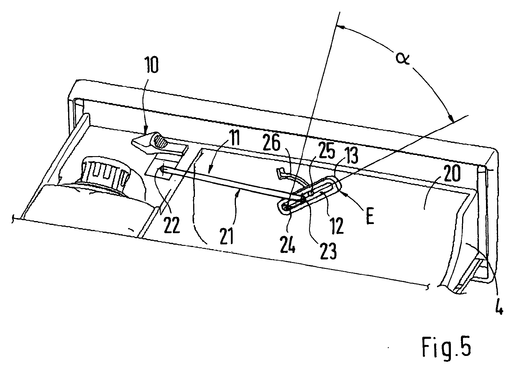
- An easy one formed transmission element 11 is shown in Fig. 5.
- One end 22 of the lever 21 is articulated to the actuating element 10, whereas the other End 23 is directly connected to the pivot lever 12.
- the one in upright Directionally extending pivot lever 12 is with its lower end portion 24 by one axis running in the vehicle longitudinal direction with the inside of the upright wall 20 of the receiving housing 4 connected.
- the pivot lever 12 articulated with the one located above Transmission element 11 connected.
- the upper edge region 13 of the pivot lever 12 has a rounded shape. It is preferably cam-shaped to have a to ensure good power transmission. For precise guidance of the swivel lever 12 during its pivoting movement, this locally has a protruding pin 25 on the one formed on the upright wall 20 of the receiving housing 4 arcuate slot opening 26 is engaged.
- the pivot lever 12 takes the position E (Fig. 1 and 3). there the upper edge region 13 of the pivot lever 12 runs at a short distance from overlying laterally parked edge flange 27 of the container shell 5.
- Das Actuator is in position D.
- the actuating element 10 in Vehicle transverse direction in the direction of arrow R moved to position F (Fig. 4).
- the transmission element 11 also a longitudinal movement in the direction of arrow R and the pivot lever 12 is pivoted counterclockwise by the angle ⁇ in a position G (Fig. 4).
- the upper edge region 13 reaches during the circular pivoting by the angle ⁇ in contact with the bottom 14 of the edge flange 27 of the container shell 5 and lifts it by a defined amount the removal position C at (Fig. 2).
Landscapes
- Engineering & Computer Science (AREA)
- Transportation (AREA)
- Mechanical Engineering (AREA)
- Passenger Equipment (AREA)
Abstract
Description
Es zeigen
- Fig. 1
- eine Seitenansicht auf einen Ascher mit ausgefahrenem Aufnahmegehäuse und einer eingesetzten Behälterschale in Gebrauchslage,
- Fig. 2
- eine Ansicht ähnlich Fig. 1 mit der Behälterschale in der angehobenen griffgünstigen Entnahmeposition,
- Fig. 3
- eine perspektivische Ansicht auf die Aushebemechanik in Gebrauchslage der Behälterschale,
- Fig. 4
- eine Ansicht auf die Aushebemechanik in der Entnahmeposition der Behälterschale.
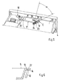
- Fig. 5
- eine Ansicht auf eine zweite Ausführungsform einer Aushebemechanik und
- Fig. 6
- einen Schnitt durch den Randbereich der Behälterschale und die darunterliegende Aushebemechanik.
Claims (7)
- Ascher oder dgl. Behältnis, insbesondere für Fahrzeuge, mit einem Aufnahmegehäuse und einer im Aufnahmegehäuse herausnehmbar eingesetzten Behälterschale, wobei zum Anheben der Behälterschale von einer Gebrauchslage in eine griffgünstige Entnahmeposition eine Aushebemechanik vorgesehen ist, die ein am Aufnahmegehäuse verschiebbar gelagertes Betätigungselement und ein mit diesem zusammenwirkendes Übertragungselement umfaßt, dadurch gekennzeichnet, daß das Übertragungselement (11) mit einem am Aufnahmegehäuse (4) drehbar gelagerten Schwenkhebel (12) in Wirkverbindung steht, dergestalt, daß beim Verschieben des Betätigungselementes (10) der Schwenkhebel (12) eine kreisbogenförmige Bewegung ausübt, in deren Verlauf der gerundete obere Endbereich (13) des Schwenkhebels (12) in Kontakt mit der Unterseite (14) der Behälterschale (5) gelangt und diese nach oben hin in die griffgünstige Entnahmeposition (C) bewegt.
- Ascher nach Anspruch 1, dadurch gekennzeichnet, daß der Schwenkhebel (12) an seinem unteren Endbereich (24) drehbar mit dem Aufnahmegehäuse (4) verbunden ist.
- Ascher nach Anspruch 1, dadurch gekennzeichnet, daß der Schwenkhebel (12) entfernt von seiner aufnahmegehäuseseitigen Anlenkung gelenkig mit dem Übertragungselement (11) verbunden ist.
- Ascher nach Anspruch 1, dadurch gekennzeichnet, daß das Übertragungselement (11) durch einen Hebel (21), ein Gestänge, einen Schieber (18) oder dgl. gebildet ist.
- Ascher nach Anspruch 1, dadurch gekennzeichnet, daß der obere Endbereich (13) des Schwenkhebels (12) nockenförmig ausgebildet ist.
- Ascher nach Anspruch 1, dadurch gekennzeichnet, daß der obere Endbereich (13) des Schwenkhebels (12) beim Anheben mit der Unterseite (14) eines seitlich abgestellten randseitigen Flansches (27) der Behälterschale (5) zusammenwirkt.
- Ascher nach Anspruch 1, dadurch gekennzeichnet, daß der Schwenkhebel (12) örtlich einen vorstehenden Zapfen (25) aufweist, der mit einer am Aufnahmegehäuse (4) ausgebildeten kreisbogenförmigen Schlitzöffnung (26) zusammenwirkt.
Applications Claiming Priority (2)
| Application Number | Priority Date | Filing Date | Title |
|---|---|---|---|
| DE10232600A DE10232600B3 (de) | 2002-07-18 | 2002-07-18 | Ascher oder dgl. Behältnis |
| DE10232600 | 2002-07-18 |
Publications (3)
| Publication Number | Publication Date |
|---|---|
| EP1382485A2 true EP1382485A2 (de) | 2004-01-21 |
| EP1382485A3 EP1382485A3 (de) | 2005-01-05 |
| EP1382485B1 EP1382485B1 (de) | 2010-07-14 |
Family
ID=29762039
Family Applications (1)
| Application Number | Title | Priority Date | Filing Date |
|---|---|---|---|
| EP03010027A Expired - Lifetime EP1382485B1 (de) | 2002-07-18 | 2003-05-02 | Ascher oder dgl. Behältnis |
Country Status (3)
| Country | Link |
|---|---|
| US (1) | US7163116B2 (de) |
| EP (1) | EP1382485B1 (de) |
| DE (2) | DE10232600B3 (de) |
Cited By (1)
| Publication number | Priority date | Publication date | Assignee | Title |
|---|---|---|---|---|
| DE102009057552A1 (de) * | 2009-12-09 | 2011-06-16 | Dr. Ing. H.C. F. Porsche Aktiengesellschaft | Anhebevorrichtung |
Families Citing this family (3)
| Publication number | Priority date | Publication date | Assignee | Title |
|---|---|---|---|---|
| US7195147B2 (en) * | 2003-10-03 | 2007-03-27 | Kenneth Neil Price | Portable promotional ashtray |
| US20070003670A1 (en) * | 2005-06-29 | 2007-01-04 | Rod Jendrysik | Sports drink acid blend to reduce or eliminate aftertaste |
| US7980416B2 (en) * | 2007-06-27 | 2011-07-19 | Toyota Motor Engineering & Manufacturing North America, Inc. | Vehicle storage bin |
Family Cites Families (9)
| Publication number | Priority date | Publication date | Assignee | Title |
|---|---|---|---|---|
| US1820555A (en) * | 1929-01-05 | 1931-08-25 | Metal Package Corp | Waste receptacle |
| US1842654A (en) * | 1930-05-26 | 1932-01-26 | Brandt Albrecht | Cigar support and ash tray |
| US1880752A (en) * | 1931-10-07 | 1932-10-04 | Brandt Albrect | Ash tray and cigar rest |
| US2559361A (en) * | 1948-08-25 | 1951-07-03 | Chicago Metallic Mfg Company | Receptacle closure |
| US2946474A (en) * | 1958-08-04 | 1960-07-26 | Knapp Monarch Co | Sanitary garbage receiver |
| US4799604A (en) * | 1987-08-05 | 1989-01-24 | Yoshida Industry Co., Ltd. | Vanity case |
| US4927108A (en) * | 1989-07-13 | 1990-05-22 | Chrysler Corporation | Cup holder |
| DE4421666C1 (de) * | 1994-06-23 | 1995-06-14 | Happich Gmbh Gebr | Ascher od. dgl. Behältnis, insbesondere für Fahrzeuge |
| DE4427868C2 (de) * | 1994-08-06 | 1997-12-18 | Happich Gmbh Gebr | Behältnis, insbesondere Ascher für Fahrzeuge |
-
2002
- 2002-07-18 DE DE10232600A patent/DE10232600B3/de not_active Expired - Fee Related
-
2003
- 2003-05-02 EP EP03010027A patent/EP1382485B1/de not_active Expired - Lifetime
- 2003-05-02 DE DE50312877T patent/DE50312877D1/de not_active Expired - Lifetime
- 2003-07-18 US US10/622,137 patent/US7163116B2/en not_active Expired - Fee Related
Cited By (2)
| Publication number | Priority date | Publication date | Assignee | Title |
|---|---|---|---|---|
| DE102009057552A1 (de) * | 2009-12-09 | 2011-06-16 | Dr. Ing. H.C. F. Porsche Aktiengesellschaft | Anhebevorrichtung |
| DE102009057552B4 (de) | 2009-12-09 | 2022-09-01 | Dr. Ing. H.C. F. Porsche Aktiengesellschaft | Anhebevorrichtung |
Also Published As
| Publication number | Publication date |
|---|---|
| US7163116B2 (en) | 2007-01-16 |
| DE50312877D1 (de) | 2010-08-26 |
| DE10232600B3 (de) | 2004-03-04 |
| EP1382485A3 (de) | 2005-01-05 |
| EP1382485B1 (de) | 2010-07-14 |
| US20040094547A1 (en) | 2004-05-20 |
Similar Documents
| Publication | Publication Date | Title |
|---|---|---|
| DE4443521C1 (de) | Abdeckbarer Behälter für Fahrzeuge | |
| EP0846584B1 (de) | Verdeckkastendeckel für ein Kraftfahrzeug | |
| DE3807880C2 (de) | ||
| DE3345122C2 (de) | Fahrzeugschiebedach | |
| EP0842821A2 (de) | Armlehne für Kraftfahrzeugsitze mit einem Ablagefach für ein Zusatzgerät | |
| DE4440814A1 (de) | Verschiebbare Klappe, insbesondere Tankklappe eines Kraftfahrzeugs | |
| DE19811783C1 (de) | Abdeckbarer Behälter | |
| EP1284216A2 (de) | Mittelkonsole | |
| EP0764558A2 (de) | Einbau-Vorrichtung für Fahrzeuge | |
| EP0184620A2 (de) | Verstauvorrichtung innerhalb von Verkleidungen in Kraftfahrzeugen | |
| DE3913567A1 (de) | Windabweiser fuer kraftfahrzeuge | |
| DE9406929U1 (de) | Dachfenster | |
| DE10065947C2 (de) | Öffnungsfähiges Fahrzeugdach | |
| EP0352434A2 (de) | Ascher, insbesondere für Fahrzeuge | |
| DE10232600B3 (de) | Ascher oder dgl. Behältnis | |
| DE19634324C2 (de) | Fahrzeugdach | |
| DE4001759C1 (en) | Sun roof for motor vehicles - has lever pivoting at end of sliding guide to actuate roof panel | |
| EP0733512B1 (de) | Behälter, wie Ascher, Ablagefach oder dgl. insbesondere für Fahrzeuge | |
| DE4407522C1 (de) | Verriegelungsvorrichtung für einen schwenkbar gelagerten Aufbewahrungsbehälter in einem Fahrzeug | |
| DE3732548A1 (de) | Ausstell-schiebedach fuer kraftfahrzeuge | |
| DE10039305A1 (de) | Führungsmechanismus für eine Abdeckplatte eines Ablagefachs in einem Fahrzeug | |
| DE3232607A1 (de) | Schliessvorrichtung fuer klappen, insbesondere an kraftfahrzeugen | |
| EP0936131B1 (de) | Kippvorrichtung für abgefederte Fahrerhäuser von Nutzfahrzeugen | |
| DE4427868C2 (de) | Behältnis, insbesondere Ascher für Fahrzeuge | |
| DE2133969A1 (de) | Mit einem starren Deckel versehener, in eine Wand eingelassener Behälter, insbesondere Aschenbecher für Kraftfahrzeuge |
Legal Events
| Date | Code | Title | Description |
|---|---|---|---|
| PUAI | Public reference made under article 153(3) epc to a published international application that has entered the european phase |
Free format text: ORIGINAL CODE: 0009012 |
|
| AK | Designated contracting states |
Kind code of ref document: A2 Designated state(s): AT BE BG CH CY CZ DE DK EE ES FI FR GB GR HU IE IT LI LU MC NL PT RO SE SI SK TR |
|
| AX | Request for extension of the european patent |
Extension state: AL LT LV MK |
|
| PUAL | Search report despatched |
Free format text: ORIGINAL CODE: 0009013 |
|
| AK | Designated contracting states |
Kind code of ref document: A3 Designated state(s): AT BE BG CH CY CZ DE DK EE ES FI FR GB GR HU IE IT LI LU MC NL PT RO SE SI SK TR |
|
| AX | Request for extension of the european patent |
Extension state: AL LT LV MK |
|
| 17P | Request for examination filed |
Effective date: 20050705 |
|
| AKX | Designation fees paid |
Designated state(s): DE ES FR GB IT SE |
|
| 17Q | First examination report despatched |
Effective date: 20071010 |
|
| RAP1 | Party data changed (applicant data changed or rights of an application transferred) |
Owner name: DR. ING. H.C. F. PORSCHE AKTIENGESELLSCHAFT |
|
| RAP1 | Party data changed (applicant data changed or rights of an application transferred) |
Owner name: DR. ING. H.C. F. PORSCHE AKTIENGESELLSCHAFT |
|
| GRAP | Despatch of communication of intention to grant a patent |
Free format text: ORIGINAL CODE: EPIDOSNIGR1 |
|
| RAP1 | Party data changed (applicant data changed or rights of an application transferred) |
Owner name: DR. ING. H.C. F. PORSCHE AG |
|
| GRAS | Grant fee paid |
Free format text: ORIGINAL CODE: EPIDOSNIGR3 |
|
| GRAA | (expected) grant |
Free format text: ORIGINAL CODE: 0009210 |
|
| AK | Designated contracting states |
Kind code of ref document: B1 Designated state(s): DE ES FR GB IT SE |
|
| REG | Reference to a national code |
Ref country code: GB Ref legal event code: FG4D Free format text: NOT ENGLISH |
|
| REF | Corresponds to: |
Ref document number: 50312877 Country of ref document: DE Date of ref document: 20100826 Kind code of ref document: P |
|
| REG | Reference to a national code |
Ref country code: FR Ref legal event code: TP |
|
| PG25 | Lapsed in a contracting state [announced via postgrant information from national office to epo] |
Ref country code: SE Free format text: LAPSE BECAUSE OF FAILURE TO SUBMIT A TRANSLATION OF THE DESCRIPTION OR TO PAY THE FEE WITHIN THE PRESCRIBED TIME-LIMIT Effective date: 20100714 |
|
| PLBE | No opposition filed within time limit |
Free format text: ORIGINAL CODE: 0009261 |
|
| STAA | Information on the status of an ep patent application or granted ep patent |
Free format text: STATUS: NO OPPOSITION FILED WITHIN TIME LIMIT |
|
| 26N | No opposition filed |
Effective date: 20110415 |
|
| PG25 | Lapsed in a contracting state [announced via postgrant information from national office to epo] |
Ref country code: ES Free format text: LAPSE BECAUSE OF FAILURE TO SUBMIT A TRANSLATION OF THE DESCRIPTION OR TO PAY THE FEE WITHIN THE PRESCRIBED TIME-LIMIT Effective date: 20101025 |
|
| REG | Reference to a national code |
Ref country code: DE Ref legal event code: R097 Ref document number: 50312877 Country of ref document: DE Effective date: 20110415 |
|
| PGFP | Annual fee paid to national office [announced via postgrant information from national office to epo] |
Ref country code: GB Payment date: 20140521 Year of fee payment: 12 |
|
| PGFP | Annual fee paid to national office [announced via postgrant information from national office to epo] |
Ref country code: DE Payment date: 20140424 Year of fee payment: 12 Ref country code: FR Payment date: 20140527 Year of fee payment: 12 Ref country code: IT Payment date: 20140530 Year of fee payment: 12 |
|
| REG | Reference to a national code |
Ref country code: DE Ref legal event code: R119 Ref document number: 50312877 Country of ref document: DE |
|
| GBPC | Gb: european patent ceased through non-payment of renewal fee |
Effective date: 20150502 |
|
| PG25 | Lapsed in a contracting state [announced via postgrant information from national office to epo] |
Ref country code: IT Free format text: LAPSE BECAUSE OF NON-PAYMENT OF DUE FEES Effective date: 20150502 |
|
| REG | Reference to a national code |
Ref country code: FR Ref legal event code: ST Effective date: 20160129 |
|
| PG25 | Lapsed in a contracting state [announced via postgrant information from national office to epo] |
Ref country code: GB Free format text: LAPSE BECAUSE OF NON-PAYMENT OF DUE FEES Effective date: 20150502 Ref country code: DE Free format text: LAPSE BECAUSE OF NON-PAYMENT OF DUE FEES Effective date: 20151201 |
|
| PG25 | Lapsed in a contracting state [announced via postgrant information from national office to epo] |
Ref country code: FR Free format text: LAPSE BECAUSE OF NON-PAYMENT OF DUE FEES Effective date: 20150601 |