EP1382379A2 - Wirbelgenerator mit kontrollierter Nachlaufströmung - Google Patents
Wirbelgenerator mit kontrollierter Nachlaufströmung Download PDFInfo
- Publication number
- EP1382379A2 EP1382379A2 EP03405505A EP03405505A EP1382379A2 EP 1382379 A2 EP1382379 A2 EP 1382379A2 EP 03405505 A EP03405505 A EP 03405505A EP 03405505 A EP03405505 A EP 03405505A EP 1382379 A2 EP1382379 A2 EP 1382379A2
- Authority
- EP
- European Patent Office
- Prior art keywords
- flow
- vortex generator
- vortex
- wake
- side surfaces
- Prior art date
- Legal status (The legal status is an assumption and is not a legal conclusion. Google has not performed a legal analysis and makes no representation as to the accuracy of the status listed.)
- Granted
Links
Images


Classifications
-
- F—MECHANICAL ENGINEERING; LIGHTING; HEATING; WEAPONS; BLASTING
- F15—FLUID-PRESSURE ACTUATORS; HYDRAULICS OR PNEUMATICS IN GENERAL
- F15D—FLUID DYNAMICS, i.e. METHODS OR MEANS FOR INFLUENCING THE FLOW OF GASES OR LIQUIDS
- F15D1/00—Influencing flow of fluids
- F15D1/02—Influencing flow of fluids in pipes or conduits
-
- B—PERFORMING OPERATIONS; TRANSPORTING
- B01—PHYSICAL OR CHEMICAL PROCESSES OR APPARATUS IN GENERAL
- B01F—MIXING, e.g. DISSOLVING, EMULSIFYING OR DISPERSING
- B01F25/00—Flow mixers; Mixers for falling materials, e.g. solid particles
- B01F25/30—Injector mixers
- B01F25/31—Injector mixers in conduits or tubes through which the main component flows
- B01F25/313—Injector mixers in conduits or tubes through which the main component flows wherein additional components are introduced in the centre of the conduit
- B01F25/3131—Injector mixers in conduits or tubes through which the main component flows wherein additional components are introduced in the centre of the conduit with additional mixing means other than injector mixers, e.g. screens, baffles or rotating elements
-
- B—PERFORMING OPERATIONS; TRANSPORTING
- B01—PHYSICAL OR CHEMICAL PROCESSES OR APPARATUS IN GENERAL
- B01F—MIXING, e.g. DISSOLVING, EMULSIFYING OR DISPERSING
- B01F25/00—Flow mixers; Mixers for falling materials, e.g. solid particles
- B01F25/40—Static mixers
- B01F25/42—Static mixers in which the mixing is affected by moving the components jointly in changing directions, e.g. in tubes provided with baffles or obstructions
- B01F25/43—Mixing tubes, e.g. wherein the material is moved in a radial or partly reversed direction
- B01F25/431—Straight mixing tubes with baffles or obstructions that do not cause substantial pressure drop; Baffles therefor
- B01F25/4317—Profiled elements, e.g. profiled blades, bars, pillars, columns or chevrons
- B01F25/43171—Profiled blades, wings, wedges, i.e. plate-like element having one side or part thicker than the other
-
- B—PERFORMING OPERATIONS; TRANSPORTING
- B01—PHYSICAL OR CHEMICAL PROCESSES OR APPARATUS IN GENERAL
- B01F—MIXING, e.g. DISSOLVING, EMULSIFYING OR DISPERSING
- B01F25/00—Flow mixers; Mixers for falling materials, e.g. solid particles
- B01F25/40—Static mixers
- B01F25/42—Static mixers in which the mixing is affected by moving the components jointly in changing directions, e.g. in tubes provided with baffles or obstructions
- B01F25/43—Mixing tubes, e.g. wherein the material is moved in a radial or partly reversed direction
- B01F25/431—Straight mixing tubes with baffles or obstructions that do not cause substantial pressure drop; Baffles therefor
- B01F25/43197—Straight mixing tubes with baffles or obstructions that do not cause substantial pressure drop; Baffles therefor characterised by the mounting of the baffles or obstructions
- B01F25/431971—Mounted on the wall
-
- F—MECHANICAL ENGINEERING; LIGHTING; HEATING; WEAPONS; BLASTING
- F23—COMBUSTION APPARATUS; COMBUSTION PROCESSES
- F23C—METHODS OR APPARATUS FOR COMBUSTION USING FLUID FUEL OR SOLID FUEL SUSPENDED IN A CARRIER GAS OR AIR
- F23C7/00—Combustion apparatus characterised by arrangements for air supply
- F23C7/002—Combustion apparatus characterised by arrangements for air supply the air being submitted to a rotary or spinning motion
-
- F—MECHANICAL ENGINEERING; LIGHTING; HEATING; WEAPONS; BLASTING
- F23—COMBUSTION APPARATUS; COMBUSTION PROCESSES
- F23R—GENERATING COMBUSTION PRODUCTS OF HIGH PRESSURE OR HIGH VELOCITY, e.g. GAS-TURBINE COMBUSTION CHAMBERS
- F23R3/00—Continuous combustion chambers using liquid or gaseous fuel
- F23R3/02—Continuous combustion chambers using liquid or gaseous fuel characterised by the air-flow or gas-flow configuration
- F23R3/04—Air inlet arrangements
- F23R3/10—Air inlet arrangements for primary air
- F23R3/12—Air inlet arrangements for primary air inducing a vortex
-
- B—PERFORMING OPERATIONS; TRANSPORTING
- B01—PHYSICAL OR CHEMICAL PROCESSES OR APPARATUS IN GENERAL
- B01F—MIXING, e.g. DISSOLVING, EMULSIFYING OR DISPERSING
- B01F2215/00—Auxiliary or complementary information in relation with mixing
- B01F2215/04—Technical information in relation with mixing
- B01F2215/0413—Numerical information
- B01F2215/0436—Operational information
- B01F2215/044—Numerical composition values of components or mixtures, e.g. percentage of components
-
- F—MECHANICAL ENGINEERING; LIGHTING; HEATING; WEAPONS; BLASTING
- F05—INDEXING SCHEMES RELATING TO ENGINES OR PUMPS IN VARIOUS SUBCLASSES OF CLASSES F01-F04
- F05B—INDEXING SCHEME RELATING TO WIND, SPRING, WEIGHT, INERTIA OR LIKE MOTORS, TO MACHINES OR ENGINES FOR LIQUIDS COVERED BY SUBCLASSES F03B, F03D AND F03G
- F05B2260/00—Function
- F05B2260/20—Heat transfer, e.g. cooling
- F05B2260/221—Improvement of heat transfer
- F05B2260/222—Improvement of heat transfer by creating turbulence
Definitions
- the invention relates to a vortex generator in one of one fluid medium acted upon flow channel and a Process for controlling the wake flow of such Vortex generator.
- a particular field of application of the invention is the swirling and mixing of fuel / air mixtures in premix burners.
- Static mixers for shortening the mixing distance of flowing fluid media are known in a variety of designs.
- a design of such mixers, which allows an intensive mixing of flowing fluid media with a comparatively low pressure drop, is the subject of EP 0 623 786.
- the static mixers discussed here, hereinafter referred to as vortex generators represent tetrahedron-like bodies which have one of at least one lateral surface the fluid channel acted upon flow channel are arranged. They comprise three freely flowing active surfaces that extend in the direction of flow, a roof surface facing the flow channel and two side surfaces.
- the side surfaces connected to the wall of the flow duct enclose an arrow angle ⁇ with one another, whereas the roof surface runs at an angle of inclination ⁇ to the duct wall.
- the size and strength of the wake are functions of the element height h, the element length l, the angle of attack wink and the arrow angle ⁇ . Varying these parameters provides a simple means of aerodynamically stabilizing a flow. With relatively large angles of attack ⁇ and / or arrow angles ⁇ , the vortex strength of the wake vortices increases to such an extent that an area with low flow velocity forms in their core, which under changing flow conditions harbors the risk of a breakdown of the vortex with the formation of a backflow .
- the design of the vortex generators is therefore always a compromise, on the one hand, to make the vortices so strong that the components involved are mixed as quickly as possible in the wake, but on the other hand not to make the vortices so strong that an area of low flow velocity or is formed at the core even a backflow.
- the invention has for its object to provide a vortex generator, who avoids the disadvantages mentioned and the Formation of a backflow zone in the core of the wake vortex even under changing flow conditions in the flow channel excludes safely and thus allows use and expand variability of these vortex generators. Furthermore, the invention is based on the object Process for controlling the wake flow of such vortex generators provide.
- the basic idea of the invention is to increase the axial speed in the vortex core by specifically introducing an axial pulse into the core flow of the wake vortex.
- this axial impulse is introduced in the immediate area of the core flow by introducing a secondary flow oriented at least approximately in the flow direction.
- one of the components to be mixed is introduced into the flow channel as a secondary flow. It has proven to be advantageous to introduce the secondary flow into the core flow of the wake vortex via outlet openings on the vortex generator.
- the outlet openings of the secondary medium are expediently arranged in the region of the side surfaces of the vortex generator or on its downstream edge. According to a particularly favorable embodiment, the outlet opening is arranged half the chord length of the side surface below the trailing edge.
- the secondary flow can be introduced into the core flow from a single opening on the vortex generator or from a number of outlet openings which are aligned with the vortex core.
- the cooling bores arranged on or near the vortex generators be used in a targeted manner to introduce an additional axial pulse. This can be achieved by modifying part of the cooling bores in such a way that an increased axial pulse is introduced into the core flow of the wake vortices.
- the geometry of the outlet openings is configured accordingly, for example with regard to their orientation and / or their throughput.
- the measures according to the invention are also suitable as a retrofit measure for retrofitting already installed vortex generators according to the prior art by introducing appropriate outlet openings and providing means for supplying a secondary fluid into the hollow interior of the vortex generators.
- Vortex generators which are already equipped with means for supplying a secondary fluid and with outlet openings for cooling or admixing purposes, can be retrofitted with a modified design of the geometry of the outlet openings (FIGS. 4b; 5b). Since the amount of secondary fluid that can be fed in is variably adjustable, the invention allows to react actively to temporarily or permanently changed flow conditions.
- the mass flow of the secondary flow is very low. It is between 0.1% and 5%, in particular between 0.5% and 1.5%, based on the total mass flow.
- FIG. 1 and 2 show in principle the mode of operation of a vortex generator (2) acted upon by a flow (1) according to the prior art.
- a vortex generator (2) has three freely flowing surfaces in the direction of flow, two side surfaces (3) and (4) and perpendicularly a roof surface (5), the side surfaces (3) and (4) being a right-angled triangle and the roof surface (5) form an isosceles triangle.
- the side surfaces (3) and (4) are substantially perpendicular to the channel wall (6), without this being a mandatory requirement, and are preferably fixed gas-tight to one of their catheter sides on the channel wall (6).
- the side surfaces (3) and (4) are dimensioned essentially congruent.
- the roof surface (5) which assumes an acute angle of attack ⁇ with respect to the channel wall (6), is supported on the hypotenuse sides thereof, which are increasingly moving away from the channel wall (6) in the direction of flow. With a butt edge (8) running transversely to the direction of flow, it abuts the channel wall (6).
- the flush abutting edges between the two side surfaces (3) and (4) and the roof surface (5) form trailing edges (9) and (10).
- the axis of symmetry of the vortex generators (2) is aligned parallel to the direction of flow.
- the vortex generator (2) can also be provided with a bottom surface, with the aid of which it is fixed in a suitable manner on the channel wall (6).
- Such a floor area is, however, unrelated to the mode of operation of the vortex generator.
- the mode of operation of the vortex generator (2) is essentially the one set out below.
- a channel flow (1) flows towards the vortex generator (2) and is deflected by its roof surface (5).
- Fig.3 represents the basic principle of the highly schematic described solution.
- Starting from a suitable Place on the vortex generator (2) is in the wake vortex (11) an axial pulse was introduced to influence the core flow.
- a secondary flow (13) in the An additional impulse is generated near the vortex core, which through the inductive effect of the swirl flow in the area of the vortex core is drawn in.
- the impulse is directed parallel to the main flow, so the Vortex (11) and the wake flow is accelerated.
- the Vortex breakdown is delayed and postponed downstream.
- the vortex generator (2) with at least one Outlet opening (12) for a fluid medium in the area of Side surface (3) equipped.
- the outlet opening (12) is arranged and aligned in this way, for example in half chord length below the trailing edge (9) that the emerging fluid jet (13) in the core flow of the wake vortex (11) penetrates and the axial speed in reinforced this area.
- FIG 5 shows an alternative way of introducing a Secondary flow is shown schematically.
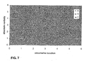
- Fig. 7 it is shown that despite acceleration of the vortex core the vortex strength is not weakened. Im auseke even up to 50% downstream of the vortex generator.
- the Varinate A represents the reference case of a vortex generator that is so heavily employed that there arises in the wake Area of low flow velocity.
- the variants B and C give the conditions for a vortex generator according to the invention again, in which a secondary current in half the chord length of one side surface (variant B) or on the downstream abutting edge (variant C) is applied.
- the vortex generators shown here (2) are arranged symmetrically and parallel to the direction of flow. Swirl-like vortices (11) are thus generated. Regardless of this, it is of course also within the framework the invention to design the vortex generators (2) asymmetrically, for example in the form of a half vortex generator, in which only one of the two side surfaces (3) or (4) fixed with an arrow angle ⁇ / 2 on the channel wall (6) whereas the other side surface (3) or (4) is parallel is aligned to the direction of flow. In contrast to the symmetrical Vortex generator (2) is used instead of one Pair of opposite vertebrae (11) only one trailing vertebra (11) generated on the arrowed side. As a result, the main flow (1) a spin imposed.
Landscapes
- Engineering & Computer Science (AREA)
- Chemical & Material Sciences (AREA)
- Mechanical Engineering (AREA)
- General Engineering & Computer Science (AREA)
- Chemical Kinetics & Catalysis (AREA)
- Combustion & Propulsion (AREA)
- Dispersion Chemistry (AREA)
- Physics & Mathematics (AREA)
- Fluid Mechanics (AREA)
- Percussion Or Vibration Massage (AREA)
- Gas Burners (AREA)
- Structures Of Non-Positive Displacement Pumps (AREA)
Abstract
Description
Eine Gestaltungsform derartiger Mischer, die eine intensive Vermischung strömender fluider Medien bei vergleichsweise geringem Druckverlust erlaubt, ist Gegenstand von EP 0 623 786. Die an dieser Stelle diskutierten statischen Mischer, nachfolgend Wirbelgeneratoren genannt, stellen tetraederähnliche Körper dar, welche an mindestens einer Mantelfläche eines von dem fluiden Medium beaufschlagten Strömungskanals angeordnet sind. Sie umfassen drei frei umströmte, sich in Strömungsrichtung erstreckende Wirkflächen, eine in den Strömungskanal weisende Dachfläche und zwei Seitenflächen. Die mit der Wand des Strömungskanals verbundenen Seitenflächen schliessen untereinander einen Pfeilwinkel α ein, wohingegen die Dachfläche unter einem Anstellwinkel zur Kanalwand verläuft.
Durch die Erzeugung von Längswirbeln ohne Rezirkulationsgebiet wird bereits nach einer äusserst kurzen Mischstrecke von einer Wirbelumdrehung eine Grobdurchmischung erzielt, während nach einer Strecke von wenigen Kanalhöhen infolge der turbulenten Strömung eine Feinmischung vorliegt.
Diese Wirbelgeneratoren zeichnen sich durch eine besondere Einfachheit sowohl im Hinblick auf ihre Herstellung wie auch ihre technische Wirksamkeit aus. Die Fertigung und Zusammenfügung der drei Wirkflächen sowie die Verbindung mit einer ebenen oder gekrümmten Kanalwand kann ohne weiteres durch einfache Fügemethoden, in aller Regel Schweissen, erfolgen. Vom strömungstechnischen Standpunkt her weisen diese Generatoren einen sehr geringen Druckverlust auf und erzeugen bei entsprechender Auslegung Nachlaufwirbel ohne Totwassergebiet. Grösse und Stärke der Nachlaufwirbel sind Funktionen der Elementhöhe h, der Elementlänge l, des Anstellwinkels sowie des Pfeilwinkels α.
Durch Variation dieser Parameter ist damit ein einfaches Mittel zur aerodynamischen Stabilisierung einer Strömung an die Hand gegeben.
Bei relativ grossen Anstellwinkeln und/oder Pfeilwinkeln α steigt die Wirbelstärke der Nachlaufwirbel in einem solchen Masse an, dass sich in deren Kern ein Gebiet mit niedriger Strömungsgeschwindigkeit ausbildet, welches unter wechselnden Strömungsbedingungen die Gefahr eines Zusammenbruchs des Wirbels unter Ausbildung einer Rückströmung in sich birgt. Die Auslegung der Wirbelgeneratoren stellt daher stets einen Kompromiss dar, einerseits die Wirbel so stark auszubilden, dass in möglichst kurzem Nachlauf eine maximale Durchmischung der beteiligten Komponenten erfolgt, andererseits aber wiederum die Wirbel nicht so stark auszubilden, dass sich im Kern ein Gebiet niedriger Strömungsgeschwindigkeit oder sogar eine Rückströmung ausprägt.
Da es sich bei der Einbindung dieser Wirbelgeneratoren in den Strömungsweg um apparative Massnahmen handelt, sind diese, einmal installiert, unveränderlich. Das heisst, eine aktive Einflussnahme auf dauerhaft oder vorübergehend veränderte Strömungsbedingungen ist nicht ohne weiteres möglich.
Gerade bei einem Einsatz dieser Wirbelgeneratoren in modernen Gasturbinenanlagen zur Durchmischung und Verwirbelung eines Brennstoff-/Luftgemisches kann dieses Verhalten negative Auswirkungen auf die Flammenstabilität haben und zu einer unerwünschten Verschiebung der Flammenlage führen.
Vorteilhafte Ausführungsformen des Wirbelgenerators und des Verfahrens geben die abhängigen Ansprüche wieder.
Nach einer bevorzugten Ausführungsform der Erfindung wird dieser Axialimpuls mittels Einleitung einer zumindest annähernd in Strömungsrichtung ausgerichteten Sekundärströmung im unmittelbaren Bereich der Kernströmung eingebracht.
In vorzugsweiser Ausgestaltung wird eine der zu mischenden Komponenten als Sekundärströmung in den Strömungskanal eingeleitet.
Als vorteilhaft hat es sich dabei erwiesen, die Sekundärströmung über Austrittsöffnungen am Wirbelgenerator in die Kernströmung des Nachlaufwirbels einzuleiten. In zweckmässiger Weise werden die Austrittsöffnungen des Sekundärmediums im Bereich der Seitenflächen des Wirbelgenerators oder an dessen stromabwärtiger Kante angeordnet.
Nach einer besonders günstigen Ausführungsart ist die Austrittsöffnung in halber Sehnenlänge der Seitenfläche unterhalb der Abströmkante angeordnet.
Dabei kann die Sekundärströmung aus einer Einzelöffnung am Wirbelgenerator in die Kernströmung eingeleitet werden oder aus einer Anzahl von Austrittsöffnungen, welche auf den Wirbelkern ausgerichtet sind.
Nach einer zweckmässigen Ergänzung der Erfindung wird ferner vorgeschlagen, die an oder nahe den Wirbelgeneratoren angeordneten Kühlbohrungen gezielt zur Einbringung eines zusätzlichen Axialimpulses heranzuziehen. Dies kann dadurch erreicht werden, dass ein Teil der Kühlbohrungen derart modifiziert wird, dass ein erhöhter Axialimpuls in die Kernströmung der Nachlaufwirbel eingebracht wird. Zu diesem Zweck werden die Austrittsöffnungen in ihrer Geometrie entsprechend konfiguriert, beispielsweise hinsichtlich ihrer Ausrichtung und/oder ihres Durchsatzes.
Der Massenstrom der Sekundärströmung ist dabei sehr gering. Er liegt in einer Grössenordnung zwischen 0,1% und 5%, insbesondere zwischen 0,5% und 1,5%, bezogen auf den Gesamtmassenstrom.
- Fig.1
- Wirbelgenerator nach dem Stand der Technik
- Fig.2
- Geschwindigkeitsfeld (normierte axiale Geschwindigkeit) einer Kanalströmung im Nachlauf eines Wirbelgenerators nach dem Stand der Technik
- Fig.3
- Prinzipskizze der Wirkungsweise der Erfindung
- Fig.4a,b
- eine erste Ausführungsvariante eines erfindungsgemässen Wirbelgenerators
- Fig.5a,b
- eine weitere Ausführungsvariante eins erfindungsgemässen Wirbelgenerators
- Fig.6
- Geschwindigkeitsfeld (normierte axiale Geschwindigkeit) einer Kanalströmung im Nachlauf eines Wirbelgenerators nach der Erfindung
- Fig.7
- Massengemittelte Wirbelstärke stromab des Wirbelgenerators
Ein solcher Wirbelgenerator (2) besitzt drei frei umströmte, in Strömungsrichtung verlaufende Flächen, zwei Seitenflächen (3) und (4) sowie dazu senkrecht eine Dachfläche (5), wobei die Seitenflächen (3) und (4) ein rechtwinkliges Dreieck und die Dachfläche (5) ein gleichschenkliges Dreieck bilden. Die Seitenflächen (3) und (4) stehen im wesentlichen senkrecht zur Kanalwand (6), ohne dass dies eine zwingende Voraussetzung darstellt, und sind mit einer ihrer Kathetenseiten an der Kanalwand (6) vorzugsweise gasdicht fixiert. Sie sind so orientiert, dass sie mit den zweiten Kathetenseiten an einer Stosskante (7) unter Einschluss eines vorzugsweise spitzen Pfeilwinkels α zusammentreffen, welche Stosskante (7) gleichzeitig das stromabwärtige Ende des Wirbelgenerators (2) darstellt und senkrecht zur Kanalwand (6) ausgerichtet ist. Die Seitenflächen (3) und (4) sind im wesentlichen deckungsgleich dimensioniert. Auf deren Hypotenusenseiten, die sich in Strömungsrichtung zunehmend von der Kanalwand (6) entfernen, stützt sich die Dachfläche (5) ab, welche gegenüber der Kanalwand (6) einen spitzen Anstellwinkel einnimmt. Mit einer quer zur Strömungsrichtung verlaufenden Stosskante (8) liegt sie an der Kanalwandung (6) an. Die bündigen Stosskanten zwischen den beiden Seitenflächen (3) und (4) und der Dachfläche (5) bilden Abströmkanten (9) und (10).
Die Symmetrieachse der Wirbelgeneratoren (2) ist parallel zur Strömungsrichtung ausgerichtet.
Selbstverständlich kann der Wirbelgenerator (2) auch mit einer Bodenfläche versehen sein, mit deren Hilfe er auf geeignete Weise an der Kanalwand (6) fixiert ist. Eine derartige Bodenfläche steht indes in keinem Zusammenhang mit der Wirkungsweise des Wirbelgenerators.
Die Wirkungsweise des Wirbelgenerators (2) ist im wesentlichen die nachfolgend dargelegte. Eine Kanalströmung (1) strömt den Wirbelgenerator (2) an und wird durch dessen Dachfläche (5) abgelenkt. Durch die plötzliche Querschnittserweiterung beim Überströmen der Abströmkanten (9) und (10) bildet sich ein Paar gegenläufiger Nachlaufwirbel (11) aus, deren Achsen in der Achse der Hauptströmung liegen. Wirbelstärke und Drallzahl werden massgeblich von dem Anstellwinkel und dem Pfeilwinkel α bestimmt. Mit steigenden Winkeln werden Wirbelstärke und Drallzahl erhöht und im Kern der Nachlaufwirbel bildet sich unmittelbar hinter dem Wirbelgenerator (2) zunehmend ein Gebiet niedrigerer Axialgeschwindigkeit (dunkle Flächen in Fig.2), das bis zu einem "vortex breakdown" führen kann.
- 1
- Hauptströmung
- 2
- Wirbelgenerator
- 3
- Seitenfläche
- 4
- Seitenfläche
- 5
- Dachfläche
- 6
- Kanalwand
- 7
- Stosskante
- 8
- Stosskante
- 9
- Abströmkante
- 10
- Abströmkante
- 11
- Nachlaufwirbel
- 12
- Austrittsöffnung
- 13
- Sekundärströmung
Claims (15)
- Wirbelgenerator in einem von einem fluiden Medium beaufschlagten Strömungskanal, welcher Wirbelgenerator (2) frei umströmte, sich in Richtung der Hauptströmung (1) erstreckende Flächen aufweist, von denen wenigstens zwei Flächen sich auf der Kanalwand (6) abstützende Seitenflächen (3) und (4) bilden, welche Seitenflächen (3) und (4) sich in Strömungsrichtung annähern und unter einem spitzen Winkel α in einer gemeinsamen Kante (7), welche die stromabwärtige Kante (7) des Wirbelgenerators (2) bildet, zusammentreffen und von denen wenigstens eine Fläche eine Dachfläche (5) bildet, welche sich in Strömungsrichtung in einem spitzen Winkel von der Kanalwand (6) entfernt und mit den Seitenflächen (3) und (4) Abströmkanten (9) und (10) bildet, dadurch gekennzeichnet, dass der Wirbelgenerator (2) wenigstens eine Austrittsöffnung (12) für eine gezielte Einbringung einer Sekundärströmung (13) in die Kernströmung des sich ausbildenden Nachlaufwirbels (11) aufweist.
- Wirbelgenerator nach Anspruch 1, dadurch gekennzeichnet, dass die wenigstens eine Austrittsöffnung (12) im Bereich der Seitenflächen (3) bzw. (4) angeordnet ist.
- Wirbelgenerator nach Anspruch 2, dadurch gekennzeichnet, dass die Austrittsöffnung (12) in halber Sehnenlänge unmittelbar unterhalb der Abströmkante (9) bzw. (10) angeordnet ist.
- Wirbelgenerator nach Anspruch 2, dadurch gekennzeichnet, dass wenigstens eine Seitenfläche (3) oder (4) mit einer Mehrzahl von Austrittsöffnungen (12) unterschiedlicher geometrischer Konfiguration ausgerüstet ist, beispielsweise hinsichtlich Ausrichtung und/oder Durchsatz.
- Wirbelgenerator nach Anspruch 1, dadurch gekennzeichnet, dass wenigstens eine Austrittsöffnung (12) an der stromabwärtige Kante (7) des Wirbelgenerators (2) angeordnet ist.
- Wirbelgenerator nach Anspruch 5, dadurch gekennzeichnet, dass die stromabwärtige Kante (7) eine Mehrzahl von Austrittsöffnungen (12) aufweist.
- Wirbelgenerator nach Anspruch 6, dadurch gekennzeichnet, dass die stromabwärtige Kante (7) eine Mehrzahl von Austrittsöffnungen unterschiedlicher geometrischer Konfiguration aufweist.
- Wirbelgenerator nach Anspruch 1, dadurch gekennzeichnet, dass die wenigstens eine Austrittsöffnung (12) mit einem kreisförmigen Querschnitt ausgebildet ist.
- Wirbelgenerator nach Anspruch 1, dadurch gekennzeichnet, dass die wenigstens eine Austrittsöffnung (12) schlitzförmig ausgebildet ist.
- Verfahren zur Kontrolle der Nachlaufströmung eines Wirbelgenerators in einem von einem fluiden Medium beaufschlagten Strömungskanal, welcher Wirbelgenerator im wesentlichen drei frei umströmte, sich in Strömungsrichtung erstreckende Flächen umfasst, von denen wenigstens zwei Flächen sich auf der Kanalwand abstützende Seitenflächen (3;4) bilden, welche sich in Strömungsrichtung annähern und unter einem spitzen Winkel α in einer gemeinsamen Kante (7) zusammentreffen und von denen wenigstens eine Fläche eine Dachfläche (5) bildet, die sich in Strömungsrichtung in einem spitzen Winkel von der Kanalwand entfernt und mit den Seitenflächen (3;4) Abströmkanten (9;10) bildet, wobei das strömende Fluid stromab der Abströmkanten (9;10) ein Paar gegenläufiger Wirbel (11) ausbildet, deren Wirbelachsen in der Achse der Hauptströmung (1) liegen, dadurch gekennzeichnet, dass in den Bereich der Kernströmung der sich ausbildenden Nachlaufwirbel (11) ein Axialimpuls wenigstens annähernd in Richtung der Hauptströmung (1) eingebracht wird.
- Verfahren nach Anspruch 10, dadurch gekennzeichnet, dass eine Sekundärströmung (13) gezielt in die Kernströmung des Nachlaufwirbels (11) eingebracht wird.
- Verfahren nach Anspruch 11, dadurch gekennzeichnet, dass über Austrittsöffnungen (12) am Wirbelgenerator (2) ein Sekundärfluid in die Wirbelkernströmung eingebracht wird.
- Verfahren nach Anspruch 12, dadurch gekennzeichnet, dass der Durchsatz des Sekundärmediums (13) variabel einstellbar ist.
- Verfahren nach Anspruch 11, dadurch gekennzeichnet, dass das Sekundärfluid eine in die Hauptströmung (1) einzumischende Komponente ist.
- Verfahren nach Anspruch 11, dadurch gekennzeichnet, dass der Massenanteil der Sekundärströmung (13) gegenüber der Hauptströmung (1) 0,1% bis 5%, vorzugsweise 0,5% bis 1,5% beträgt.
Applications Claiming Priority (2)
| Application Number | Priority Date | Filing Date | Title |
|---|---|---|---|
| DE10233111 | 2002-07-20 | ||
| DE10233111 | 2002-07-20 |
Publications (3)
| Publication Number | Publication Date |
|---|---|
| EP1382379A2 true EP1382379A2 (de) | 2004-01-21 |
| EP1382379A3 EP1382379A3 (de) | 2004-05-12 |
| EP1382379B1 EP1382379B1 (de) | 2007-05-30 |
Family
ID=29762099
Family Applications (1)
| Application Number | Title | Priority Date | Filing Date |
|---|---|---|---|
| EP03405505A Expired - Lifetime EP1382379B1 (de) | 2002-07-20 | 2003-07-07 | Verfahren zur Kontrolle der Nachlaufströmung eines Wirbelgenerators |
Country Status (4)
| Country | Link |
|---|---|
| US (1) | US20040037162A1 (de) |
| EP (1) | EP1382379B1 (de) |
| JP (1) | JP2004069061A (de) |
| DE (2) | DE10330023A1 (de) |
Cited By (4)
| Publication number | Priority date | Publication date | Assignee | Title |
|---|---|---|---|---|
| EP2071155A3 (de) * | 2007-12-14 | 2012-02-22 | United Technologies Corporation | Gondelanordnung mit Turbulatorelementen |
| CN108121864A (zh) * | 2017-12-15 | 2018-06-05 | 北京理工大学 | 一种基于涡流发生器的端壁横向二次流控制方法 |
| CN115362333A (zh) * | 2020-03-31 | 2022-11-18 | 西门子能源全球有限两合公司 | 燃烧器的燃烧器部件和燃气轮机的具有这种燃烧器部件的燃烧器 |
| CN120760165A (zh) * | 2025-09-09 | 2025-10-10 | 太行国家实验室 | 一种主燃预混、副燃扩散周向回流式氢燃烧头部及使用方法 |
Families Citing this family (28)
| Publication number | Priority date | Publication date | Assignee | Title |
|---|---|---|---|---|
| US7383850B2 (en) * | 2005-01-18 | 2008-06-10 | Peerless Mfg. Co. | Reagent injection grid |
| US7350963B2 (en) * | 2005-02-04 | 2008-04-01 | Hamilton Beach Brands, Inc. | Blender jar |
| US7797944B2 (en) | 2006-10-20 | 2010-09-21 | United Technologies Corporation | Gas turbine engine having slim-line nacelle |
| US7870721B2 (en) * | 2006-11-10 | 2011-01-18 | United Technologies Corporation | Gas turbine engine providing simulated boundary layer thickness increase |
| US8727267B2 (en) * | 2007-05-18 | 2014-05-20 | United Technologies Corporation | Variable contraction ratio nacelle assembly for a gas turbine engine |
| US8402739B2 (en) * | 2007-06-28 | 2013-03-26 | United Technologies Corporation | Variable shape inlet section for a nacelle assembly of a gas turbine engine |
| US9228534B2 (en) | 2007-07-02 | 2016-01-05 | United Technologies Corporation | Variable contour nacelle assembly for a gas turbine engine |
| US7900871B2 (en) * | 2007-07-20 | 2011-03-08 | Textron Innovations, Inc. | Wing leading edge having vortex generators |
| US9004399B2 (en) | 2007-11-13 | 2015-04-14 | United Technologies Corporation | Nacelle flow assembly |
| US8192147B2 (en) | 2007-12-14 | 2012-06-05 | United Technologies Corporation | Nacelle assembly having inlet bleed |
| EP2230455B1 (de) * | 2009-03-16 | 2012-04-18 | Alstom Technology Ltd | Brenner für eine Gasturbine und Verfahren zur lokalen Kühlung von heißen Gasströmen, die einen Brenner durchlaufen |
| US8528601B2 (en) * | 2009-03-30 | 2013-09-10 | The Regents Of The University Of Michigan | Passive boundary layer control elements |
| US20110006165A1 (en) * | 2009-07-10 | 2011-01-13 | Peter Ireland | Application of conformal sub boundary layer vortex generators to a foil or aero/ hydrodynamic surface |
| KR101005661B1 (ko) * | 2009-09-08 | 2011-01-05 | 김낙회 | 유체 흐름을 이용한 추진기구 |
| US8434723B2 (en) * | 2010-06-01 | 2013-05-07 | Applied University Research, Inc. | Low drag asymmetric tetrahedral vortex generators |
| US8881500B2 (en) * | 2010-08-31 | 2014-11-11 | General Electric Company | Duplex tab obstacles for enhancement of deflagration-to-detonation transition |
| US8746053B2 (en) | 2010-12-16 | 2014-06-10 | Inventus Holdings, Llc | Method for determining optimum vortex generator placement for maximum efficiency on a retrofitted wind turbine generator of unknown aerodynamic design |
| RU2561956C2 (ru) | 2012-07-09 | 2015-09-10 | Альстом Текнолоджи Лтд | Газотурбинная система сгорания |
| KR20140018036A (ko) * | 2012-08-03 | 2014-02-12 | 김낙회 | 유체흐름을 이용한 추진기구 |
| JP6216390B2 (ja) | 2012-11-30 | 2017-10-18 | レンセレイアー ポリテクニック インスティテュート | ビル構造における空気流を改変する方法及びシステム |
| RU2596077C2 (ru) * | 2014-12-15 | 2016-08-27 | Федеральное государственное бюджетное учреждение науки Институт теоретической и прикладной механики им. С.А. Христиановича Сибирского отделения Российской академии наук (ИТПМ СО РАН) | Щелевой инжектор-генератор вихрей и способ его работы |
| EP3081862B1 (de) | 2015-04-13 | 2020-08-19 | Ansaldo Energia Switzerland AG | Anordnung zur erzeugung eines wirbels für einen vorvermischenden brenner einer gasturbine und gasturbine mit solch einer wirbelerzeugenden anordnung |
| JP6377569B2 (ja) * | 2015-04-28 | 2018-08-22 | 住友金属鉱山株式会社 | 流体吹込装置及びこれを用いた化学反応装置 |
| US9982915B2 (en) | 2016-02-23 | 2018-05-29 | Gilles Savard | Air heating unit using solar energy |
| CN108536907B (zh) * | 2018-03-01 | 2021-11-30 | 华北电力大学 | 一种基于简化动量定理的风电机组远场尾流解析建模方法 |
| CN108629461B (zh) * | 2018-05-14 | 2021-11-12 | 华北电力大学 | 一种基于简化动量定理的近场尾流预测模型 |
| JP7063973B1 (ja) * | 2020-11-27 | 2022-05-09 | 三菱重工業株式会社 | 風車翼用のボルテックスジェネレータ、風車翼及び風力発電装置並びに風車翼の製造方法 |
| CN115493445B (zh) * | 2022-09-13 | 2025-09-19 | 西北工业大学深圳研究院 | 一种增强整体换热性能的开缝三角小翼对涡流发生器 |
Family Cites Families (32)
| Publication number | Priority date | Publication date | Assignee | Title |
|---|---|---|---|---|
| US1454196A (en) * | 1921-07-16 | 1923-05-08 | Trood Samuel | Device for producing and utilizing combustible mixture |
| US1466006A (en) * | 1922-09-14 | 1923-08-28 | Trood Samuel | Apparatus for producing and utilizing combustible mixture |
| SE320225B (de) * | 1968-06-17 | 1970-02-02 | Svenska Flygmotorer Ab | |
| US3671208A (en) * | 1970-10-09 | 1972-06-20 | Wayne G Medsker | Fluid mixing apparatus |
| US4026527A (en) * | 1976-05-03 | 1977-05-31 | The United States Of America As Represented By The Administrator Of The National Aeronautics And Space Administration | Vortex generator for controlling the dispersion of effluents in a flowing liquid |
| US4164375A (en) * | 1976-05-21 | 1979-08-14 | E. T. Oakes Limited | In-line mixer |
| DE3043239C2 (de) * | 1980-11-15 | 1985-11-28 | Balcke-Dürr AG, 4030 Ratingen | Verfahren und Vorrichtung zum Vermischen mindestens zweier fluider Teilströme |
| US4899772A (en) * | 1988-10-20 | 1990-02-13 | Rockwell International Corporation | Mixing aids for supersonic flows |
| US5422443A (en) * | 1991-10-18 | 1995-06-06 | Hughes Missile Systems Company | Rocket exhaust disrupter shapes |
| US5361828A (en) * | 1993-02-17 | 1994-11-08 | General Electric Company | Scaled heat transfer surface with protruding ramp surface turbulators |
| DE59401177D1 (de) * | 1993-04-08 | 1997-01-16 | Abb Management Ag | Misch- und Flammenstabilisierungseinrichtung in einer Brennkammer mit Vormischverbrennung |
| CH687831A5 (de) * | 1993-04-08 | 1997-02-28 | Asea Brown Boveri | Vormischbrenner. |
| CH687832A5 (de) * | 1993-04-08 | 1997-02-28 | Asea Brown Boveri | Brennstoffzufuehreinrichtung fuer Brennkammer. |
| EP0623786B1 (de) * | 1993-04-08 | 1997-05-21 | Asea Brown Boveri Ag | Brennkammer |
| CH688868A5 (de) * | 1993-04-08 | 1998-04-30 | Asea Brown Boveri | Durchstroemter Kanal mit einem Wirbelgenerator |
| DE59401018D1 (de) * | 1993-04-08 | 1996-12-19 | Abb Management Ag | Mischkammer |
| EP0619134B1 (de) * | 1993-04-08 | 1996-12-18 | ABB Management AG | Mischkammer |
| DE4411622A1 (de) * | 1994-04-02 | 1995-10-05 | Abb Management Ag | Vormischbrenner |
| DE4417538A1 (de) * | 1994-05-19 | 1995-11-23 | Abb Management Ag | Brennkammer mit Selbstzündung |
| DE4426351B4 (de) * | 1994-07-25 | 2006-04-06 | Alstom | Brennkammer für eine Gasturbine |
| DE19510744A1 (de) * | 1995-03-24 | 1996-09-26 | Abb Management Ag | Brennkammer mit Zweistufenverbrennung |
| DE19520291A1 (de) * | 1995-06-02 | 1996-12-05 | Abb Management Ag | Brennkammer |
| DE19544816A1 (de) * | 1995-12-01 | 1997-06-05 | Abb Research Ltd | Mischvorrichtung |
| DE19820992C2 (de) * | 1998-05-11 | 2003-01-09 | Bbp Environment Gmbh | Vorrichtung zur Durchmischung eines einen Kanal durchströmenden Gasstromes und Verfahren unter Verwendung der Vorrichtung |
| DE19905996A1 (de) * | 1999-02-15 | 2000-08-17 | Abb Alstom Power Ch Ag | Brennstofflanze zum Eindüsen von flüssigen und/oder gasförmigen Brennstoffen in eine Brennkammer |
| AR023745A1 (es) * | 1999-04-19 | 2002-09-04 | Koch Glitsch Inc | Mezclador estatico vorticial y metodo para su empleo |
| US6886973B2 (en) * | 2001-01-03 | 2005-05-03 | Basic Resources, Inc. | Gas stream vortex mixing system |
| FI116147B (fi) * | 2001-02-21 | 2005-09-30 | Metso Paper Inc | Järjestely paperinvalmistusprosessin virtausten sekoittamiseksi |
| EP1439349A1 (de) * | 2003-01-14 | 2004-07-21 | Alstom Technology Ltd | Verbrennungsverfahren sowie Brenner zur Durchführung des Verfahrens |
| US6907919B2 (en) * | 2003-07-11 | 2005-06-21 | Visteon Global Technologies, Inc. | Heat exchanger louver fin |
| DK1568410T3 (da) * | 2004-02-27 | 2010-06-14 | Haldor Topsoe As | Apparat til blanding af fluidstrømme |
| ES2285577T3 (es) * | 2005-01-17 | 2007-11-16 | Balcke-Durr Gmbh | Dispositivo y procedimiento para el mezclado de un fluido que circula en una direccion de circulacion. |
-
2003
- 2003-07-03 DE DE10330023A patent/DE10330023A1/de not_active Withdrawn
- 2003-07-07 DE DE50307355T patent/DE50307355D1/de not_active Expired - Lifetime
- 2003-07-07 EP EP03405505A patent/EP1382379B1/de not_active Expired - Lifetime
- 2003-07-18 JP JP2003276883A patent/JP2004069061A/ja active Pending
- 2003-07-18 US US10/621,379 patent/US20040037162A1/en not_active Abandoned
Cited By (7)
| Publication number | Priority date | Publication date | Assignee | Title |
|---|---|---|---|---|
| EP2071155A3 (de) * | 2007-12-14 | 2012-02-22 | United Technologies Corporation | Gondelanordnung mit Turbulatorelementen |
| CN108121864A (zh) * | 2017-12-15 | 2018-06-05 | 北京理工大学 | 一种基于涡流发生器的端壁横向二次流控制方法 |
| CN108121864B (zh) * | 2017-12-15 | 2021-05-25 | 北京理工大学 | 一种基于涡流发生器的端壁横向二次流控制方法 |
| CN115362333A (zh) * | 2020-03-31 | 2022-11-18 | 西门子能源全球有限两合公司 | 燃烧器的燃烧器部件和燃气轮机的具有这种燃烧器部件的燃烧器 |
| CN115362333B (zh) * | 2020-03-31 | 2023-08-25 | 西门子能源全球有限两合公司 | 燃烧器的燃烧器部件和燃气轮机的具有这种燃烧器部件的燃烧器 |
| US12050012B2 (en) | 2020-03-31 | 2024-07-30 | Siemens Energy Global GmbH & Co. KG | Burner component of a burner, and burner of a gas turbine having a burner component of this type |
| CN120760165A (zh) * | 2025-09-09 | 2025-10-10 | 太行国家实验室 | 一种主燃预混、副燃扩散周向回流式氢燃烧头部及使用方法 |
Also Published As
| Publication number | Publication date |
|---|---|
| JP2004069061A (ja) | 2004-03-04 |
| US20040037162A1 (en) | 2004-02-26 |
| EP1382379A3 (de) | 2004-05-12 |
| EP1382379B1 (de) | 2007-05-30 |
| DE50307355D1 (de) | 2007-07-12 |
| DE10330023A1 (de) | 2004-02-05 |
Similar Documents
| Publication | Publication Date | Title |
|---|---|---|
| EP1382379A2 (de) | Wirbelgenerator mit kontrollierter Nachlaufströmung | |
| EP0619457B1 (de) | Vormischbrenner | |
| EP0619133B1 (de) | Mischkammer | |
| EP0620403B1 (de) | Misch- und Flammenstabilisierungseinrichtung in einer Brennkammer mit Vormischverbrennung | |
| EP0623786B1 (de) | Brennkammer | |
| DE69627368T2 (de) | Mischdüse für medien und deren gebrauchsverfahren | |
| DE10303858B4 (de) | Kraftstoff-Einspritzdüsenbaugruppe mit induzierten Turbulenzen | |
| DE69817720T2 (de) | Gekühlte Gasturbinenschaufel mit Turbulatoren | |
| DE19608349A1 (de) | Druckzerstäuberdüse | |
| DE3419423A1 (de) | Spruehduese | |
| CH680467A5 (de) | ||
| CH687832A5 (de) | Brennstoffzufuehreinrichtung fuer Brennkammer. | |
| EP0775869B1 (de) | Vormischbrenner | |
| DE19547912A1 (de) | Brenner für einen Wärmeerzeuger | |
| DE19544816A1 (de) | Mischvorrichtung | |
| EP0807213B1 (de) | Strömungsleitkörper für eine gasturbinen-brennkammer | |
| EP0994300B1 (de) | Brenner für den Betrieb eines Wärmeerzeugers | |
| DE19841401C2 (de) | Zweistoff-Flachstrahldüse | |
| EP0903540B1 (de) | Brenner für den Betrieb eines Wärmeerzeugers | |
| EP0833104B1 (de) | Brenner zum Betrieb einer Brennkammer | |
| EP0863366A2 (de) | Gasbrenner | |
| DE69931519T2 (de) | Verfahren und vorrichtung zur mischung von fliessenden gasen und pulverförmigem material | |
| EP0913630B1 (de) | Brenner für den Betrieb eines Wärmeerzeugers | |
| DE2919074C2 (de) | ||
| DE3688127T2 (de) | Atomisierungsvorrichtung. |
Legal Events
| Date | Code | Title | Description |
|---|---|---|---|
| PUAI | Public reference made under article 153(3) epc to a published international application that has entered the european phase |
Free format text: ORIGINAL CODE: 0009012 |
|
| AK | Designated contracting states |
Kind code of ref document: A2 Designated state(s): AT BE BG CH CY CZ DE DK EE ES FI FR GB GR HU IE IT LI LU MC NL PT RO SE SI SK TR |
|
| AX | Request for extension of the european patent |
Extension state: AL LT LV MK |
|
| PUAL | Search report despatched |
Free format text: ORIGINAL CODE: 0009013 |
|
| RAP1 | Party data changed (applicant data changed or rights of an application transferred) |
Owner name: ALSTOM TECHNOLOGY LTD |
|
| AK | Designated contracting states |
Kind code of ref document: A3 Designated state(s): AT BE BG CH CY CZ DE DK EE ES FI FR GB GR HU IE IT LI LU MC NL PT RO SE SI SK TR |
|
| AX | Request for extension of the european patent |
Extension state: AL LT LV MK |
|
| 17P | Request for examination filed |
Effective date: 20041030 |
|
| AKX | Designation fees paid |
Designated state(s): DE GB |
|
| 17Q | First examination report despatched |
Effective date: 20050503 |
|
| RTI1 | Title (correction) |
Free format text: PROCESS FOR CONTROLLING THE DOWNSTREAM FLOWPATTERN OF A VORTEX GENERATOR |
|
| GRAP | Despatch of communication of intention to grant a patent |
Free format text: ORIGINAL CODE: EPIDOSNIGR1 |
|
| GRAS | Grant fee paid |
Free format text: ORIGINAL CODE: EPIDOSNIGR3 |
|
| GRAA | (expected) grant |
Free format text: ORIGINAL CODE: 0009210 |
|
| AK | Designated contracting states |
Kind code of ref document: B1 Designated state(s): DE GB |
|
| REG | Reference to a national code |
Ref country code: GB Ref legal event code: FG4D Free format text: NOT ENGLISH |
|
| REF | Corresponds to: |
Ref document number: 50307355 Country of ref document: DE Date of ref document: 20070712 Kind code of ref document: P |
|
| GBT | Gb: translation of ep patent filed (gb section 77(6)(a)/1977) |
Effective date: 20070716 |
|
| PLBE | No opposition filed within time limit |
Free format text: ORIGINAL CODE: 0009261 |
|
| STAA | Information on the status of an ep patent application or granted ep patent |
Free format text: STATUS: NO OPPOSITION FILED WITHIN TIME LIMIT |
|
| 26N | No opposition filed |
Effective date: 20080303 |
|
| REG | Reference to a national code |
Ref country code: DE Ref legal event code: R082 Ref document number: 50307355 Country of ref document: DE Representative=s name: ROESLER, UWE, DIPL.-PHYS.UNIV., DE Ref country code: DE Ref legal event code: R081 Ref document number: 50307355 Country of ref document: DE Owner name: GENERAL ELECTRIC TECHNOLOGY GMBH, CH Free format text: FORMER OWNER: ALSTOM TECHNOLOGY LTD., BADEN, CH Ref country code: DE Ref legal event code: R081 Ref document number: 50307355 Country of ref document: DE Owner name: ANSALDO ENERGIA SWITZERLAND AG, CH Free format text: FORMER OWNER: ALSTOM TECHNOLOGY LTD., BADEN, CH |
|
| REG | Reference to a national code |
Ref country code: GB Ref legal event code: 732E Free format text: REGISTERED BETWEEN 20170727 AND 20170802 |
|
| REG | Reference to a national code |
Ref country code: DE Ref legal event code: R082 Ref document number: 50307355 Country of ref document: DE Representative=s name: ROESLER, UWE, DIPL.-PHYS.UNIV., DE Ref country code: DE Ref legal event code: R081 Ref document number: 50307355 Country of ref document: DE Owner name: ANSALDO ENERGIA SWITZERLAND AG, CH Free format text: FORMER OWNER: GENERAL ELECTRIC TECHNOLOGY GMBH, BADEN, CH |
|
| PGFP | Annual fee paid to national office [announced via postgrant information from national office to epo] |
Ref country code: GB Payment date: 20170719 Year of fee payment: 15 Ref country code: DE Payment date: 20170724 Year of fee payment: 15 |
|
| REG | Reference to a national code |
Ref country code: DE Ref legal event code: R119 Ref document number: 50307355 Country of ref document: DE |
|
| GBPC | Gb: european patent ceased through non-payment of renewal fee |
Effective date: 20180707 |
|
| PG25 | Lapsed in a contracting state [announced via postgrant information from national office to epo] |
Ref country code: GB Free format text: LAPSE BECAUSE OF NON-PAYMENT OF DUE FEES Effective date: 20180707 Ref country code: DE Free format text: LAPSE BECAUSE OF NON-PAYMENT OF DUE FEES Effective date: 20190201 |