EP1381082A2 - Halbleiterpackung mit innerem Wärmerohr - Google Patents
Halbleiterpackung mit innerem Wärmerohr Download PDFInfo
- Publication number
- EP1381082A2 EP1381082A2 EP03023553A EP03023553A EP1381082A2 EP 1381082 A2 EP1381082 A2 EP 1381082A2 EP 03023553 A EP03023553 A EP 03023553A EP 03023553 A EP03023553 A EP 03023553A EP 1381082 A2 EP1381082 A2 EP 1381082A2
- Authority
- EP
- European Patent Office
- Prior art keywords
- lid
- heat
- underside
- heat sink
- slot
- Prior art date
- Legal status (The legal status is an assumption and is not a legal conclusion. Google has not performed a legal analysis and makes no representation as to the accuracy of the status listed.)
- Withdrawn
Links
Images


Classifications
-
- H—ELECTRICITY
- H10—SEMICONDUCTOR DEVICES; ELECTRIC SOLID-STATE DEVICES NOT OTHERWISE PROVIDED FOR
- H10W—GENERIC PACKAGES, INTERCONNECTIONS, CONNECTORS OR OTHER CONSTRUCTIONAL DETAILS OF DEVICES COVERED BY CLASS H10
- H10W40/00—Arrangements for thermal protection or thermal control
- H10W40/70—Fillings or auxiliary members in containers or in encapsulations for thermal protection or control
- H10W40/73—Fillings or auxiliary members in containers or in encapsulations for thermal protection or control for cooling by change of state
-
- F—MECHANICAL ENGINEERING; LIGHTING; HEATING; WEAPONS; BLASTING
- F28—HEAT EXCHANGE IN GENERAL
- F28D—HEAT-EXCHANGE APPARATUS, NOT PROVIDED FOR IN ANOTHER SUBCLASS, IN WHICH THE HEAT-EXCHANGE MEDIA DO NOT COME INTO DIRECT CONTACT
- F28D15/00—Heat-exchange apparatus with the intermediate heat-transfer medium in closed tubes passing into or through the conduit walls ; Heat-exchange apparatus employing intermediate heat-transfer medium or bodies
- F28D15/02—Heat-exchange apparatus with the intermediate heat-transfer medium in closed tubes passing into or through the conduit walls ; Heat-exchange apparatus employing intermediate heat-transfer medium or bodies in which the medium condenses and evaporates, e.g. heat pipes
- F28D15/0233—Heat-exchange apparatus with the intermediate heat-transfer medium in closed tubes passing into or through the conduit walls ; Heat-exchange apparatus employing intermediate heat-transfer medium or bodies in which the medium condenses and evaporates, e.g. heat pipes the conduits having a particular shape, e.g. non-circular cross-section, annular
-
- F—MECHANICAL ENGINEERING; LIGHTING; HEATING; WEAPONS; BLASTING
- F28—HEAT EXCHANGE IN GENERAL
- F28D—HEAT-EXCHANGE APPARATUS, NOT PROVIDED FOR IN ANOTHER SUBCLASS, IN WHICH THE HEAT-EXCHANGE MEDIA DO NOT COME INTO DIRECT CONTACT
- F28D15/00—Heat-exchange apparatus with the intermediate heat-transfer medium in closed tubes passing into or through the conduit walls ; Heat-exchange apparatus employing intermediate heat-transfer medium or bodies
- F28D15/02—Heat-exchange apparatus with the intermediate heat-transfer medium in closed tubes passing into or through the conduit walls ; Heat-exchange apparatus employing intermediate heat-transfer medium or bodies in which the medium condenses and evaporates, e.g. heat pipes
- F28D15/0275—Arrangements for coupling heat-pipes together or with other structures, e.g. with base blocks; Heat pipe cores
-
- H—ELECTRICITY
- H10—SEMICONDUCTOR DEVICES; ELECTRIC SOLID-STATE DEVICES NOT OTHERWISE PROVIDED FOR
- H10W—GENERIC PACKAGES, INTERCONNECTIONS, CONNECTORS OR OTHER CONSTRUCTIONAL DETAILS OF DEVICES COVERED BY CLASS H10
- H10W90/00—Package configurations
- H10W90/701—Package configurations characterised by the relative positions of pads or connectors relative to package parts
- H10W90/721—Package configurations characterised by the relative positions of pads or connectors relative to package parts of bump connectors
- H10W90/724—Package configurations characterised by the relative positions of pads or connectors relative to package parts of bump connectors between a chip and a stacked insulating package substrate, interposer or RDL
Definitions
- Heat sinks are effective because they conduct the heat flux originating in the semiconductor material into regions where there is sufficient surface area to transfer the heat to another medium (generally air) at a rate sufficient to prevent an undesirable rise in temperature in the device to which the heat sink is attached. Since power dissipation (heat) usually originates in a local region that is small relative to the entrance area of the heat sink, internal dispersion of heat within the heat sink can be improved by including one or more heat pipes inside the heat sink, near where it is attached to the semiconductor package being cooled.
- the thermal resistance of that portion of the thermal path from the die 1 (or dies) to the heat sink 3 is often high enough that it becomes the limiting factor for power dissipation, rather than the limit being determined by a heat sink operating at ambient temperature. That is, it can be the case that using a "better" heat sink (such as one that includes a heat pipe 5) does not result in a significant reduction in die temperature for operation at a given power level.
- thermal resistance of the (internal) mechanical interface between the die and the inside of the lid includes the thermal resistance of the (internal) mechanical interface between the die and the inside of the lid, the thermal resistance of the cross section of the lid as the heat flux travels laterally through it to spread out for contact with the larger external heat sink, and the thermal resistance across the (external) mechanical interface of the surface of the lid with the surface of the heat sink.
- the thermal resistance of the internal mechanical interface can be reduced by the use of thermally conductive compounds.
- the thermal resistance of the external mechanical interface is affected by the fit and finish of the two parts. Even what appears to be good surface to surface contact can be adversely affected by microscopic features.
- the external mechanical interface itself can generally be made a good as needed by proper sizing, machining, and the use of a suitable thermal compound between the parts. That leaves lateral flow of heat flux through the lid of the package as the remaining untamed source of significant thermal resistance. If the thermal resistance of lateral heat flow through the lid could be lowered, then for a particular heat sink configuration a die (or a collection of dies in a hybrid) could operate at higher power for a given temperature or at a lower temperature for a given power. In really high power systems such an improvement may mean the difference between "passive" cooling by convection using ambient air and the need for actual refrigeration.
- the thermal resistance to lateral flow of heat flux through the lid of a semiconductor package may be reduced by incorporating one or more heat pipes into the lid itself. This has the further benefit of reducing the effective thermal resistance of the mechanical interface between the lid of the package and an external heat sink, owing to an increased area over which the heat flux is conducted. The result is a reduced temperature at the source of heat inside the semiconductor package.
- FIG. 2 wherein is shown a simplified cross sectional view of a semiconductor package 13 whose lid 10 has one or more internal heat pipes 11 to produce an improved thermal connection between one or more dies 7 and a heat sink 12 attached to the lid 10.
- the substrate 6 is really a multi-layer assembly, complete with vias and internal interconnect planes that allow the array of interconnect signals to spread out and be rearranged, finally appearing on the underside of the substrate 6 as a somewhat larger pattern of signal pads (not shown, either). This physically larger pattern resembles a land grid array that can then be connected by solder balls 9 to a host assembly, such as a printed circuit board (not shown).
- the die might not contain a large collection of digital circuitry (e.g., a processor) but could instead contain a single power transistor or perhaps a small number of devices configured as an amplifier.
- the die or dies that contain it are in intimate thermal contact with the underside of a package lid whose outside surface is intended to receive a heat sink. Given those circumstances, the goal is to make the lid a better thermal path from the dies or dies to the heat sink.
- the die 7 is in mechanical contact (preferably through a thermal compound, but which is not shown) with the underside 15 of lid 10.
- the outer surface 16 of the lid 10 is the surface that receives the heat sink 12.
- the heat pipe(s) 11 laterally disperse heat from the die 7 across the lid 10 so that there is a lowered thermal resistance in the path from the die 7 to the heat sink 12.
- inside a heat pipe 11 there is a hollow wicking structure 38 whose outer surface is in mechanical and thermal contact with the inside surface of the outer sleeve or containment vessel of the heat pipe.
- the heat pipes 11 may be any of a variety of commercially available heat pipes, such as those available from Thermacore, Inc, of Lancaster, PA. It is preferred that the working fluid in the heat pipes be water, the better to avoid concerns related to the disposal of what might possibly be deemed hazardous material. It is also preferred that the wicking structure be one that permits operation is all attitudes or orientations relative to gravity.
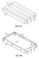
- FIG. 3A and 3B In this embodiment two heat pipes of rectangular cross section are embedded into slots 18 in the lid 17.
- the slots may be .27" wide and .14" inches deep.
- the figure shows two slots 18, but anywhere from, say, one to five (or even more) slots may be useful.
- the heat pipes might be .21" by .08" by 5" in size, and may be soldered or epoxied in place.
- Suitable materials for the lid 17 include aluminum, aluminum silicon, aluminum silicon carbide, copper, and copper tungsten.
- the outer containment vessel of the heat pipes may be of copper.
- Wicking structures for the heat pipes include fibers, sintered copper or a mesh of copper.
- the heat pipes may be charged with deionized water under a partial vacuum.
- a variety of other materials for the wick and working fluid e.g., ammonia, acetone, methanol are known, and are practical for this application.
- Figure 3B shows the underside of the lid 17. Notice the recessed surface 20, surrounded by a raised periphery 21. The amount of recess may be, say, .40". The raised periphery 21 makes contact with the substrate.
- This embodiment dispenses with individual component heat pipes in favor of the lid 22 itself and a cover plate 23 cooperating to create the outer containment vessel for one or more heat pipes.
- the lid 22 has one or more slots 24 covered by a cover plate 23.
- the slots 24 receive respective hollow wicking structures 25.
- the outer surface of hollow wicking structures 25 have a shape that allows them to fit snugly into the slots 24 and their cover plate 23, so as to be in mechanical and thermal contact therewith.
- the cover plate 23 is then hermetically affixed.
- Each heat pipe can then be evacuated and charged with a working fluid through a small hole such as hole 36 located in the cover 23 or a small hole 37 located in the end of the lid 22.
- the holes would, of course, be sealed after those operations.
- the result is a lid assembly (22/23) that is also intrinsically a heat pipe. Surface 28 on the lid 23 receives the heat sink (not shown).
- Figure 4B shows the underside of the lid 22 and cover plate 23. Note the raised periphery 26 surrounding a recessed surface 27. These correspond to their counterparts described in connection with Figure 3B.
- Suitable materials for the construction of the lid/heat pipe of Figures 4A and 4B include all those mentioned in connection with the embodiment of Figures 3A and 3B.
- a lid 29 has a number of bore holes 30, 31 and 32 therein, which may be 4 mm in diameter.
- the lid 29 itself may be on the order of one quarter of an inch in height.
- this embodiment (Fig. 5) can be like either the one of Figures 3A-B or the one of Figures 4A-B. That is, (as in the case of Fig. 3) one could take pre-existing separate heat pipes (either completed, or in kit form, as it were) and locate them in the bores 30, 31 and 32.
- Bore 30 is depicted as not passing all the way through the lid 29, whereas bores 31 and 32 are. Which style to use is, for a Fig. 3 style embodiment, a matter of choice.
- Methods for securing the heat pipes into the bores include adhesives, soldering and swaging or expanding them into place. Some of these, such as the swaging or expanding, may be more conveniently performed if the heat pipes are not fully assembled before their outer tubes (containment vessels) are affixed in the bores. If they are to be epoxied into place, then they might more conveniently be already completely functional finished heat pipes.
Landscapes
- Engineering & Computer Science (AREA)
- Life Sciences & Earth Sciences (AREA)
- Sustainable Development (AREA)
- Physics & Mathematics (AREA)
- Thermal Sciences (AREA)
- Mechanical Engineering (AREA)
- General Engineering & Computer Science (AREA)
- Cooling Or The Like Of Semiconductors Or Solid State Devices (AREA)
Applications Claiming Priority (3)
| Application Number | Priority Date | Filing Date | Title |
|---|---|---|---|
| US08/866,898 US6133631A (en) | 1997-05-30 | 1997-05-30 | Semiconductor package lid with internal heat pipe |
| US866898 | 1997-05-30 | ||
| EP98100847A EP0881675A3 (de) | 1997-05-30 | 1998-01-19 | Halbleiterpackung mit innerem Wärmerohr |
Related Parent Applications (1)
| Application Number | Title | Priority Date | Filing Date |
|---|---|---|---|
| EP98100847A Division EP0881675A3 (de) | 1997-05-30 | 1998-01-19 | Halbleiterpackung mit innerem Wärmerohr |
Publications (2)
| Publication Number | Publication Date |
|---|---|
| EP1381082A2 true EP1381082A2 (de) | 2004-01-14 |
| EP1381082A3 EP1381082A3 (de) | 2004-01-28 |
Family
ID=25348676
Family Applications (2)
| Application Number | Title | Priority Date | Filing Date |
|---|---|---|---|
| EP03023553A Withdrawn EP1381082A3 (de) | 1997-05-30 | 1998-01-19 | Halbleiterpackung mit innerem Wärmerohr |
| EP98100847A Withdrawn EP0881675A3 (de) | 1997-05-30 | 1998-01-19 | Halbleiterpackung mit innerem Wärmerohr |
Family Applications After (1)
| Application Number | Title | Priority Date | Filing Date |
|---|---|---|---|
| EP98100847A Withdrawn EP0881675A3 (de) | 1997-05-30 | 1998-01-19 | Halbleiterpackung mit innerem Wärmerohr |
Country Status (3)
| Country | Link |
|---|---|
| US (1) | US6133631A (de) |
| EP (2) | EP1381082A3 (de) |
| JP (1) | JP3445936B2 (de) |
Families Citing this family (56)
| Publication number | Priority date | Publication date | Assignee | Title |
|---|---|---|---|---|
| DE19860415A1 (de) * | 1998-12-28 | 2000-06-29 | Abb Research Ltd | Halbleitermodul |
| FI991510L (fi) * | 1999-07-01 | 2001-01-02 | Nokia Networks Oy | Järjestely lämmönlähteen generoiman lämpöenergian muualle johtamiseksi |
| US6437981B1 (en) * | 2000-11-30 | 2002-08-20 | Harris Corporation | Thermally enhanced microcircuit package and method of forming same |
| JP3818084B2 (ja) * | 2000-12-22 | 2006-09-06 | 日立電線株式会社 | 冷却板とその製造方法及びスパッタリングターゲットとその製造方法 |
| US6639799B2 (en) | 2000-12-22 | 2003-10-28 | Intel Corporation | Integrated vapor chamber heat sink and spreader and an embedded direct heat pipe attachment |
| US6525420B2 (en) * | 2001-01-30 | 2003-02-25 | Thermal Corp. | Semiconductor package with lid heat spreader |
| SG152908A1 (en) * | 2001-08-28 | 2009-06-29 | Advanced Materials Tech | Advanced microelectronic heat dissipation package and method for its manufacture |
| US7134486B2 (en) | 2001-09-28 | 2006-11-14 | The Board Of Trustees Of The Leeland Stanford Junior University | Control of electrolysis gases in electroosmotic pump systems |
| US6942018B2 (en) | 2001-09-28 | 2005-09-13 | The Board Of Trustees Of The Leland Stanford Junior University | Electroosmotic microchannel cooling system |
| US6574963B1 (en) | 2001-11-16 | 2003-06-10 | Intel Corporation | Electrical energy-generating heat sink system and method of using same to recharge an energy storage device |
| US7411337B2 (en) * | 2001-11-16 | 2008-08-12 | Intel Corporation | Electrical energy-generating system and devices and methods related thereto |
| KR20040058095A (ko) * | 2001-12-13 | 2004-07-03 | 소니 가부시끼 가이샤 | 냉각 장치, 전자기기 장치 및 냉각 장치의 제조 방법 |
| US6606251B1 (en) | 2002-02-07 | 2003-08-12 | Cooligy Inc. | Power conditioning module |
| TW537436U (en) * | 2002-05-31 | 2003-06-11 | Quanta Comp Inc | Three-phase variable heat conducting structure |
| US6665187B1 (en) * | 2002-07-16 | 2003-12-16 | International Business Machines Corporation | Thermally enhanced lid for multichip modules |
| US6945957B2 (en) | 2002-12-30 | 2005-09-20 | Scimed Life Systems, Inc. | Valve treatment catheter and methods |
| US20050098300A1 (en) * | 2003-09-12 | 2005-05-12 | Kenya Kawabata | Heat sink with heat pipes and method for manufacturing the same |
| EP1517166B1 (de) * | 2003-09-15 | 2015-10-21 | Nuvotronics, LLC | Vorrichtungsgehäuse und Verfahren zu derer Prüfung und Herstellung |
| US6992892B2 (en) * | 2003-09-26 | 2006-01-31 | Tokyo Electron Limited | Method and apparatus for efficient temperature control using a contact volume |
| US7269005B2 (en) * | 2003-11-21 | 2007-09-11 | Intel Corporation | Pumped loop cooling with remote heat exchanger and display cooling |
| TWM255996U (en) * | 2003-12-26 | 2005-01-21 | Advanced Semiconductor Eng | Heat spreader with heat pipe for semiconductor package |
| CN1328567C (zh) * | 2004-02-27 | 2007-07-25 | 鸿富锦精密工业(深圳)有限公司 | 热管 |
| US20050219819A1 (en) * | 2004-03-31 | 2005-10-06 | Himanshu Pokharna | Methods to improve heat exchanger performance in liquid cooling loops |
| US7168152B1 (en) * | 2004-10-18 | 2007-01-30 | Lockheed Martin Corporation | Method for making an integrated active antenna element |
| DK1681527T3 (da) * | 2005-01-17 | 2007-09-10 | Cpumate Inc | Fremgangsmåde til fremstilling af et isotermisk pladeaggregat med forudbestemt form |
| JP4556759B2 (ja) * | 2005-04-28 | 2010-10-06 | 日立電線株式会社 | ヒートパイプ式熱交換器及びその製造方法 |
| US7215032B2 (en) | 2005-06-14 | 2007-05-08 | Cubic Wafer, Inc. | Triaxial through-chip connection |
| US7687400B2 (en) | 2005-06-14 | 2010-03-30 | John Trezza | Side stacking apparatus and method |
| US7884483B2 (en) | 2005-06-14 | 2011-02-08 | Cufer Asset Ltd. L.L.C. | Chip connector |
| US7851348B2 (en) | 2005-06-14 | 2010-12-14 | Abhay Misra | Routingless chip architecture |
| US7838997B2 (en) | 2005-06-14 | 2010-11-23 | John Trezza | Remote chip attachment |
| US7786592B2 (en) * | 2005-06-14 | 2010-08-31 | John Trezza | Chip capacitive coupling |
| US8456015B2 (en) | 2005-06-14 | 2013-06-04 | Cufer Asset Ltd. L.L.C. | Triaxial through-chip connection |
| US7560813B2 (en) * | 2005-06-14 | 2009-07-14 | John Trezza | Chip-based thermo-stack |
| US7781886B2 (en) | 2005-06-14 | 2010-08-24 | John Trezza | Electronic chip contact structure |
| DE102006007303A1 (de) * | 2006-02-16 | 2007-08-30 | Infineon Technologies Ag | Leiterplatte |
| JP2007273233A (ja) * | 2006-03-31 | 2007-10-18 | Fujitsu Ltd | ソケット、ソケットを有する回路部品及び回路部品を備える情報処理装置 |
| US7551440B2 (en) * | 2007-01-24 | 2009-06-23 | Hewlett-Packard Development Company, L.P. | System and method for cooling an electronic component |
| TW200849295A (en) * | 2007-06-15 | 2008-12-16 | Fu-Chia Chang | Super-conducting uniform-temperature heat dissipating module |
| CN101408301B (zh) * | 2007-10-10 | 2012-09-19 | 富准精密工业(深圳)有限公司 | 带有散热装置的发光二极管灯具 |
| US9746248B2 (en) | 2011-10-18 | 2017-08-29 | Thermal Corp. | Heat pipe having a wick with a hybrid profile |
| US8824145B2 (en) | 2012-06-08 | 2014-09-02 | Infineon Technologies Ag | Electric device package and method of making an electric device package |
| US11006548B2 (en) * | 2013-02-01 | 2021-05-11 | Smart Embedded Computing, Inc. | Method and device to provide uniform cooling in rugged environments |
| US9202772B2 (en) * | 2013-02-28 | 2015-12-01 | Altera Corporation | Heat pipe in overmolded flip chip package |
| DE202013002411U1 (de) * | 2013-03-12 | 2013-06-27 | Congatec Ag | Wärmeverteiler mit Flachrohrkühlelement |
| KR102546241B1 (ko) | 2016-10-05 | 2023-06-22 | 삼성전자주식회사 | 반도체 패키지 |
| KR102617349B1 (ko) * | 2016-12-02 | 2023-12-26 | 삼성전자주식회사 | 인쇄회로기판, 및 이를 가지는 솔리드 스테이트 드라이브 장치 |
| JP6905678B2 (ja) * | 2017-03-27 | 2021-07-21 | 大日本印刷株式会社 | ベーパーチャンバ、ベーパーチャンバ搭載基板およびベーパーチャンバ用金属シート |
| US10622282B2 (en) * | 2017-07-28 | 2020-04-14 | Qualcomm Incorporated | Systems and methods for cooling an electronic device |
| JP6984252B2 (ja) * | 2017-09-07 | 2021-12-17 | 株式会社村田製作所 | 半導体パッケージ |
| US10319654B1 (en) | 2017-12-01 | 2019-06-11 | Cubic Corporation | Integrated chip scale packages |
| CN110392512A (zh) * | 2018-04-16 | 2019-10-29 | 富泰华工业(深圳)有限公司 | 电子设备的主板散热系统 |
| CN109686708A (zh) * | 2018-12-24 | 2019-04-26 | 中国电子科技集团公司第五十八研究所 | 一种气密性及非气密性封装的散热结构 |
| US11754343B2 (en) * | 2019-11-05 | 2023-09-12 | Toyota Motor Engineering & Manufacturing North America, Inc. | Phase change heat-storing mechanisms for substrates of electronic assemblies |
| EP4424116A4 (de) * | 2021-10-28 | 2025-07-23 | Ericsson Telefon Ab L M | Trägersubstrat, verfahren und elektronische anordnung |
| CN120417227A (zh) * | 2025-05-25 | 2025-08-01 | 宁波安贝智能控制技术有限公司 | 一种防水线路板 |
Family Cites Families (11)
| Publication number | Priority date | Publication date | Assignee | Title |
|---|---|---|---|---|
| EP0251836B1 (de) * | 1986-05-30 | 1991-07-17 | Digital Equipment Corporation | Vollständiges Wärmerohr-Modul |
| JPH02110296A (ja) * | 1988-10-17 | 1990-04-23 | Nippon Alum Mfg Co Ltd | 平板状ヒートパイプ |
| US4880052A (en) * | 1989-02-27 | 1989-11-14 | Thermacore, Inc. | Heat pipe cooling plate |
| JPH04146657A (ja) * | 1990-10-08 | 1992-05-20 | Matsushita Electric Ind Co Ltd | 半導体集積回路の放熱装置 |
| JPH04184963A (ja) * | 1990-11-20 | 1992-07-01 | Toshiba Corp | ヒートシンク |
| JPH04356000A (ja) * | 1991-01-31 | 1992-12-09 | Furukawa Electric Co Ltd:The | 基板に取り付けた発熱部品の冷却構造 |
| IT1252762B (it) * | 1991-07-04 | 1995-06-28 | Lando Baldassini | Variatore di velocita' rotatoria e lineare per motori a due tempi applicabile all'albero motore. |
| US5355942A (en) * | 1991-08-26 | 1994-10-18 | Sun Microsystems, Inc. | Cooling multi-chip modules using embedded heat pipes |
| US5323292A (en) * | 1992-10-06 | 1994-06-21 | Hewlett-Packard Company | Integrated multi-chip module having a conformal chip/heat exchanger interface |
| GB2278676B (en) * | 1993-05-14 | 1997-05-07 | Furukawa Electric Co Ltd | Heat pipe type radiator and method for manufacturing same |
| US5880524A (en) * | 1997-05-05 | 1999-03-09 | Intel Corporation | Heat pipe lid for electronic packages |
-
1997
- 1997-05-30 US US08/866,898 patent/US6133631A/en not_active Expired - Lifetime
-
1998
- 1998-01-19 EP EP03023553A patent/EP1381082A3/de not_active Withdrawn
- 1998-01-19 EP EP98100847A patent/EP0881675A3/de not_active Withdrawn
- 1998-05-28 JP JP16418498A patent/JP3445936B2/ja not_active Expired - Fee Related
Also Published As
| Publication number | Publication date |
|---|---|
| EP0881675A2 (de) | 1998-12-02 |
| US6133631A (en) | 2000-10-17 |
| EP0881675A3 (de) | 1999-12-08 |
| EP1381082A3 (de) | 2004-01-28 |
| JPH11233698A (ja) | 1999-08-27 |
| JP3445936B2 (ja) | 2003-09-16 |
Similar Documents
| Publication | Publication Date | Title |
|---|---|---|
| US6133631A (en) | Semiconductor package lid with internal heat pipe | |
| US5367193A (en) | Low cost, thermally efficient, and surface mountable semiconductor package for a high applied power VLSI die | |
| US6373703B2 (en) | Integral design features for heatsink attach for electronic packages | |
| EP0529837B1 (de) | Verfahren und Apparat zum Kühlen von Mehrchip-Moduln durch die vollständige Wärmerohr-Technologie | |
| US5819402A (en) | Method for cooling of chips using blind holes with customized depth | |
| US5513070A (en) | Dissipation of heat through keyboard using a heat pipe | |
| US5920458A (en) | Enhanced cooling of a heat dissipating circuit element | |
| US5880524A (en) | Heat pipe lid for electronic packages | |
| EP1493186B1 (de) | Wärmeverteiler mit befestigungsfuss | |
| US4327399A (en) | Heat pipe cooling arrangement for integrated circuit chips | |
| US7511372B2 (en) | Microelectronic die cooling device including bonding posts and method of forming same | |
| US5604978A (en) | Method for cooling of chips using a plurality of materials | |
| US20020056908A1 (en) | Heatpipesink having integrated heat pipe and heat sink | |
| KR102429675B1 (ko) | 모놀리식 마이크로파 통합 회로(mmic) 냉각 구조 | |
| US6365260B1 (en) | Arrangement for heat dissipation in chip modules on multilayered ceramic carriers, in particular multichip modules | |
| EP0714127A2 (de) | Halbleitergehäuse | |
| JPH0786471A (ja) | 半導体モジュ−ル | |
| US10141240B2 (en) | Semiconductor device, corresponding circuit and method | |
| US7176382B1 (en) | Electrical circuit board and method for making the same | |
| US7679911B2 (en) | Electronic package whereby an electronic assembly is packaged within an enclosure that is designed to act as a heat pipe | |
| JP2003115569A (ja) | 放熱装置組付方法及びアセンブリ基板 | |
| EP0709884A2 (de) | Mikroelektronische Anordnung bestehend aus einer Packung mit internen Leitungen zur Führung einer Kühlflüssigkeit | |
| US12315781B2 (en) | Heat spreader for a semiconductor package | |
| US6266251B1 (en) | Cavity-down ball grid array module | |
| US20070190685A1 (en) | Cooling facility and method for integrated circuit |
Legal Events
| Date | Code | Title | Description |
|---|---|---|---|
| PUAI | Public reference made under article 153(3) epc to a published international application that has entered the european phase |
Free format text: ORIGINAL CODE: 0009012 |
|
| PUAL | Search report despatched |
Free format text: ORIGINAL CODE: 0009013 |
|
| 17P | Request for examination filed |
Effective date: 20031015 |
|
| AC | Divisional application: reference to earlier application |
Ref document number: 0881675 Country of ref document: EP Kind code of ref document: P |
|
| AK | Designated contracting states |
Kind code of ref document: A2 Designated state(s): DE FR GB |
|
| AK | Designated contracting states |
Kind code of ref document: A3 Designated state(s): DE FR GB |
|
| 17Q | First examination report despatched |
Effective date: 20040308 |
|
| AKX | Designation fees paid |
Designated state(s): DE FR GB |
|
| STAA | Information on the status of an ep patent application or granted ep patent |
Free format text: STATUS: THE APPLICATION IS DEEMED TO BE WITHDRAWN |
|
| 18D | Application deemed to be withdrawn |
Effective date: 20110802 |