EP1380520A2 - Dispositif de distribution destiné à équiper un récipient muni d'une valve - Google Patents
Dispositif de distribution destiné à équiper un récipient muni d'une valve Download PDFInfo
- Publication number
- EP1380520A2 EP1380520A2 EP03291200A EP03291200A EP1380520A2 EP 1380520 A2 EP1380520 A2 EP 1380520A2 EP 03291200 A EP03291200 A EP 03291200A EP 03291200 A EP03291200 A EP 03291200A EP 1380520 A2 EP1380520 A2 EP 1380520A2
- Authority
- EP
- European Patent Office
- Prior art keywords
- dispensing
- cover
- valve
- button
- push
- Prior art date
- Legal status (The legal status is an assumption and is not a legal conclusion. Google has not performed a legal analysis and makes no representation as to the accuracy of the status listed.)
- Granted
Links
Images


Classifications
-
- B—PERFORMING OPERATIONS; TRANSPORTING
- B65—CONVEYING; PACKING; STORING; HANDLING THIN OR FILAMENTARY MATERIAL
- B65D—CONTAINERS FOR STORAGE OR TRANSPORT OF ARTICLES OR MATERIALS, e.g. BAGS, BARRELS, BOTTLES, BOXES, CANS, CARTONS, CRATES, DRUMS, JARS, TANKS, HOPPERS, FORWARDING CONTAINERS; ACCESSORIES, CLOSURES, OR FITTINGS THEREFOR; PACKAGING ELEMENTS; PACKAGES
- B65D83/00—Containers or packages with special means for dispensing contents
- B65D83/14—Containers for dispensing liquid or semi-liquid contents by internal gaseous pressure, i.e. aerosol containers comprising propellant
- B65D83/16—Actuating means
- B65D83/20—Actuator caps
-
- B—PERFORMING OPERATIONS; TRANSPORTING
- B05—SPRAYING OR ATOMISING IN GENERAL; APPLYING FLUENT MATERIALS TO SURFACES, IN GENERAL
- B05B—SPRAYING APPARATUS; ATOMISING APPARATUS; NOZZLES
- B05B11/00—Single-unit hand-held apparatus in which flow of contents is produced by the muscular force of the operator at the moment of use
- B05B11/01—Single-unit hand-held apparatus in which flow of contents is produced by the muscular force of the operator at the moment of use characterised by the means producing the flow
- B05B11/10—Pump arrangements for transferring the contents from the container to a pump chamber by a sucking effect and forcing the contents out through the dispensing nozzle
- B05B11/1001—Piston pumps
- B05B11/1015—Piston pumps actuated without substantial movement of the nozzle in the direction of the pressure stroke
Definitions
- the present invention relates to dispensing devices.
- Such a device is known from FR-A-2 814 726 but cannot operate with a valve allowing the valve stem to be pushed in over a long stroke before to initiate the distribution of the product.
- the device described in FR 1,572,537 uses a metal spring to act on the dispensing nozzle, which is relatively expensive.
- the invention aims in particular to allow the use of a distribution device of the type mentioned above in combination with a valve requiring only a small amount displacement of the valve stem to cause the distribution of the product.
- the invention relates to a device in which the push button is configured to, when pressed to dispense product, move in a first phase, the dispensing orifice relative to the cover, so that it comes opposite the opening of the hood, the conduit of the dispensing nozzle being able to deform to allow movement of the dispensing orifice without actuation of the distribution element during the first phase, then in a second phase cause the dispensing element to be actuated.
- the invention makes it possible to produce a device for relatively low cost. reliable distribution capable of being used in combination with a distribution element such as a valve or a pump requiring only a small displacement of a rod of order to cause the distribution of the product.
- This intermediate part may include flexible material bridges, and the duct can advantageously be carried out at least partially inside one of said bridges.
- At least one of the bridges may have a cross section substantially rectangular, long side substantially perpendicular to a direction of travel distributor nozzle for actuating the distribution element, this direction may coincide for example with a longitudinal axis of a valve stem.
- the intermediate part may include, for example, three bridges arranged approximately 120 ° from each other.
- the push button can be configured to train on the move, during the first phase above, the peripheral part without driving the central part, then during the second phase also train the central part.
- the force exerted by the intermediate part on the central part when the push button starts to be released while the dispensing element is in dispensing position, may be less than the force exerted by the dispensing element on the central part to return to its initial state.
- the central part, the intermediate part and the peripheral part can be made in one piece by molding material, in the same material or in several materials, with for example a thermoplastic elastomer for the bridges of material connecting the central and peripheral parts.
- the peripheral part may include at least one stiffening rib oriented obliquely inward, on the side of the push button.
- the latter can have a skirt configured to press by its free edge on a support surface located radially outside this rib.
- the central part may include a protruding element on the side of the push button and the latter may include an inner skirt in which can engage this protruding element, the inner skirt being configured to press by its free edge on a bearing surface of the central part, surrounding the projecting element.
- the dispensing orifice can be defined for example by a channel nozzle eddy.
- the dispensing nozzle may have a wall capable of being positioned opposite of the hood opening when the push button is at rest.
- the dispensing element may include a control rod, such a rod being also called valve stem when the dispensing element is a valve.
- the invention also relates to a container equipped with a distribution device as defined above.
- This container may include a valve comprising a valve stem by which the product is dispensed when the valve is actuated.
- the axial displacement of the valve stem required to actuate the valve can be less than or equal to 2 mm, by example.
- the drawing shows a distribution device 1 intended to equip a container 2, the latter being partially shown in FIGS. 3 and 4.
- the container 2 comprises for example a pressurized container 3 provided with a valve 90 set in a cup closing the upper part of the container 3, so conventional, this valve 90 having a valve stem 4, hollow.
- the valve can be of any known type, the actuation being effected by example by pushing the rod 4 with a stroke less than or equal to 2 mm.
- the container 2 can contain a product to be sprayed, for example a product cosmetic, and a propellant, which may or may not be stored in a liquefied form in container 2 and whether or not be delivered with the product.
- a product to be sprayed for example a product cosmetic
- a propellant which may or may not be stored in a liquefied form in container 2 and whether or not be delivered with the product.
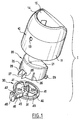
- the dispensing device 1 comprises a cover 10, a push button 20 and a dispenser nozzle 30.
- the cover 10 includes a mounting skirt 11 provided in the lower part with a bead 12 allowing it to be fixed by snap-fastening in an annular groove 5 present at the upper part of the container 3.
- the mounting skirt 11 is crossed by an opening 13, through which can be carried out the distribution of the product, when the push button 20 is as depicted in Figure 4.
- the opening 13 is for example, as illustrated, of generally circular shape.
- the mounting skirt 11 is connected at the top to an interior skirt 14, the latter defining an opening 15 allowing access to the push button 20.
- the latter has an upper wall 21, intended to serve as a support for a finger the user, connecting at the periphery to a first skirt 22 extending at least partially opposite the inner skirt 14 of the cover 10.
- the push button 20 has inside the first skirt 22 a second skirt 23, cylindrical of revolution and substantially of the same axis X as the rod valve 4.
- the first skirt 22 is provided externally with vertical ribs 26, as can be seen in figure 1, as well as in the lower part of a lateral opening 27 bordered by two vertical tabs 28 intended to come to bear on the dispensing nozzle 30.
- the push button 20 also includes a horizontal tab 29 intended to prevent it from leaving the cover 10, coming into abutment against the latter.
- the dispensing nozzle 30 comprises a central part 31 comprising at lower part a cylindrical skirt 32 defining a shouldered housing in which can engaging the upper part of the valve stem 4 in a substantially sealed manner, as can be seen in Figure 4.
- a shouldered housing in which can engaging the upper part of the valve stem 4 in a substantially sealed manner, as can be seen in Figure 4.
- the rod valve 4 abuts by its upper end 4a against the shoulder of the housing.
- the central part 31 is provided in the upper part with a projecting element 33, in general point shape, formed by three walls 33a arranged at 120 ° from each other other.
- the central part 31 defines, around the projecting element 33 and at its base, a bearing surface 34 against which can come press the second skirt 23 of the push button by its lower end 23a, when the push button 20 is pressed enough.
- the dispensing nozzle 30 comprises, in addition to the central part 31, a part peripheral 40 of generally annular shape.
- the central 31 and peripheral 40 parts are interconnected by bridges of material forming a spring, namely in the example illustrated two substantially radial arms 41 arranged at 120 ° from one another and a substantially radial duct 42 disposed at 120 ° with each of the arms 41.
- Each arm 41 has a generally rectangular cross section flattened, long side perpendicular to the X axis.
- the duct 42 has a cross section of generally circular shape.
- the peripheral part 40 has an annular rib 43, extending obliquely inward on the side of the push button 20, being interrupted at the connection of the arms 41 and at an opening 45 extending around the duct 42.
- the peripheral part 40 includes a nozzle support 46 to which the conduit 42 is connected and on which a nozzle with vortex channels 50 can be fixed, conventional, as can be seen in Figures 3 and 4.
- the support 46 present in this indeed a pad 47 also called "centerpost".
- the support 46 comprises, in the lower part, a wall 48 which is positioned behind the opening 13 when the push button 20 is at rest, as can be seen in Figure 3, in order to close it.
- the nozzle 50 defines a dispensing orifice 51.
- the dispensing nozzle 30 is made in one piece by molding of plastic material (s).
- the material in which the tip is made distributor 30 is chosen in such a way that the peripheral part 40 can move axially with respect to the central part 31 by elastic deformation of the arms 41 and of the conduit 42.
- the peripheral part 40 defines, radially outside the rib 43, a bearing surface 49 on which the first skirt 22 of the push button can rest 20 by its lower end 22a, as can be seen in FIG. 2.
- the operation of the dispensing device 1 is as follows.
- the wall 48 is located behind the opening 13 and prevents impurities from entering inside the cover 10.
- the dispensing orifice 51 is protected by the wall of the cover 11 which is located above this opening 13.
- the push button 20 drives the moving part device 40 downwards, which has the effect of positioning the dispensing orifice 51 in look of the opening 13.
- the rod of valve 4 is not substantially or insufficiently displaced for the valve to be actuated, the force to be exerted on the valve stem 4 to actuate the valve being greater than the force necessary to move the peripheral part 40 relative to the central part 31 in order to bring the dispensing orifice 51 opposite the opening 13.
- the continuation of the descent movement of the push button 20 is accompanied by a depression of the valve stem 4 of a sufficient stroke to actuate the valve.
- the dispensing orifice 51 is located at this time at near the center of the opening 13 and the product contained in the container 2 can leave the inner channel of the valve stem 4, circulate inside the central part 31 and gain the conduit 42 then the nozzle 50.
- the force exerted by the arms 41 and the conduit 42 on the central part 31, when the push button 20 begins to be released while the valve is being distribution, is less than the force exerted by the valve stem 4 on the central part 31 when it returns to its initial state.
- valve stem 4 can rise and the distribution of the product is interrupted, the skirt 22 being also still pressing on the peripheral part 40.
- the dispensing element can for example be constituted by a valve devoid of valve stem.
- FIG. 5 shows a device 1 ′ which differs from that previously described with reference to Figures 1 to 4 by the fact that the valve 90 'used is of the type without valve stem, the central part 31 being replaced by a central part 31 'configured to support a valve control member, not visible on the figure, in order to cause the distribution of the product.
- the invention also applies to the case where the distribution element is a pump.
- FIG. 6 a variant comprising a pump 100 having a control rod 101 similar to the valve rod 4 previously described.
- the push button and the cover can for example be produced under the form of a single piece produced by molding, the push button being for example connected by a hinge 80 on the cover, as illustrated in FIG. 7.
Landscapes
- Chemical & Material Sciences (AREA)
- Dispersion Chemistry (AREA)
- Engineering & Computer Science (AREA)
- Mechanical Engineering (AREA)
- Containers And Packaging Bodies Having A Special Means To Remove Contents (AREA)
- Closures For Containers (AREA)
- Nozzles (AREA)
Abstract
- un capot (10),
- un embout distributeur (30), comportant :
- un orifice de distribution (51), et
- un conduit (42) pour canaliser le produit sortant de l'élément de distribution vers l'orifice de distribution,
- un bouton-poussoir (20) mobile par rapport au capot. Le bouton-poussoir
(20) est configuré pour, lorsqu'actionné pour distribuer du produit :
- déplacer dans une première phase l'orifice de distribution (51) par rapport au capot, de manière à ce qu'il vienne en regard de l'ouverture (13) du capot, le conduit (42) de l'embout distributeur (30) étant apte à se déformer pour permettre le déplacement de l'orifice de distribution (51) sans actionnement de l'élément de distribution durant cette première phase,
- puis dans une deuxième phase actionner l'élément de distribution.
Description
- un capot, encore appelé parfois « frette », destiné à être fixé sur le récipient, ce capot présentant une ouverture,
- un embout distributeur mobile par rapport au capot, cet embout distributeur
comportant :
- un orifice de distribution, et
- un conduit pour canaliser le produit sortant de l'élément de distribution vers l'orifice de distribution,
- un bouton-poussoir mobile par rapport au capot pour agir sur l'embout distributeur afin d'actionner l'élément de distribution, le capot étant configuré d'une part pour masquer l'orifice de distribution quand le bouton-poussoir est au repos et d'autre part pour permettre à l'orifice de distribution de se positionner en regard de l'ouverture du capot quand le bouton-poussoir est enfoncé pour provoquer l'actionnement de l'élément de distribution, c'est-à-dire la distribution du produit.
- une partie périphérique, par rapport à laquelle l'orifice de distribution est fixe,
- une partie centrale coopérant avec l'élément de distribution, et
- une partie intermédiaire élastiquement déformable, reliant les parties centrale et périphérique.
- la figure 1 est une vue schématique en perspective éclatée d'un dispositif de distribution réalisé conformément à l'invention,
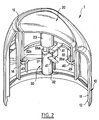
- la figure 2 est une vue schématique en perspective, avec arrachement, du dispositif de la figure 1, à l'état assemblé,
- la figure 3 représente en coupe axiale schématique le dispositif de la figure 1 en place sur un récipient, le bouton-poussoir n'étant pas enfoncé,
- la figure 4 est une vue analogue à la figure 3, représentant le dispositif en cours de distribution,
- la figure 5 est une vue analogue à la figure 3, représentant une variante de réalisation dans laquelle l'élément de distribution est une valve sans tige de valve,
- la figure 6 représente une autre variante dans laquelle l'élément de distribution est une pompe, et
- la figure 7 est une vue partielle et schématique illustrant la réalisation du capot et du bouton-poussoir d'une seule pièce par moulage.
Claims (21)
- Dispositif de distribution (1) destiné à équiper un récipient (2) muni d'un élément de distribution (90 ; 90' ; 100) par lequel du produit contenu dans le récipient peut sortir quand cet élément est actionné, ce dispositif comportant :un capot (10) présentant une ouverture (13),un embout distributeur (30), mobile par rapport au capot et comportant :un orifice de distribution (51), etun conduit (42) pour canaliser le produit sortant de l'élément de distribution vers l'orifice de distribution,un bouton-poussoir (20) mobile par rapport au capot, pour agir sur l'embout distributeur (30) afin d'actionner l'élément de distribution (90 ; 90' ; 100), le capot (10) étant configuré pour masquer l'orifice de distribution (51) quand le bouton-poussoir est au repos et permettre à l'orifice de distribution (51) de se positionner en regard de l'ouverture (13) du capot quand le bouton-poussoir est enfoncé pour provoquer l'actionnement de l'élément de distribution, le bouton-poussoir (20) étant configuré pour, lorsqu'actionné pour distribuer du produit :déplacer dans une première phase l'orifice de distribution (51) par rapport au capot, de manière à ce qu'il vienne en regard de l'ouverture (13) du capot, le conduit (42) de l'embout distributeur (30) étant apte à se déformer pour permettre le déplacement de l'orifice de distribution (51) sans actionnement de l'élément de distribution (90 ; 90' ; 100) durant cette première phase,puis dans une deuxième phase actionner l'élément de distribution.
- Dispositif selon la revendication 1, caractérisé par le fait que l'embout distributeur (30) comporte :une partie périphérique (40), par rapport à laquelle l'orifice de distribution (51) est fixe,une partie centrale (31) coopérant avec l'élément de distribution, etune partie intermédiaire (41, 42) élastiquement déformable, reliant les parties centrale et périphérique.
- Dispositif selon la revendication 2, caractérisé par le fait que la partie intermédiaire comporte des ponts de matière (41, 42) flexibles.
- Dispositif selon la revendication 3, caractérisé par le fait que le conduit (42) est réalisé au moins partiellement à l'intérieur de l'un desdits ponts.
- Dispositif selon la revendication 3 ou 4, caractérisé par le fait que l'un au moins des ponts (41) présente une section droite sensiblement rectangulaire, de grand côté sensiblement perpendiculaire à une direction de déplacement de l'embout distributeur pour l'actionnement de l'élément de distribution.
- Dispositif selon l'une quelconque des trois revendications immédiatement précédentes, caractérisé par le fait que la partie intermédiaire comporte trois ponts (41, 42) disposés sensiblement à 120° les uns des autres.
- Dispositif selon l'une quelconque des revendications 2 à 5, caractérisé par le fait que le bouton-poussoir (20) est configuré pour entraíner en déplacement, durant la première phase, la partie périphérique (40) sans entraíner la partie centrale (31), puis durant la deuxième phase entraíner la partie centrale.
- Dispositif selon l'une quelconque des revendications 2 à 7, caractérisé par le fait que la force exercée par la partie intermédiaire sur la partie centrale (31), lorsque le bouton-poussoir commence à être relâché alors que l'élément de distribution est en position de distribution, est inférieure à la force exercée par l'élément de distribution sur la partie centrale pour revenir dans son état initial.
- Dispositif selon l'une quelconque des revendications 2 à 8, caractérisé par le fait que la partie centrale (31), la partie intermédiaire (41, 42) et la partie périphérique (40) sont réalisées d'une seule pièce par moulage de matière.
- Dispositif selon l'une quelconque des revendications 2 à 9, caractérisé par le fait que la partie périphérique (40) comporte au moins une nervure de rigidification (43) orientée obliquement vers l'intérieur, du côté du bouton-poussoir, et par le fait que le bouton-poussoir (20) comporte une jupe (22) configurée pour appuyer par son bord libre (22a) sur une surface d'appui (49) située radialement à l'extérieur de la nervure (43).
- Dispositif selon l'une quelconque des revendications 2 à 10, caractérisé par le fait que la partie centrale (31) comporte un élément en saillie (33) du côté du bouton-poussoir et par le fait que ce dernier comporte une jupe (23) dans laquelle peut s'engager l'élément en saillie, la jupe (23) étant configurée pour appuyer par son bord libre (23a) sur une surface d'appui (34) de la partie centrale, entourant l'élément en saillie.
- Dispositif selon l'une quelconque des revendications précédentes, caractérisé par le fait que l'orifice de distribution (51) est défini par une buse (50) à canaux tourbillonnaires.
- Dispositif selon l'une quelconque des revendications précédentes, caractérisé par le fait que l'embout distributeur (30) comporte une paroi (48) apte à se positionner en regard de l'ouverture du capot lorsque le bouton-poussoir est au repos.
- Dispositif selon l'une quelconque des revendications précédentes, caractérisé par le fait que l'élément de distribution comporte une tige de commande (4 ; 101).
- Dispositif selon l'une quelconque des revendications précédentes, caractérisé par le fait que l'élément de distribution est une valve (90 ; 90').
- Dispositif selon l'une quelconque des revendications 1 à 14, caractérisé par le fait que l'élément de distribution est une pompe (100).
- Dispositif selon l'une quelconque des revendications précédentes, caractérisé par le fait que le capot et le bouton-poussoir sont réalisés d'une seule pièce par moulage de matière.
- Dispositif selon la revendication 17, caractérisé par le fait que le capot et le bouton-poussoir sont reliés par une charnière (80).
- Récipient équipé d'un dispositif de distribution (1) tel que défini dans l'une quelconque des revendications précédentes.
- Récipient selon la revendication 19, caractérisé par le fait qu'il comporte une valve comportant une tige de valve (4) par laquelle le produit est distribué lorsque la valve est actionnée.
- Récipient selon la revendication 20, caractérisé par le fait que la valve est actionnée par un déplacement axial de la tige de valve (4) inférieur ou égal à 2 mm.
Applications Claiming Priority (2)
| Application Number | Priority Date | Filing Date | Title |
|---|---|---|---|
| FR0206362A FR2839952B1 (fr) | 2002-05-24 | 2002-05-24 | Dispositif de distribution destine a equiper un recipient muni d'une valve |
| FR0206362 | 2002-05-24 |
Publications (3)
| Publication Number | Publication Date |
|---|---|
| EP1380520A2 true EP1380520A2 (fr) | 2004-01-14 |
| EP1380520A3 EP1380520A3 (fr) | 2004-11-10 |
| EP1380520B1 EP1380520B1 (fr) | 2005-10-12 |
Family
ID=29415056
Family Applications (1)
| Application Number | Title | Priority Date | Filing Date |
|---|---|---|---|
| EP03291200A Expired - Lifetime EP1380520B1 (fr) | 2002-05-24 | 2003-05-21 | Dispositif de distribution destiné à équiper un récipient muni d'une valve |
Country Status (5)
| Country | Link |
|---|---|
| US (1) | US7036691B2 (fr) |
| EP (1) | EP1380520B1 (fr) |
| DE (1) | DE60301829T2 (fr) |
| ES (1) | ES2247500T3 (fr) |
| FR (1) | FR2839952B1 (fr) |
Cited By (5)
| Publication number | Priority date | Publication date | Assignee | Title |
|---|---|---|---|---|
| JP2007525316A (ja) * | 2003-12-17 | 2007-09-06 | プレシジョン、ヴァルヴ、コーパレイシャン | エーロゾル弁アクチュエータ |
| WO2016110641A1 (fr) | 2015-01-09 | 2016-07-14 | L'oreal | Tête de distribution à buse non éjectable |
| JP2021511262A (ja) * | 2018-01-23 | 2021-05-06 | ザ プロクター アンド ギャンブル カンパニーThe Procter & Gamble Company | 発泡性製品に好適な分注装置 |
| US11208254B2 (en) | 2018-11-08 | 2021-12-28 | The Procter And Gamble Company | Dip tube aerosol dispenser with upright actuator |
| US11267644B2 (en) | 2018-11-08 | 2022-03-08 | The Procter And Gamble Company | Aerosol foam dispenser and methods for delivering a textured foam product |
Families Citing this family (50)
| Publication number | Priority date | Publication date | Assignee | Title |
|---|---|---|---|---|
| EP1599409B1 (fr) * | 2003-03-03 | 2009-10-21 | Seaquist Perfect Dispensing Foreign, Inc. | Actionneur d'aerosol |
| US20070290007A1 (en) * | 2004-11-30 | 2007-12-20 | The Procter & Gamble Company | Cap with an angled spray channel for an aerosol container or a spray container |
| FR2881721A1 (fr) * | 2005-02-09 | 2006-08-11 | Innovation Packaging Sarl | Bouton poussoir |
| FR2886631B1 (fr) * | 2005-06-03 | 2010-10-29 | Valois Sas | Tete de distribution de produit fluide et dispositif incorporant une telle tete |
| JP2009502674A (ja) * | 2005-07-29 | 2009-01-29 | シュ パッケージング プロダクツ リミテッド | 弁を備える液体および発射気体用の容器 |
| FR2900645B1 (fr) * | 2006-05-04 | 2008-07-11 | Valois Sas | Tete de distribution de produit fluide distributeur comprenant une telle tete et procede de fabrication d'une telle tete |
| US7721920B2 (en) * | 2006-05-31 | 2010-05-25 | The Clorox Company | Ergonomic cap for plastic aerosol container |
| AU2013203223B2 (en) * | 2007-01-04 | 2015-04-16 | Precision Valve Corporation | Locking Aerosol Dispenser |
| US7699190B2 (en) * | 2007-01-04 | 2010-04-20 | Precision Valve Corporation | Locking aerosol dispenser |
| WO2011003752A1 (fr) * | 2009-07-10 | 2011-01-13 | Unilever Plc | Ensemble capuchon pulvérisateur pour un récipient de fluide sous pression |
| FR2950272B1 (fr) | 2009-09-23 | 2012-06-01 | Oreal | Distributeur de produit cosmetique sur une surface de reception, dispositif de distribution et procede associe. |
| USD627224S1 (en) | 2009-10-08 | 2010-11-16 | S.C. Johnson & Son, Inc. | Overcap |
| US9211994B2 (en) | 2010-05-21 | 2015-12-15 | S.C. Johnson & Son, Inc. | Shroud and dispensing system for a handheld container |
| US20120000940A1 (en) | 2010-05-21 | 2012-01-05 | Andersen Daniel A | Shroud and dispensing system for a handheld countainer |
| US8936180B2 (en) * | 2010-08-23 | 2015-01-20 | Meadwestvaco Calmar, Inc. | Aerosol trigger sprayer and methods for making the same |
| USD652319S1 (en) | 2010-11-18 | 2012-01-17 | S.C. Johnson & Son, Inc. | Container |
| US8960504B2 (en) * | 2011-01-21 | 2015-02-24 | The Gillette Company | Actuator for a dispensing apparatus |
| USD666491S1 (en) | 2011-07-15 | 2012-09-04 | S.C. Johnson & Son, Inc. | Overcap |
| US9981799B2 (en) | 2011-08-09 | 2018-05-29 | S.C. Johnson & Son, Inc. | Dispensing system |
| US8967436B2 (en) | 2011-08-09 | 2015-03-03 | S.C. Johnson & Son, Inc. | Dispensing system |
| DE102012200545A1 (de) * | 2012-01-16 | 2013-07-18 | Aptar Radolfzell Gmbh | Medienspender |
| CN103420022B (zh) * | 2012-05-16 | 2015-09-09 | 丁要武 | 按压式液体泵 |
| DE102012016605A1 (de) * | 2012-07-06 | 2014-01-09 | Aptar Dortmund Gmbh | Abgabekopf und Abgabevorrichtung |
| US9260237B2 (en) | 2012-12-18 | 2016-02-16 | Precision Valve Corporation | Cap for dispensing liquids or gels |
| BR302013001271S1 (pt) * | 2013-03-26 | 2014-06-10 | Natura Cosmeticos Sa | Configuração aplicada em frasco dispensador |
| ES2640713T3 (es) * | 2013-12-09 | 2017-11-06 | Unilever Nv | Cabezal dispensador de aerosol |
| CN104150080B (zh) * | 2014-07-23 | 2016-05-11 | 浙江正庄科技有限公司 | 喷嘴固定型乳液瓶盖及其使用方法 |
| EP2995575B1 (fr) * | 2014-09-10 | 2020-04-29 | Albea do Brasil Embalagens Ltda. | Bouton poussoir pour un système de distribution sous pression d'un produit |
| USD821201S1 (en) | 2015-09-21 | 2018-06-26 | S. C. Johnson & Son, Inc. | Container with base |
| USD821202S1 (en) | 2015-09-21 | 2018-06-26 | S. C. Johnson & Son, Inc. | Container with cap and base |
| USD830827S1 (en) | 2015-09-21 | 2018-10-16 | S. C. Johnson & Son, Inc. | Container with base |
| USD782309S1 (en) | 2015-09-21 | 2017-03-28 | S. C. Johnson & Son, Inc. | Overcap |
| USD857507S1 (en) | 2015-09-21 | 2019-08-27 | S. C. Johnson & Son, Inc. | Container |
| USD821203S1 (en) | 2015-09-21 | 2018-06-26 | S. C. Johnson & Son, Inc. | Container with cap and base |
| USD829102S1 (en) | 2015-09-21 | 2018-09-25 | S. C. Johnson & Son, Inc. | Container with cap and base |
| USD766084S1 (en) | 2015-09-21 | 2016-09-13 | S. C. Johnson & Son, Inc. | Overcap |
| USD858288S1 (en) | 2015-09-21 | 2019-09-03 | S. C. Johnson & Son, Inc. | Container with base |
| USD834420S1 (en) | 2015-09-21 | 2018-11-27 | S. C. Johnson & Son, Inc. | Container |
| USD821200S1 (en) | 2015-09-21 | 2018-06-26 | S. C. Johnson & Son, Inc. | Container with base |
| USD816502S1 (en) | 2015-09-21 | 2018-05-01 | S.C. Johnson & Son, Inc. | Container |
| USD830178S1 (en) | 2015-09-21 | 2018-10-09 | S. C. Johnson & Son, Inc. | Container |
| US9862535B2 (en) * | 2016-02-12 | 2018-01-09 | S. C. Johnson & Son, Inc. | Overcap assembly |
| US11130143B2 (en) | 2016-09-15 | 2021-09-28 | Precision Valve Corporation | System and method for dispensing different sprays |
| US10589920B2 (en) | 2016-09-15 | 2020-03-17 | Precision Valve Corporation | System and method for a dispenser to generate different sprays |
| IT201700095379A1 (it) * | 2017-08-23 | 2019-02-23 | Aptar Italia S P A | Tasto erogatore per erogatori collegabili a contenitori di prodotti liquidi |
| USD878918S1 (en) * | 2018-06-01 | 2020-03-24 | S. C. Johnson & Son, Inc. | Actuator overcap |
| US10940493B2 (en) | 2018-07-26 | 2021-03-09 | S. C. Johnson & Son, Inc. | Actuator and nozzle insert for dispensing systems |
| US10486892B1 (en) * | 2018-08-22 | 2019-11-26 | The Procter & Gamble Company | Packages and arrays of packages for plastic aerosol dispensers |
| FR3092091B1 (fr) * | 2019-01-25 | 2021-08-13 | Lindal France | Diffuseur pour récipient sous pression |
| US20240124215A1 (en) * | 2022-10-14 | 2024-04-18 | SABRE Security Equipment Corporation | Pepper spray dispensing systems and devices and methods of use |
Family Cites Families (25)
| Publication number | Priority date | Publication date | Assignee | Title |
|---|---|---|---|---|
| DE1439427A1 (de) | 1960-05-18 | 1969-06-26 | Siemens Ag | Halbleiteranordnung und Verfahren zu deren Herstellung |
| US3178077A (en) * | 1961-08-02 | 1965-04-13 | Creative Ideas Inc | Valve actuating device |
| US3227321A (en) * | 1961-11-15 | 1966-01-04 | Valve Corp Of America | Hand-held aerosol device |
| US3254677A (en) * | 1962-11-15 | 1966-06-07 | Risdon Mfg Co | Sequentially operated outlet valves for a pressurized container |
| US3253749A (en) * | 1964-04-16 | 1966-05-31 | Valve Corp Of America | Actuator top for aerosol devices |
| FR1572537A (fr) | 1968-05-16 | 1969-06-27 | ||
| US3540624A (en) * | 1968-12-09 | 1970-11-17 | Green Edward | Aerosol package having a combined actuator and overcap construction and method for making said construction |
| US3680738A (en) * | 1970-01-12 | 1972-08-01 | Johnson & Son Inc S C | Pressurized package |
| US3958726A (en) * | 1973-02-12 | 1976-05-25 | Digital Differential Safety Systems, Inc. | Safety cap for aerosol spray can |
| FR2271995B1 (fr) * | 1974-05-21 | 1978-06-16 | Aerosol Inventions Dev | |
| US4053090A (en) * | 1974-08-22 | 1977-10-11 | Vca Corporation | Cap and valve actuator for spray dispensers |
| US4166554A (en) * | 1974-09-23 | 1979-09-04 | Shell Oil Company | Aerosol safety cap having hinged nozzle |
| US3940025A (en) * | 1974-09-23 | 1976-02-24 | Shell Oil Company | Aerosol safety cap with two piece finger entry |
| DE7514807U (de) * | 1975-05-07 | 1975-08-28 | Aerosol Inventions Dev | Zerstaeubungs- und Betaetigungskopf fuer Aerosol-Verpackungen |
| CA1230526A (fr) | 1983-12-09 | 1987-12-22 | Martin J. Wilheim | Pellicule de demoulage et methode de production |
| DE8403309U1 (de) * | 1984-02-04 | 1984-03-29 | Sanol Schwarz GmbH, 4019 Monheim | Ohne Abdeckkappe tragbares betriebsfertiges Spruehgeraet |
| US5027982A (en) * | 1990-03-29 | 1991-07-02 | S. C. Johnson & Son, Inc. | Aerosol actuator and overcap assembly |
| US5649645A (en) * | 1995-02-15 | 1997-07-22 | S. C. Johnson & Son, Inc. | Overcap sprayer assembly |
| AU1137597A (en) * | 1996-01-06 | 1997-08-01 | Kurt Rudolf | Sprayable material dispenser device |
| US6062432A (en) * | 1996-01-29 | 2000-05-16 | Estrada; Juan Jose Hugo Ceja | Latching aerosol cap |
| DE19636936A1 (de) * | 1996-09-11 | 1998-03-12 | Coster Tecnologie Speciali Spa | Sprühkappe für Aerosolbehälter |
| FR2767799B1 (fr) * | 1997-08-27 | 2000-05-12 | Oreal | Ensemble de conditionnement d'un produit liquide ou semi-liquide |
| FR2789981B1 (fr) * | 1999-02-19 | 2001-05-04 | Oreal | Tete de distribution verrouillable et distributeur ainsi equipe |
| DE19960845A1 (de) | 1999-12-16 | 2001-07-05 | Coster Tecnologie Speciali Spa | Sprühkappe mit integriertem Sprühkopf |
| FR2814726B1 (fr) * | 2000-09-29 | 2003-04-04 | Oreal | Valve destinee a equiper un dispositif pour la distribution sous pression d'un produit, et dispositif ainsi equipe |
-
2002
- 2002-05-24 FR FR0206362A patent/FR2839952B1/fr not_active Expired - Fee Related
-
2003
- 2003-05-21 EP EP03291200A patent/EP1380520B1/fr not_active Expired - Lifetime
- 2003-05-21 ES ES03291200T patent/ES2247500T3/es not_active Expired - Lifetime
- 2003-05-21 DE DE60301829T patent/DE60301829T2/de not_active Expired - Lifetime
- 2003-09-08 US US10/443,986 patent/US7036691B2/en not_active Expired - Fee Related
Cited By (7)
| Publication number | Priority date | Publication date | Assignee | Title |
|---|---|---|---|---|
| JP2007525316A (ja) * | 2003-12-17 | 2007-09-06 | プレシジョン、ヴァルヴ、コーパレイシャン | エーロゾル弁アクチュエータ |
| JP4825681B2 (ja) * | 2003-12-17 | 2011-11-30 | プレシジョン、ヴァルヴ、コーパレイシャン | エーロゾル弁アクチュエータ |
| WO2016110641A1 (fr) | 2015-01-09 | 2016-07-14 | L'oreal | Tête de distribution à buse non éjectable |
| JP2021511262A (ja) * | 2018-01-23 | 2021-05-06 | ザ プロクター アンド ギャンブル カンパニーThe Procter & Gamble Company | 発泡性製品に好適な分注装置 |
| US11883836B2 (en) | 2018-01-23 | 2024-01-30 | The Procter & Gamble Company | Dispensing device suitable for a foamable product |
| US11208254B2 (en) | 2018-11-08 | 2021-12-28 | The Procter And Gamble Company | Dip tube aerosol dispenser with upright actuator |
| US11267644B2 (en) | 2018-11-08 | 2022-03-08 | The Procter And Gamble Company | Aerosol foam dispenser and methods for delivering a textured foam product |
Also Published As
| Publication number | Publication date |
|---|---|
| FR2839952A1 (fr) | 2003-11-28 |
| US20040112924A1 (en) | 2004-06-17 |
| EP1380520B1 (fr) | 2005-10-12 |
| EP1380520A3 (fr) | 2004-11-10 |
| DE60301829T2 (de) | 2006-06-22 |
| DE60301829D1 (de) | 2005-11-17 |
| US7036691B2 (en) | 2006-05-02 |
| FR2839952B1 (fr) | 2004-08-06 |
| ES2247500T3 (es) | 2006-03-01 |
Similar Documents
| Publication | Publication Date | Title |
|---|---|---|
| EP1380520B1 (fr) | Dispositif de distribution destiné à équiper un récipient muni d'une valve | |
| EP0540129B1 (fr) | Ensemble de distribution de produit fluide, en particulier cosmétique ou pharmaceutique | |
| CA2262135C (fr) | Ensemble de conditionnement et de distribution d'un produit liquide | |
| EP0547925B1 (fr) | Dispositif de commande de distribution d'un produit, notamment produit automoussant | |
| FR2802187A1 (fr) | Dispositif de distribution d'un produit, comportant un flacon loge dans un recipient | |
| EP1492627B1 (fr) | Tete de distribution a monter sur une tige d' actionnement creuse mobile | |
| EP0556128B1 (fr) | Dispositif d'actionnement d'un mécanisme de distribution tel qu'une pompe ou une valve | |
| CH651270A5 (fr) | Capot de distribution pour recipient pressurise. | |
| FR2908116A1 (fr) | Distributeur de produit fluide | |
| EP3210672A1 (fr) | Pompe pour réceptacle, notamment un flacon de produit cosmétique, et dispositif de distribution comprenant une telle pompe | |
| FR2859606A1 (fr) | Dispositif de conditionnement et de distribution d'un produit cosmetique | |
| EP0714836A1 (fr) | Dispositif d'actionnement de valve de distribution de bidon aérosol | |
| EP0452208A1 (fr) | Coiffe distributrice de crème moussante | |
| EP2060508A1 (fr) | Récipient équipé d'un dispositif de sécurité | |
| FR2836843A1 (fr) | Dispositif de distribution a gicleur basculant | |
| EP1004523B1 (fr) | Valve pour la distribution d'un liquide sous pression | |
| EP3417948B1 (fr) | Pompe moulée pour la distribution d'un produit fluidique | |
| EP0455552B1 (fr) | Dispositif d'actionnement d'une valve de distribution | |
| EP0734781A1 (fr) | Organe de distribution pour la pulvérisation simultanée de deux produits et dispositif de conditionnement équipé d'un tel organe de distribution | |
| EP0850851A1 (fr) | Valve pour dispositif des fluides sous pression | |
| EP0669268A1 (fr) | Dispositif de distribution d'un produit, et bouton-poussoir pour un tel dispositif | |
| EP1588774B1 (fr) | Ensemble de conditionnement comportant une tête de distribution à orifice auto refermable | |
| EP0285472B1 (fr) | Tête de dosage pour récipients sous pression à valve continue | |
| FR2814727A1 (fr) | Valve destinee a equiper un dispositif pour la distribution sous pression d'un produit, et dispositif ainsi equipe | |
| EP1430957B1 (fr) | Pompe et récipient ainsi équipé |
Legal Events
| Date | Code | Title | Description |
|---|---|---|---|
| PUAI | Public reference made under article 153(3) epc to a published international application that has entered the european phase |
Free format text: ORIGINAL CODE: 0009012 |
|
| 17P | Request for examination filed |
Effective date: 20030521 |
|
| AK | Designated contracting states |
Kind code of ref document: A2 Designated state(s): AT BE BG CH CY CZ DE DK EE ES FI FR GB GR HU IE IT LI LU MC NL PT RO SE SI SK TR |
|
| AX | Request for extension of the european patent |
Extension state: AL LT LV MK |
|
| PUAL | Search report despatched |
Free format text: ORIGINAL CODE: 0009013 |
|
| AK | Designated contracting states |
Kind code of ref document: A3 Designated state(s): AT BE BG CH CY CZ DE DK EE ES FI FR GB GR HU IE IT LI LU MC NL PT RO SE SI SK TR |
|
| AX | Request for extension of the european patent |
Extension state: AL LT LV MK |
|
| GRAP | Despatch of communication of intention to grant a patent |
Free format text: ORIGINAL CODE: EPIDOSNIGR1 |
|
| GRAS | Grant fee paid |
Free format text: ORIGINAL CODE: EPIDOSNIGR3 |
|
| AKX | Designation fees paid |
Designated state(s): DE ES FR GB IT |
|
| GRAA | (expected) grant |
Free format text: ORIGINAL CODE: 0009210 |
|
| AK | Designated contracting states |
Kind code of ref document: B1 Designated state(s): DE ES FR GB IT |
|
| REG | Reference to a national code |
Ref country code: GB Ref legal event code: FG4D Free format text: NOT ENGLISH |
|
| REF | Corresponds to: |
Ref document number: 60301829 Country of ref document: DE Date of ref document: 20051117 Kind code of ref document: P |
|
| GBT | Gb: translation of ep patent filed (gb section 77(6)(a)/1977) | ||
| REG | Reference to a national code |
Ref country code: ES Ref legal event code: FG2A Ref document number: 2247500 Country of ref document: ES Kind code of ref document: T3 |
|
| PLBE | No opposition filed within time limit |
Free format text: ORIGINAL CODE: 0009261 |
|
| STAA | Information on the status of an ep patent application or granted ep patent |
Free format text: STATUS: NO OPPOSITION FILED WITHIN TIME LIMIT |
|
| 26N | No opposition filed |
Effective date: 20060713 |
|
| PGFP | Annual fee paid to national office [announced via postgrant information from national office to epo] |
Ref country code: GB Payment date: 20100329 Year of fee payment: 8 |
|
| PGFP | Annual fee paid to national office [announced via postgrant information from national office to epo] |
Ref country code: ES Payment date: 20100611 Year of fee payment: 8 Ref country code: FR Payment date: 20100525 Year of fee payment: 8 |
|
| PGFP | Annual fee paid to national office [announced via postgrant information from national office to epo] |
Ref country code: DE Payment date: 20100519 Year of fee payment: 8 Ref country code: IT Payment date: 20100522 Year of fee payment: 8 |
|
| GBPC | Gb: european patent ceased through non-payment of renewal fee |
Effective date: 20110521 |
|
| REG | Reference to a national code |
Ref country code: FR Ref legal event code: ST Effective date: 20120131 |
|
| PG25 | Lapsed in a contracting state [announced via postgrant information from national office to epo] |
Ref country code: IT Free format text: LAPSE BECAUSE OF NON-PAYMENT OF DUE FEES Effective date: 20110521 |
|
| REG | Reference to a national code |
Ref country code: DE Ref legal event code: R119 Ref document number: 60301829 Country of ref document: DE Effective date: 20111201 |
|
| PG25 | Lapsed in a contracting state [announced via postgrant information from national office to epo] |
Ref country code: FR Free format text: LAPSE BECAUSE OF NON-PAYMENT OF DUE FEES Effective date: 20110531 |
|
| PG25 | Lapsed in a contracting state [announced via postgrant information from national office to epo] |
Ref country code: GB Free format text: LAPSE BECAUSE OF NON-PAYMENT OF DUE FEES Effective date: 20110521 |
|
| REG | Reference to a national code |
Ref country code: ES Ref legal event code: FD2A Effective date: 20121116 |
|
| PG25 | Lapsed in a contracting state [announced via postgrant information from national office to epo] |
Ref country code: ES Free format text: LAPSE BECAUSE OF NON-PAYMENT OF DUE FEES Effective date: 20110522 |
|
| PG25 | Lapsed in a contracting state [announced via postgrant information from national office to epo] |
Ref country code: DE Free format text: LAPSE BECAUSE OF NON-PAYMENT OF DUE FEES Effective date: 20111201 |