EP1378818A2 - Berührungsempfindliche Tafel - Google Patents
Berührungsempfindliche Tafel Download PDFInfo
- Publication number
- EP1378818A2 EP1378818A2 EP03009937A EP03009937A EP1378818A2 EP 1378818 A2 EP1378818 A2 EP 1378818A2 EP 03009937 A EP03009937 A EP 03009937A EP 03009937 A EP03009937 A EP 03009937A EP 1378818 A2 EP1378818 A2 EP 1378818A2
- Authority
- EP
- European Patent Office
- Prior art keywords
- touch
- display
- area
- touch panel
- display area
- Prior art date
- Legal status (The legal status is an assumption and is not a legal conclusion. Google has not performed a legal analysis and makes no representation as to the accuracy of the status listed.)
- Withdrawn
Links
Images


Classifications
-
- G—PHYSICS
- G06—COMPUTING OR CALCULATING; COUNTING
- G06F—ELECTRIC DIGITAL DATA PROCESSING
- G06F3/00—Input arrangements for transferring data to be processed into a form capable of being handled by the computer; Output arrangements for transferring data from processing unit to output unit, e.g. interface arrangements
- G06F3/01—Input arrangements or combined input and output arrangements for interaction between user and computer
- G06F3/048—Interaction techniques based on graphical user interfaces [GUI]
- G06F3/0487—Interaction techniques based on graphical user interfaces [GUI] using specific features provided by the input device, e.g. functions controlled by the rotation of a mouse with dual sensing arrangements, or of the nature of the input device, e.g. tap gestures based on pressure sensed by a digitiser
- G06F3/0488—Interaction techniques based on graphical user interfaces [GUI] using specific features provided by the input device, e.g. functions controlled by the rotation of a mouse with dual sensing arrangements, or of the nature of the input device, e.g. tap gestures based on pressure sensed by a digitiser using a touch-screen or digitiser, e.g. input of commands through traced gestures
-
- G—PHYSICS
- G06—COMPUTING OR CALCULATING; COUNTING
- G06F—ELECTRIC DIGITAL DATA PROCESSING
- G06F3/00—Input arrangements for transferring data to be processed into a form capable of being handled by the computer; Output arrangements for transferring data from processing unit to output unit, e.g. interface arrangements
- G06F3/01—Input arrangements or combined input and output arrangements for interaction between user and computer
- G06F3/03—Arrangements for converting the position or the displacement of a member into a coded form
- G06F3/041—Digitisers, e.g. for touch screens or touch pads, characterised by the transducing means
- G06F3/0416—Control or interface arrangements specially adapted for digitisers
- G06F3/0418—Control or interface arrangements specially adapted for digitisers for error correction or compensation, e.g. based on parallax, calibration or alignment
Definitions
- the present invention relates to a touch panel device to be used as a display/input device for an electronic device such as a car navigation apparatus.
- various electronic devices such as an ATM and a car navigation apparatus
- a panel device which can permit a panel (or screen) to be used for data/information display and data/information entry.
- This type of panel device is usually referred to as "touch panel device.”
- touch panel device Use of the touch panel device is particularly advantageous to a car navigation apparatus because a large amount of data/information should be displayed and a large amount of data/information should be input into the display panel but the size of the display panel screen is relatively small.
- data/information includes any numbers, letters, images, signs and moving picture which can be displayed on the screen.
- a touch panel includes a display layer and a touch sensor layer laminated over the display layer.
- the touch sensor layer includes transparent resistance layers and electrodes.
- the display layer is, for example, an LCD or an organic electroluminescent (EL) display.
- Data/information entry buttons or icons are displayed on the display layer.
- An area used to display each data/information entry button is called a "display area. " Thus, a plurality of display areas are usually defined on the display layer.
- the touch sensor layer is a pressure-sensitive resistance-embedded layer (resistance film type)
- the touch sensor layer includes two transparent resistance layers facing each other. Each transparent resistance layer is made of a glass sheet or plastic film on which an ITO (Indium Tin Oxide) is deposited.
- ITO Indium Tin Oxide
- the principle of operation of the touch panel device will be described briefly.
- a pressure applied on the button changes an electric resistance in the touch sensor layer at the position corresponding to the pressed button.
- a controller of the touch panel device detects the pressed position (touched area) on the touch sensor layer when the resistance changes in the touch sensor layer. The controller then determines the relationship between the touched position and the location of the pressed button so as to determine which button is pressed.
- Fig. 1 of the accompanying drawings illustrates a configuration of a display screen of a conventional touch panel device used in a car navigation apparatus.
- reference numeral 10 designates the display screen of the touch panel device.
- Each solid-line rectangle 11 designates a display area on the display layer of the touch panel device.
- the display areas 11 show selectable operations (menu) of the car navigation apparatus.
- Each broken-line rectangle 12 designates a touch area on the touch sensor layer.
- the touch area 12 is larger than the display area 11.
- the touch area 12 concentrically overlaps the corresponding display area 11. corresponding to the display area of the display layer.
- the controller of the touch panel device determines that the operation button displayed in the corresponding display area 11 is pressed.
- the solid line rectangle for the display area 11 is visible to the user, but the broken line rectangle for the touch area 12 is not visible.
- the position and size of each of the display areas 11 and touch areas 12 of the touch panel device can be arbitrarily determined by software control of the touch panel device.
- the touch panel device can present a plurality of choice or menu screens on the single display screen. The user can touch and select a desired item from a menu of items.
- the position and the size of the display area 11 may be identical to those of the corresponding touch area 12. Generally, however, the touch area 12 is larger than the display area 12, as shown in Fig.1. This is to ensure a touching operation made by a user is properly sensed by the touch panel device even if the user touches slightly outside the display area 11.
- the user's finger when a user intends to press the touch area 12 on the touch panel 10 with his finger, the user's finger sometimes touches not only the touch area 12 but also another area of the display screen, because fingers have various shapes, nails sometimes protrude from the fingers, and the approach direction of the finger to the touch panel affects the contact between the finger and the touch panel.
- Fig.2 of the accompanying drawings for example, if a user's finger 13 having a relatively long nail 14 presses the point A in the display area 11, the user may also unintentionally touch the point B on the touch panel with his nail 14 at the same time.
- the controller of the touch panel device generally utilizes an algorithm to determine a middle point of two points simultaneously touched on the panel screen 10.
- the controller of the touch panel device considers that the middle point C between the points A and B is pressed if the points A and B are pressed at the same time.
- the point C is outside the touch area 12.
- the periphery of the touch area 12 defines an outer boundary of the effective touching range.
- each touch area 12 may be simply expanded. However, if the larger touch areas 12 are used, the number of menu boxes 11 is reduced. In addition, the spacing between the adjacent touch areas 12 becomes small, so that the user may touch an unintended touch area 12, i.e., the possibility of incorrect operations increases.
- An object of the present invention is to provide a touch panel device with improved operability, which can reduce the possibility of incorrect operations.
- a touch panel device for an electronic device, comprising: a touch panel screen including a plurality of display areas and a plurality of touch areas such that each display area is associated with each touch area, each display area displaying data and information; a pressure detector for detecting a pressure applied to each of the touch areas to generate a detection signal representing the applied pressure; a signal generator for generating an operation command based on the detection signal, the operation command being used to control the electronic device and/or the touch panel device; and a relative relation adjuster for adjusting a relative relation between the display area(s) and the associated touch area(s) in terms of at least one of positional relationship and size relationship between the display area(s) and the associated touch area(s) in accordance with a predetermined condition.
- the touch panel device can improve operability and reduce the possibility of incorrect operations.
- a touch panel device according to one embodiment of the present invention will be described with reference to the accompanying drawings.
- the touch panel device 18 is used in an electronic device for an automobile such as a car navigation device and a car stereo.
- the touch panel device 18 may be used in any device on a vehicle, as long as a user can see and reach a display screen of the touch panel device 18 to operate the touch panel device 18. Therefore, the block diagram of Fig.3 illustrates only parts of the touch panel device 18, and other parts of the electronic device are not illustrated.
- the touch panel device 18 includes a touch panel 20, a display control circuit 40, a main control unit 30, a display memory 60, a system memory 50 and an arrangement command entry unit 70.
- the touch panel 20 includes a display part 23 having an LCD layer or an organic EL display layer, and a touch switch part 24 having a touch sensor layer.
- the touch switch part 24 is provided on top of the display part 23.
- the main controller 30 is connected to the touch switch part 24, and the display control circuit 40 is connected to the display part 23.
- the controller 30 is also connected to the display control circuit 40.
- the display memory 60 and the system memory 50 are connected to the display controller 40.
- the arrangement command input unit 70 is connected to the main controller 30.
- the display part 23 includes a display circuit of the active matrix type, and a driver circuit for the display circuit.
- the display circuit has, for example, organic EL elements as light-emitting elements.
- the display part 23 displays a certain menu screen in response to a control signal provided from the display controller 40 (Fig. 3).
- the menu screen presents a plurality of operation buttons.
- the touch panel 20 includes a touch sensor of the pressure-sensitive, resistance-embedded type (a resistance film type), which is the most popular touch sensor.
- the touch switch part 24, as shown in Fig.4 includes two transparent resistance layers, i.e., an upper resistance layer 24a and a lower resistance layer 24b.
- the upper and lower resistance layers 24a and 24b are arranged facing each other via an intermediate layer (insulation layer) 24c in a direction perpendicular to the screen surface of the touch panel.
- the resistance layer 24a/24b is, for example, a glass sheet or a macromolecular film having an ITO (Indium-tin oxide) deposited thereon.
- the principle of operation of the touch switch part 24 will be described with reference to Fig.5.
- the upper resistance layer 24a has a pair of upper electrodes X1 and X2, and the lower resistance layer 24b has a pair of lower electrodes Y1 and Y2.
- the direction between the upper electrodes X1 and X2 is referred to as the X-axis direction in Fig. 5.
- a potential gradient is produced in the X-axis direction between the electrodes X1 and X2 on the upper resistance layer 24a. Since the resistance value of the upper resistance layer 24a is uniform, the potential gradient has a generally constant inclination in the X-axis direction.
- the main controller 30 (Fig. 3) includes an analog-digital converter and converts the detected electric potential to a digital value.
- the main controller 30 calculates the position of the point A in the X-axis direction on the upper resistance layer 24a from the detected (digitized) electric potential by utilizing the fact that the potential gradient is constant.
- the position A in the Y-axis direction is determined in a similar manner. Specifically, an electric potential is applied between the lower electrodes Y1 and Y2, the electric potential at the position A is detected between the upper electrodes X1 and X2, and the main controller 30 determines the position of the point A in the Y-axis direction. After that, the controller 30 determines the coordinate value of the pressed point A on the touch panel from the calculated positions in the of the X-axis and Y-axis directions.
- the main controller 30 includes a microcomputer (hereinafter referred to as " ⁇ CPU”) and peripheral circuitry, and controls the entire operation of the touch panel device 18.
- ⁇ CPU microcomputer
- the display controller 40 controls a luminescent display circuit of the display section 23, and comprises another ⁇ CPU dedicated for display control, an address control circuit for the luminescent display circuit, and peripheral circuitry. It should be noted that the present invention is not limited to the configuration shown in Fig.3. For instance, the display controller 40 may be included in the main controller 30.
- the system memory 50 comprises memory elements such as a ROM (Read Only Memory) and a RAM (Random Access Memory), and peripheral circuitry.
- the ROM in the system memory 50 stores a main program, which controls an operation of the touch panel device 18, and subprograms.
- the ⁇ CPUs of the main controller 30 and the display controller 40 respectively perform control operations by executing the programs step-by-step in synchronization with respective clocks.
- the RAM temporarily stores contents of registers and flags during execution of the programs.
- the display memory 60 is also a memory circuit comprising memory devices such as a ROM and a RAM, and peripheral circuitry.
- memory devices such as a ROM and a RAM, and peripheral circuitry.
- various menu screens that can be displayed on the touch panel 20 are stored in the form of pixel data.
- the display controller 40 selects one menu screen from a plurality of menu screens stored in the display memory 60, in accordance with a command from the controller 30, and then displays the menu screen on the display section 23 in the touch panel 20.
- the arrangement command input part 70 includes data/information entry buttons, keys or the like, such as numeric and function keys, provided on a console of the vehicle electronic device (e.g., a car navigation apparatus or a car stereo). A user can determine (change) the arrangement of the display areas and the touch areas on the touch panel 20 using the arrangement command input part 70.
- the touch switch part 24 of the touch panel 20 may also be used as the arrangement command entry unit 70.
- a reader for a portable recording medium such as a memory card and a memory stick, may be utilized as the arrangement command entry unit 70 so as to make it possible to read arrangement data/information from the memory card or stick carried by the user.
- One of the features of the touch panel device 18 is offsetting of the touch areas from the display areas (or vice versa). That is, the center of each display area is deviated (shifted) from the center of the corresponding touch area.
- Fig.6 shows one example of the display screen of the touch panel device 18.
- Each solid-line box 21 designates the display area and each broken-line box 22 designates the touch area. Certain data/information is displayed in each display area 21.
- the solid line rectangle for the display area 21 is visible to the user, but the broken line rectangle for the touch area 22 is not visible.
- each touch area 22 is offset towards the upper left from the associated display area 21.
- This arrangement of the display areas 21 and touch areas 22 is believed to be advantageous when the user is a driver of a right-hand drive vehicle, the touch panel 20 is mounted at the approximate center of a console, and the touch panel device 18 is situated on the left front of the driver. It is assumed that an elbow of the driver on a seat is positioned below the touch panel 20.
- the electronic device 28 such as a car navigator is usually mounted at the center of a console 26.
- the touch panel device 18 of the electronic device 28 is situated on the left front side of the driver 29 above the driver's elbow.
- the driver 29 When the driver 29 operates the touch panel device 18, the driver 29 most probably uses the index finger (fore finger) or the middle finger of the left hand as the panel pressing finger.
- the driver 29 tries to reach the touch panel device 18 by extending the left arm 29L such that the finger 13L moves from the lower right side of the touch panel device 18 towards a desired display area 21 on the touch panel screen.
- an area that is most probably touched by the driver's finger 13L is the desired display area 21 or the upper and left peripheral areas (shaded area) 27 outside the display area 21 on the touch panel 20. This is because the finger 13L is moving in the upper left direction. If the touch panel screen is simultaneously touched by the finger 13L and the nail 14L as shown in Fig.2, it is assumed that the middle point C between the two touched points A and B falls in the shaded area 27 outside the display area 21.
- each touch area 22 is shifted in the upper left direction relative to the display area 21 as shown in Fig. 6, such that the touch area 22 coincides with the combination of the display area 21 and the shaded area 27 (Fig. 7). Therefore, even if the driver touches the touch panel screen outside a desired button (display area) 21, the possibility of triggering a desired operation increases, as compared with the conventional touch panel device shown in Fig. 1. In particular, even if the driver's nail 14L is relatively long, the middle point C probably falls in the touch area 22 so that an intended operation is started.
- the touch area 22 of the touch panel device 18 has the same size as the touch area 12 shown in Fig. 1. Therefore, the touch panel 20 can display the same number of items on the screen as the touch panel device of Fig. 1.
- FIG.8 Another arrangement of the display areas 21 and touch areas 22 is shown in Fig.8.
- each touch area 22 is offset towards the upper right relative to the corresponding display area 21.
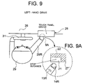
- This arrangement of the display areas 21 and touch areas 22 is considered to be advantageous when the vehicle is a left-hand drive vehicle as shown in Fig. 9.
- the touch panel device 18 is mounted at the center of the console 26. When the driver 29 is seated, the touch panel device is located at the right front of the driver 29. The touch panel device 18 is above the elbow of the seated driver.
- the driver 29 When the driver 29 operates the electronic device 28, the driver 29 generally uses the index finger or the middle finger 13R of his right hand to touch the touch panel device 18.
- the finger 13R moves from the lower left side of the touch panel device 18 towards the touch panel device 18.
- the shaded area 27' extends in the upper and right peripheral areas of the display area 21. If the touch panel screen is simultaneously touched by the finger 13R and the nail 14R as shown in Fig.2, the middle point C between the two touched points A and B falls in the shaded area 27'.
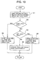
- the main controller 30 of the touch panel device 18 performs the matching operation. Specifically, the main controller 30 calculates the ratio of the resolution of the display layer in the display part 23 to the output resolution of the touch sensor layer in the touch switch part 24. The main controller 30 then conforms the display area 21 with the touch area 22, using the calculated resolution ratio. In order to maintain the relative positional relationship between each pair of display area 21 and touch area 22 on the display panel 20 during the operation of the touch panel device 18, a process shown in Fig. 10 is performed within a common calibration process implemented in the touch panel device 18.
- the main controller 30 of the touch panel device 18 receives the information of the desired relationship between the display areas 21 and the touch areas 22 from the system memory 50 (Step S1). Then, the main controller 30 determines whether the vehicle is a right-hand drive (Step S2). If the vehicle is right-hand drive, the main controller 30 maintains the touch area 22 in the upper left offset position (Step S4). If the vehicle is a left-hand drive (Yes at Step S3), the main controller 30 maintains the touch area 22 in the upper right offset position (Step S5). If the steering wheel 31 of the vehicle is located in the middle of the vehicle, the touch area 22 is not offset from the associated display area 21 (Step S6), as shown in Fig. 1.
- Step S1 The information of the desired relationship between the display areas 21 and the touch areas 22 (Step S1) may be input into a nonvolatile RAM of the system memory 50 by the driver using the arrangement command entry unit 70. Alternatively, the information may be entered by a serviceman of an automobile dealer when the vehicle is purchased, as an initial setting of the touch panel device 18.
- the touch area 22 is offset to the upper left direction or the upper right direction in the illustrated embodiments, the present invention is not limited in this regard. Specifically, the touch area 22 can be offset in any direction (to the right, the left, the lower right, the lower left, or downwards) relative to the associated display area 21, depending upon the positional relationship between the touch panel device user and the touch panel device. Further, the touch areas 22 may be fixed and the display areas 21 may be shifted.
- the display areas 21 and/or the touch areas 22 may be changed in size and/or shape. That is, at least either the relative positional relationship or the relative size relationship between the display areas and touch areas is adjustable in this invention. The change made to the relative relationship between the display areas and touch areas may be determined based on ergonomics.
Landscapes
- Engineering & Computer Science (AREA)
- General Engineering & Computer Science (AREA)
- Theoretical Computer Science (AREA)
- Human Computer Interaction (AREA)
- Physics & Mathematics (AREA)
- General Physics & Mathematics (AREA)
- Position Input By Displaying (AREA)
- Navigation (AREA)
- Push-Button Switches (AREA)
- Traffic Control Systems (AREA)
- Instrument Panels (AREA)
- User Interface Of Digital Computer (AREA)
Applications Claiming Priority (2)
| Application Number | Priority Date | Filing Date | Title |
|---|---|---|---|
| JP2002153227 | 2002-05-28 | ||
| JP2002153227A JP2003344086A (ja) | 2002-05-28 | 2002-05-28 | タッチパネル装置及び自動車用表示入力装置 |
Publications (1)
| Publication Number | Publication Date |
|---|---|
| EP1378818A2 true EP1378818A2 (de) | 2004-01-07 |
Family
ID=29561292
Family Applications (1)
| Application Number | Title | Priority Date | Filing Date |
|---|---|---|---|
| EP03009937A Withdrawn EP1378818A2 (de) | 2002-05-28 | 2003-04-30 | Berührungsempfindliche Tafel |
Country Status (3)
| Country | Link |
|---|---|
| US (1) | US7154483B2 (de) |
| EP (1) | EP1378818A2 (de) |
| JP (1) | JP2003344086A (de) |
Families Citing this family (73)
| Publication number | Priority date | Publication date | Assignee | Title |
|---|---|---|---|---|
| US7808479B1 (en) | 2003-09-02 | 2010-10-05 | Apple Inc. | Ambidextrous mouse |
| US20010033243A1 (en) | 2000-03-15 | 2001-10-25 | Harris Glen Mclean | Online remote control configuration system |
| US8531276B2 (en) | 2000-03-15 | 2013-09-10 | Logitech Europe S.A. | State-based remote control system |
| US6784805B2 (en) * | 2000-03-15 | 2004-08-31 | Intrigue Technologies Inc. | State-based remote control system |
| FI112119B (fi) * | 2002-06-25 | 2003-10-31 | Nokia Corp | Menetelmä ohjauskomennon tulkitsemiseksi ja kannettava elektroninen laite |
| US7656393B2 (en) | 2005-03-04 | 2010-02-02 | Apple Inc. | Electronic device having display and surrounding touch sensitive bezel for user interface and control |
| US11275405B2 (en) | 2005-03-04 | 2022-03-15 | Apple Inc. | Multi-functional hand-held device |
| US7116314B2 (en) * | 2003-05-06 | 2006-10-03 | International Business Machines Corporation | Method for distribution wear for a touch entry display |
| JP2005266215A (ja) * | 2004-03-18 | 2005-09-29 | Toshiba Matsushita Display Technology Co Ltd | 液晶表示装置および抵抗検出式タッチパネル |
| JP4148187B2 (ja) * | 2004-06-03 | 2008-09-10 | ソニー株式会社 | 携帯型電子機器、入力操作制御方法及びそのプログラム |
| JP2006012262A (ja) * | 2004-06-24 | 2006-01-12 | Alpine Electronics Inc | 電子機器及びその媒体排出方法 |
| US7576733B2 (en) * | 2004-07-12 | 2009-08-18 | Gtech Rhode Island Corporation | Touch screen image setting frame |
| JP4506331B2 (ja) * | 2004-07-27 | 2010-07-21 | マツダ株式会社 | 車両用スイッチ表示装置 |
| JP2006061310A (ja) * | 2004-08-25 | 2006-03-09 | Pentax Corp | タッチパネル及び内視鏡装置のプロセッサ |
| US7168751B2 (en) * | 2004-09-20 | 2007-01-30 | Lear Corporation | Automotive center stack panel with contact-less switching |
| JP2006134184A (ja) * | 2004-11-08 | 2006-05-25 | Honda Access Corp | 遠隔制御スイッチ |
| JP5550211B2 (ja) * | 2005-03-04 | 2014-07-16 | アップル インコーポレイテッド | 多機能ハンドヘルド装置 |
| TWI270025B (en) * | 2005-03-21 | 2007-01-01 | Au Optronics Corp | Dual emission display with integrated touch screen and fabricating method thereof |
| DE102006018238A1 (de) | 2005-04-20 | 2007-03-29 | Logitech Europe S.A. | System und Verfahren zur adaptiven Programmierung einer Fernbedienung |
| US7903090B2 (en) | 2005-06-10 | 2011-03-08 | Qsi Corporation | Force-based input device |
| US7337085B2 (en) * | 2005-06-10 | 2008-02-26 | Qsi Corporation | Sensor baseline compensation in a force-based touch device |
| US8542196B2 (en) * | 2005-07-22 | 2013-09-24 | Move Mobile Systems, Inc. | System and method for a thumb-optimized touch-screen user interface |
| US20070035524A1 (en) * | 2005-08-09 | 2007-02-15 | Sony Ericsson Mobile Communications Ab | Methods, electronic devices and computer program products for controlling a touch screen |
| US8122259B2 (en) | 2005-09-01 | 2012-02-21 | Bricom Technologies Ltd | Systems and algorithms for stateless biometric recognition |
| EP2590056B1 (de) * | 2005-09-14 | 2018-10-31 | Ntt Docomo, Inc. | Mobiles Endgerät und in einem mobilen Endgerät verwendetes Programm |
| JP2007233257A (ja) * | 2006-03-03 | 2007-09-13 | Sanyo Electric Co Ltd | 表示装置 |
| US20070222767A1 (en) * | 2006-03-22 | 2007-09-27 | David Wang | Glide touch sensor based interface for navigation infotainment systems |
| US20070222764A1 (en) * | 2006-03-22 | 2007-09-27 | Centrality Communications, Inc. | Glide touch sensor based interface for navigation infotainment systems |
| US7777732B2 (en) * | 2007-01-03 | 2010-08-17 | Apple Inc. | Multi-event input system |
| JP4858206B2 (ja) * | 2007-02-09 | 2012-01-18 | アイシン・エィ・ダブリュ株式会社 | 車載機器の操作支援装置、操作支援方法 |
| JP4464985B2 (ja) * | 2007-04-27 | 2010-05-19 | ビステオン・ジャパン株式会社 | El発光式タッチスイッチ |
| EP2145245A4 (de) * | 2007-05-09 | 2013-04-17 | Adapx Inc | Digitale papierprodukte und verfahren in zusammenhang damit |
| WO2008147917A2 (en) * | 2007-05-22 | 2008-12-04 | Qsi Corporation | Touch-based input device with boundary defining a void |
| US7995038B2 (en) * | 2007-09-28 | 2011-08-09 | GM Global Technology Operations LLC | Software flow control of rotary quad human machine interface |
| US9092134B2 (en) * | 2008-02-04 | 2015-07-28 | Nokia Technologies Oy | User touch display interface providing an expanded selection area for a user selectable object |
| US8681093B2 (en) * | 2008-02-11 | 2014-03-25 | Apple Inc. | Motion compensation for screens |
| DE102008029446B4 (de) * | 2008-06-20 | 2024-08-08 | Bayerische Motoren Werke Aktiengesellschaft | Verfahren zur Steuerung von Funktionen in einem Kraftfahrzeug mit benachbart liegenden Bedienelementen |
| TW201005599A (en) * | 2008-07-18 | 2010-02-01 | Asustek Comp Inc | Touch-type mobile computing device and control method of the same |
| DE102008058566A1 (de) * | 2008-11-21 | 2010-05-27 | Continental Automotive Gmbh | Haptische Bedieneinrichtung |
| DE102008058568A1 (de) * | 2008-11-21 | 2010-05-27 | Continental Automotive Gmbh | Haptische Bedieneinrichtung |
| US9195365B2 (en) * | 2009-03-25 | 2015-11-24 | Honeywell International Inc. | Automatic configurator of display objects |
| US8375402B2 (en) * | 2009-03-25 | 2013-02-12 | Honeywell International Inc. | Mechanism for interfacing a display screen of another technology with a computing platform |
| US20100251150A1 (en) * | 2009-03-25 | 2010-09-30 | Honeywell International Inc. | System for defining a user interface of a remote display device |
| US20100251233A1 (en) * | 2009-03-25 | 2010-09-30 | Honeywell International Inc. | Embedded computing system user interface emulated on a separate computing device |
| US20100245259A1 (en) * | 2009-03-25 | 2010-09-30 | Honeywell International Inc. | Small screen display with a data filtering and sorting user interface |
| US20100251184A1 (en) | 2009-03-25 | 2010-09-30 | Honeywell International Inc. | Approach for advanced user navigation |
| JP2011138185A (ja) * | 2009-12-25 | 2011-07-14 | Nikon Corp | 表示装置及び電子機器 |
| US8988367B2 (en) * | 2010-02-05 | 2015-03-24 | Broadcom Corporation | Systems and methods for providing enhanced touch sensing |
| US8456445B2 (en) * | 2010-04-30 | 2013-06-04 | Honeywell International Inc. | Touch screen and method for adjusting screen objects |
| JP5676608B2 (ja) * | 2010-06-29 | 2015-02-25 | 富士フイルム株式会社 | 立体表示装置、立体撮影装置、および指示判定方法 |
| US8508401B1 (en) | 2010-08-31 | 2013-08-13 | Logitech Europe S.A. | Delay fixing for command codes in a remote control system |
| US8730194B2 (en) | 2011-09-26 | 2014-05-20 | Nano Nails, LLC | Finger stylus for use with capacitive touch panels |
| US9213482B2 (en) * | 2011-11-11 | 2015-12-15 | Elan Microelectronics Corporation | Touch control device and method |
| TWI451309B (zh) * | 2011-11-11 | 2014-09-01 | Elan Microelectronics Corp | Touch device and its control method |
| US9268430B2 (en) | 2011-12-14 | 2016-02-23 | Sony Corporation | Information processing apparatus, information processing method, program, and information storage medium |
| KR101991493B1 (ko) * | 2012-01-17 | 2019-06-20 | 삼성전자주식회사 | 터치 인터페이스를 제공하는 방법, 기계로 읽을 수 있는 저장 매체 및 휴대 단말 |
| JP5641367B2 (ja) * | 2012-03-19 | 2014-12-17 | アイシン・エィ・ダブリュ株式会社 | 操作入力システム |
| US20140062917A1 (en) * | 2012-08-29 | 2014-03-06 | Samsung Electronics Co., Ltd. | Method and apparatus for controlling zoom function in an electronic device |
| US20140184511A1 (en) * | 2012-12-28 | 2014-07-03 | Ismo Puustinen | Accurate data entry into a mobile computing device |
| DE102013004251B4 (de) | 2013-03-12 | 2018-05-09 | Audi Ag | Verfahren zum Betreiben eines Bediensystems und Kraftwagen mit einem solchen Bediensystem |
| WO2015030795A1 (en) | 2013-08-30 | 2015-03-05 | Hewlett Packard Development Company, L.P. | Touch input association |
| US10649557B2 (en) | 2013-12-10 | 2020-05-12 | Pas Deutschland Gmbh | Method for operator guidance, control panel component, production of a control panel component and home appliance comprising a control panel component |
| DE102013113772A1 (de) * | 2013-12-10 | 2015-06-11 | Pas Deutschland Gmbh | Verfahren zur Bedienerführung, Blendenbauteil, Herstellung eines Blendenbauteils sowie Haushaltsgerät mit einem Blendenbauteil |
| JP5899251B2 (ja) * | 2014-01-29 | 2016-04-06 | 本田技研工業株式会社 | 車両用入力装置 |
| US10126940B2 (en) * | 2014-10-19 | 2018-11-13 | Lenovo (Singapore) Pte. Ltd. | Touch zones on a soft keyboard |
| US10055121B2 (en) | 2015-03-07 | 2018-08-21 | Apple Inc. | Activity based thresholds and feedbacks |
| KR101755913B1 (ko) * | 2015-12-03 | 2017-07-07 | 현대자동차주식회사 | 스티어링 휠을 이용한 차량 내 기기 조작 장치 및 그 방법 |
| JP6928127B2 (ja) * | 2016-03-01 | 2021-09-01 | マクセル株式会社 | ウェアラブル情報端末 |
| US10860199B2 (en) | 2016-09-23 | 2020-12-08 | Apple Inc. | Dynamically adjusting touch hysteresis based on contextual data |
| JP2019156263A (ja) * | 2018-03-15 | 2019-09-19 | 株式会社東海理化電機製作所 | 操作位置検出装置 |
| CN112829585A (zh) * | 2021-03-03 | 2021-05-25 | 上海科世达-华阳汽车电器有限公司 | 一种车辆方向盘开关、车辆方向盘开关控制方法和介质 |
| CN116540862B (zh) * | 2022-01-26 | 2023-12-01 | 荣耀终端有限公司 | 触控操作响应方法和电子设备 |
| US12368470B2 (en) * | 2023-04-17 | 2025-07-22 | Ford Global Technologies, Llc | Placement of mobile wireless device on a display panel with a hidden antenna |
Family Cites Families (6)
| Publication number | Priority date | Publication date | Assignee | Title |
|---|---|---|---|---|
| ATE188302T1 (de) * | 1993-04-01 | 2000-01-15 | Ibm | Dynamische anpassungseinrichtung für berührungsanzeigeknöpfe |
| DE4406668C2 (de) * | 1993-04-27 | 1996-09-12 | Hewlett Packard Co | Verfahren und Vorrichtung zum Betreiben eines berührungsempfindlichen Anzeigegeräts |
| DE69524340T2 (de) * | 1994-09-22 | 2002-08-14 | Aisin Aw Co | Berührungsanzeige für ein Informationseingabesystem |
| US5818451A (en) * | 1996-08-12 | 1998-10-06 | International Busienss Machines Corporation | Computer programmed soft keyboard system, method and apparatus having user input displacement |
| DE19638015A1 (de) * | 1996-09-18 | 1998-03-26 | Mannesmann Vdo Ag | Verfahren zur Erzeugung von haptischen Markierungen auf einer Eingabefläche und Anordnung zur Durchführung des Verfahrens |
| US6256021B1 (en) * | 1998-09-15 | 2001-07-03 | Ericsson Inc. | Apparatus and method of configuring target areas within a touchable item of a touchscreen |
-
2002
- 2002-05-28 JP JP2002153227A patent/JP2003344086A/ja active Pending
-
2003
- 2003-04-25 US US10/422,761 patent/US7154483B2/en not_active Expired - Fee Related
- 2003-04-30 EP EP03009937A patent/EP1378818A2/de not_active Withdrawn
Also Published As
| Publication number | Publication date |
|---|---|
| JP2003344086A (ja) | 2003-12-03 |
| US20030222858A1 (en) | 2003-12-04 |
| US7154483B2 (en) | 2006-12-26 |
Similar Documents
| Publication | Publication Date | Title |
|---|---|---|
| US7154483B2 (en) | Touch panel device | |
| US8487882B2 (en) | Touch-panel display device and portable equipment | |
| US8799803B2 (en) | Configurable input device | |
| US9870065B2 (en) | Information display apparatus with proximity detection performance and information display method using the same | |
| JP4245512B2 (ja) | 入力装置 | |
| US6597384B1 (en) | Automatic reorienting of screen orientation using touch sensitive system | |
| US9292120B2 (en) | Electronic device and operation method thereof | |
| US20070165006A1 (en) | Input device and electronic apparatus | |
| US20020180620A1 (en) | Three-dimensional contact-sensitive feature for electronic devices | |
| EP2148267B1 (de) | Mobile Vorrichtung mit Berührungsbildschirm und Verfahren zum Einstellen einer virtuellen Tastatur dafür | |
| US20130079139A1 (en) | Overlays for touch sensitive screens to simulate buttons or other visually or tactually discernible areas | |
| JP2006059238A (ja) | 情報入力表示装置 | |
| JP3382506B2 (ja) | ディスプレイ装置 | |
| US20110025718A1 (en) | Information input device and information input method | |
| US7479903B2 (en) | Input device using elastic material | |
| KR20170108001A (ko) | 정보 처리 장치, 입력 장치, 정보 처리 장치의 제어 방법, 입력 장치의 제어 방법 및 프로그램 | |
| JP2014016743A (ja) | 情報処理装置、情報処理装置の制御方法、および情報処理装置の制御プログラム | |
| US20120092275A1 (en) | Information processing apparatus and program | |
| JP2006350789A (ja) | タッチパネル付き表示装置 | |
| JPH0683537A (ja) | タッチパネル式情報処理装置 | |
| JP2008009856A (ja) | 入力装置 | |
| US9128559B2 (en) | Electronic device | |
| US20190102050A1 (en) | Display control device | |
| JP2019128707A (ja) | 表示入力装置 | |
| JP2004227233A (ja) | タッチパネル装置 |
Legal Events
| Date | Code | Title | Description |
|---|---|---|---|
| PUAI | Public reference made under article 153(3) epc to a published international application that has entered the european phase |
Free format text: ORIGINAL CODE: 0009012 |
|
| AK | Designated contracting states |
Kind code of ref document: A2 Designated state(s): AT BE BG CH CY CZ DE DK EE ES FI FR GB GR HU IE IT LI LU MC NL PT RO SE SI SK TR |
|
| AX | Request for extension of the european patent |
Extension state: AL LT LV MK |
|
| STAA | Information on the status of an ep patent application or granted ep patent |
Free format text: STATUS: THE APPLICATION IS DEEMED TO BE WITHDRAWN |
|
| 18D | Application deemed to be withdrawn |
Effective date: 20091031 |