EP1376987B1 - Kommunikationsvorrichtung um andere Knoten zu managen - Google Patents
Kommunikationsvorrichtung um andere Knoten zu managen Download PDFInfo
- Publication number
- EP1376987B1 EP1376987B1 EP20030102591 EP03102591A EP1376987B1 EP 1376987 B1 EP1376987 B1 EP 1376987B1 EP 20030102591 EP20030102591 EP 20030102591 EP 03102591 A EP03102591 A EP 03102591A EP 1376987 B1 EP1376987 B1 EP 1376987B1
- Authority
- EP
- European Patent Office
- Prior art keywords
- node
- dominated
- dominating
- communication apparatus
- upper layer
- Prior art date
- Legal status (The legal status is an assumption and is not a legal conclusion. Google has not performed a legal analysis and makes no representation as to the accuracy of the status listed.)
- Expired - Lifetime
Links
Images


Classifications
-
- H—ELECTRICITY
- H04—ELECTRIC COMMUNICATION TECHNIQUE
- H04L—TRANSMISSION OF DIGITAL INFORMATION, e.g. TELEGRAPHIC COMMUNICATION
- H04L41/00—Arrangements for maintenance, administration or management of data switching networks, e.g. of packet switching networks
-
- H—ELECTRICITY
- H04—ELECTRIC COMMUNICATION TECHNIQUE
- H04L—TRANSMISSION OF DIGITAL INFORMATION, e.g. TELEGRAPHIC COMMUNICATION
- H04L49/00—Packet switching elements
- H04L49/60—Software-defined switches
- H04L49/602—Multilayer or multiprotocol switching, e.g. IP switching
-
- H—ELECTRICITY
- H04—ELECTRIC COMMUNICATION TECHNIQUE
- H04L—TRANSMISSION OF DIGITAL INFORMATION, e.g. TELEGRAPHIC COMMUNICATION
- H04L9/00—Cryptographic mechanisms or cryptographic arrangements for secret or secure communications; Network security protocols
- H04L9/40—Network security protocols
-
- H—ELECTRICITY
- H04—ELECTRIC COMMUNICATION TECHNIQUE
- H04L—TRANSMISSION OF DIGITAL INFORMATION, e.g. TELEGRAPHIC COMMUNICATION
- H04L49/00—Packet switching elements
- H04L49/35—Switches specially adapted for specific applications
- H04L49/351—Switches specially adapted for specific applications for local area network [LAN], e.g. Ethernet switches
Definitions
- the present invention relates to a communication system having dominating nodes and dominated nodes, and more particularly to a dominating node capable of managing other nodes and a dominated node to be dominated by the dominating node.
- IEEE1394 is known as the standards of a serial interface capable of large capacity high speed data transfer.
- An interface complied with the IEEE1394 standards and an apparatus having this interface (hereinafter collectively called an IEEE 1394 device) constitute one node having hardware IEEE1394 bus protocols (lower layer) and software protocols (upper layer) for device control, isochronous transmission control and the like.
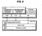
- Fig. 9 is a conceptual diagram showing an example of a protocol stack of a general audio visual (AV) apparatus having an mLAN (trademark) upperlayer.
- the mLAN standards are complied with the IEEE1394 standards and are an application at a higher level than the IEEE1394 standards, constituting a digital network system for music.
- the lower layer is constituted of, for example, a physical layer, a link layer, a transaction layer, and a serial bus management layer.
- the physical layer defines physical and electrical interfaces.
- the physical layer is generally made of hardware.
- the link layer provides one-way transmission service called sub-action and packet transmission/reception service (packet handler). Similar to the physical layer, the link layer is also generally made of hardware.
- the link layer provides, for example, synchronous transmission and isochronous transmission services.
- Isochronous transmission is used for signals requiring high speed processing such as audio signals and video signals.
- the link layer of hardware provides all services of the isochronous transmission.
- the transaction layer deals with synchronous transmission.
- the transaction is a data transmission of a request-response type.
- the read transaction is used for reading data from a specific target address space.
- the write transaction is used for writing data in a specific target address space.
- the lock transaction is used for renewing data in a specific target address space in accordance with reference data.
- the serial bus management layer is a module for concentrically managing resources on the bus.
- the bus management includes management of power supplies, management of a topology map and a speed map, management of isochronous resources, and the like.
- the upper layer is software for managing the lower layer and the whole node, and is constituted of, for example, the 1394AV protocols (IEC-61883) and mLAN upper layer.
- the 1394AV protocols define a common isochronous packet (CIP) format for expressing the data contents of an isochronous packet, a connection management protocol (CMP) for managing connections by defining a virtual "plug", a function control protocol (FCP) for managing other devices connected to the IEEE1394 bus, and the like.
- CIP common isochronous packet
- CMP connection management protocol
- FCP function control protocol
- the mLAN upper layer is a protocol layer for transmission of audio/music information in accordance with the IEEE1394 standards.
- the mLAN upper layer is constituted of an audio/music information transmission protocol and a connection management protocol both complied with the 1394AV protocols.
- the audio/music information transmission protocol is used for adding the format for transmitting audio/music information to the definition of CIP.
- the connection management protocol is used for performing autonomous connection management of each node by using an intelligent CMP.
- All IEEE1394 devices connected to an IEEE1394 bus have the upper and lower layers although the functions thereof are different more or less.
- the upper layer is more complicated than the lower layer. Therefore, hardware resources necessary for the upper layer increase more than the lower layer. The manufacture cost rises if the upper layer is used for all IEEE1394 devices.
- the upper layer is more relevant to a user interface than the lower layer. There are, therefore, many chances of feeding back revision requests from users. Although it is desired that the upper layer has the structure easy to match a new specification, the manufacture cost rises if the structure of the upper layer of each of all IEEE1394 devices is made easy to upgrade.
- An object of this invention is to provide an apparatus complied with the IEEE1394 standards and capable of being manufactured at a low cost.
- Another object of this invention is to provide an apparatus complied with the IEEE1394 standards and capable of managing other nodes.
- Fig. 1 is a block diagram showing an example of an IEEE1394 bus 1 according to an embodiment of the invention.
- the IEEE1394 bus 1 of the embodiment is structured by connecting, with IEEE1394 cables, general nodes 2a and 2b with their upper and lower layers, a dominated node 3a without an upper layer, and a dominating node 4 with its upper and lower layers and upper layers of other nodes (e.g., upper layers of the dominated nodes 3a and 3b).
- Each of the general nodes 2a and 2b may be one of an electronic musical instrument, an acoustic machine, an AV apparatus, a personal computer, an external storage device of various types and the like each having an IEEE1394 interface.
- the general node 2a has the upper layer A and lower layer A
- the general node 2b has the upper layer E and lower layer E.
- the dominated node 3a may be one of an electronic musical instrument, an acoustic machine, an AV apparatus, a personal computer, an external storage device of various types and the like each having an IEEE1394 interface.
- the dominated node 3a may be a powered speaker or the like.
- the dominated node 3a has no upper layer, but it is provided with only the lower layer B. Since the dominated node 3a does not have an upper layer, the dominated node 3a itself cannot normally communicate with the general node 2a or 2b by using a protocol defined by the upper layer.
- the dominated node 3a Since the dominated node 3a is not provided with the upper layer, it cannot process by itself a command based upon the 1394AV protocol and a command based upon the mLAN standards which commands are generally processed by the upper layer. Since various transactions, isochronous transmission and the like are processed by the lower layer, the dominated node 3a itself can process them.
- the dominated node 3a is a powered speaker
- voice signals and the like to be reproduced are generally transmitted through isochronous transmission so that they can be processed only by the lower layer.
- connection setting of a reception channel, volume control and the like cannot be processed by the dominated node 3a itself with only the lower layer, because a command is received by the upper layer and the upper layer writes data in a function register in the lower layer corresponding to the command by analyzing the command.
- the dominated node 3a is a terminal node and stores an ID for identifying the type of an upper layer necessary for the dominating node that dominates the dominated node into a Control and Status Registers (CSR) memory to be described later.
- the dominated node 3a also stores a Global Unique Identifier (GUID) of the dominating node currently dominating the terminal node in the CSR memory.
- GUID Global Unique Identifier
- the dominating node 4 may be one of an electronic musical instrument, an acoustic machine, an AV apparatus, a personal computer, an external storage device of various types and the like each having an IEEE1394 interface.
- the dominating node 4 is a personal computer having an external storage device.
- the dominating node 4 has its lower layer C and upper layer C and in addition to the upper layers B and D for managing the lower layers of the dominated nodes 3a and 3b. These upper layers B and D are used as the proxies of the upper layers of the dominated nodes 3a and 3b so that the dominated node 3a or 3b can communicate with the general node 2a or 2b by using the protocol defined by the upper layer.
- the dominating node 4 stores a GUID of a dominated node that the dominating node can dominate, in correspondence with software (upper layer) for managing the dominated node.
- the structure of the dominated node 3b is approximately the same as that of the dominated node 3a, excepting that the dominated node 3b has an upper layer D' and the lower layer D.
- the dominated node 3b may suspend the function of its upper layer D' to be managed by the upper layer D of the dominating node 4.
- the upper layer D' of the dominated node 3b may manage only some functions and missing functions may be managed by the upper layer D of the dominating node 4. Functions of the upper layer D' of the dominated node 3b can be executed or suspended in response to an external command.
- the dominated node 3b is a terminal node and stores an ID for identifying the type of an upper layer in the CSR memory, ID being necessary for the dominating node that manages the dominated node. If functions of the upper layer D' of the dominated node 3b are to be suspended, the dominated node 3b stores a GUID of the dominating node currently managing the dominated node in the CSR memory.
- Fig. 2 is a conceptual diagram showing an example of the CSR memory of the dominated node 3a or 3b according to the embodiment.
- the CSR memory of the dominated node 3a or 3b is constituted of, for example, a CSR core register, a serial bus register, a configuration-ROM having Y address information, and node-specific registers having an AV/C area and a Y area.
- the CSR core register and serial bus register have the structure similar to that of a known IEEE1394 device.
- the Y address information is made public to other nodes (particularly the dominating node).
- the Y address information includes the addresses of a read-only area and a read/write area respectively in the Y area, and the addresses of a dominating node ID, a lower layer function register area and other areas respectively in the read/write area.
- a GUID of the dominating node managing the dominated node is stored in the dominating node ID.
- a node (dominating node) whose GUID is stored in the dominating node ID reads this Y address information so that the dominating node can detect the addressees of registers necessary for managing the dominated node.
- Fig. 3 is a conceptual diagram showing an example of the CSR memory of the dominating node 4 according to the embodiment.
- the CSR memory of the dominating node 4 is constituted of, for example, a CSR core register, a serial bus register, a configuration-ROM, and node-specific registers having an AV/C area.
- the CSR core register and serial bus register have the structure similar to that of a known IEEE1394 device.
- the structure of other parts is generally the same as that of the CSR memory of the dominated node 3a or 3b shown in Fig. 2.
- the CSR memory of the dominating node 4 features in that it stores information of the dominating node in the configuration-ROM as well as function information of dominated nodes under management of the dominating node. Since the function information of each dominated node under management is stored in the configuration-ROM, the other node connected to the network interprets as if the dominating node features the functions of the dominated node.
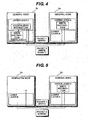
- Fig. 4 is a block diagram illustrating communications between the general nodes 2a and 2b.
- the general node 2b receives from the general node 2a (on the transmission side) a write-command instruction (packet 1) relative to an address corresponding to a function of the upper layer E.
- a write-command instruction packet 1
- the lower layer E of the general node 2b executes the write-command relative to the address corresponding to the function of the upper layer E.
- the upper layer E of the general node 2b acknowledges the write instruction (packet 1) and supplies the lower layer E with the write instruction relative to a register (function register) corresponding to the command. Namely, the upper layer E analyzes the received command to allow control data corresponding to the contents of the command to be written in the register (function register) of the lower layer E corresponding to the function to be managed by the command. With the above-described operations, the lower layer E can perform the operation corresponding to the command transmitted from the general node 2a, in accordance with the control data written in the register.
- the lower layer E of the general node 2b transmits a packet 2 to the general node 2a, the packet 2 indicating that the write instruction was executed normally.
- the nodes having the upper layer can manage each other by writing data in the function register via their own upper layers.
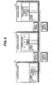
- Fig. 5 is a block diagram illustrating communications between the general node 2a and dominated node 3a according to the embodiment. In this example, it is assumed that the dominating node 4 is not connected to the IEEE1394 bus 1.
- the dominated node 3a receives, from the general node 2a (on the transmission side), a write-command instruction (packet 1) relative to the address corresponding to a function of the upper layer.
- a write-command instruction packet 1
- the lower layer B of the dominated node 3a (on the reception side) tries to execute the write-command.
- the lower layer B transmits an error (packet 2) to the general node 2a.
- the write-command corresponding to the received packet 1 fails so that the control of the lower layer B corresponding to the command will not be performed.
- the dominated node 3a Since the dominated node 3a returns the error relative to the command corresponding to the function of the upper layer, it can know that the dominated node 3a is not provided with the upper layer.
- the dominating node 4 is provided with the upper layer of the dominated node 3a and communicates with the general node 2a as a proxy of the dominated node 3a.
- Fig. 6 is a block diagram showing communications between the general node 2a and dominated node 3a via the dominating node 4 according to the embodiment.
- the dominating node 4 can manage the dominated node 3a because the dominating node 4 has already been set by a dominated node management setting process to be later described.
- the lower layer C of the dominating node 4 receives from the general node 2a (on the requesting side) a write-command instruction (packet 1) relative to an address corresponding to a function of the upper layer B of the dominated node 3a.
- the lower layer C of the dominating node 4 writes a command relative to the address corresponding to the function of the upper layer B.
- the upper layer B detects the address of a function register of the lower layer B of the dominated node 3a corresponding to the function designated by the command.
- a write instruction (packet 2) for control data corresponding to the command relative to the detected address is transmitted to the dominated node 3a.
- the lower layer B of the dominated node 3a executes the received write instruction (packet 2). Namely, the control data is written relative to the address corresponding to the function register of the lower layer B, and the process result (packet 3) is transmitted to the dominating node 4. In accordance with the written control data, the lower layer B executes an operation corresponding to the command transmitted from the general node 2a to the upper layer B of the dominating node 4.
- the dominating node Upon reception of the process result (packet 3) from the dominated node 3a, the dominating node transmits a response (packet 4) to the command to the general node 2a that is the requesting side and sent the command.
- the general node 2a receives the response (packet 4) from the dominating node 4 and recognizes that the process was performed normally.
- the dominating node 4 becomes a proxy of the role that the upper layer of a dominated node originally plays.
- a signal to be processed at the upper layer is transmitted to the dominated node by using the format that the lower layer can process. In this manner, a write-command or the like relative to the dominated node without the upper layer can be performed.
- Fig. 7 is a flow chart illustrating a dominated node management setting process to be executed by the dominating node 4. This dominated node management setting process is activated each time a normal bus reset is executed. The bus reset occurs when the topology changes such as when a new node is connected to the bus and when the connected node is disconnected from the bus.
- Step SA1 the dominated node management setting process starts and the flow advances to the next Step SA2.
- Step SA2 the dominated node management setting process is initialized. For example, the functions and the like of each dominated node described in the configuration-ROM of the dominating node are cleared. Thereafter, the flow advances to the next Step SA3.
- GUID of each dominated node to be managed is read from a rewritable memory (e.g., the read/write area in Fig. 2).
- a rewritable memory e.g., the read/write area in Fig. 2.
- the dominating node of this embodiment has already memorized one GUID of a dominated node in the rewritable memory.
- the dominating node may memorize one GUID, a plurality of GUID's or no GUID of the dominated node(s).
- GUID of the dominated node to be managed may be input by a user.
- GUID of the dominated node, which received the write instruction relative to the address corresponding to the function of the upper layer and returned the error as shown in Fig. 5, may be read from the configuration-ROM of the dominated node.
- the flow advances to the next Step SA4.
- Step SA4 GUID of each node connected to the IEEE1394 bus 1 is read. Although only one GUID is read by this Step SA4, GUID's of all nodes are will be read by repeating Step SA4. Thereafter, the flow advances to the next Step SAB.
- Step SA5 it is checked whether GUID read at Step SA3 of the dominated node to be managed is equal to GUID read at Step SA4. If equal, the flow advances to Step SA6 indicated by a YES arrow, whereas if not, the flow skips to Step SA10 indicated by a NO arrow.
- Step SA6 information necessary for managing the dominated node having the same GUID as that read at Step SA4 is read from the configuration-ROM of the dominated node. Thereafter, the flow advances to the next Step SA7.
- Step SA7 in accordance with the information read at Step SA6, a software instance (an upper layer of the dominated node to be managed) corresponding to the dominated node is created in the upper layer of the dominating node. Thereafter, the flow advances to the next Step SA8.
- Creating the software instance corresponding to the dominated node is to set the state of the dominating node so as to allow the upper node of the dominating node to acknowledge the command (such as an AV/C command) which the upper layer of the dominated node should originally acknowledge. Namely, after this process at Step SA7, the dominating node can acknowledge a command transmitted from another node to the dominated node under management of the dominating node.
- the command such as an AV/C command
- Step SA8 GUID of the dominating node is written in the dominating node GUID storage area (FIG. 2) of the dominated node to indicate that the dominated node is managed by this dominating node. Thereafter, the flow advances to the next Step SA9.
- Step SA9 information of functions of the dominated node is additionally written in the configuration-ROM of the dominating node. It is therefore possible that another node can see transparently as if the dominating node has functions of the dominated node. Thereafter, the flow advances to the next Step SA10.
- Functions corresponding to the upper layer of a dominated node to be managed (the upper layer of a dominated node connected to the bus) among the upper layers prepared in advance by the dominating node are written in the configuration-ROM of the dominating node, but functions corresponding of the upper layer of a dominated node not to be managed (the upper layer of a dominated node not connected to the bus) are not written in the configuration-ROM.
- Step SA10 it is checked whether GUID's of all nodes connected to the IEEE1394 bus 1 are read. If read, the flow advances to Step SA11 indicated by a YES arrow, whereas if not, the flow returns to Step SA4 indicated by a NO arrow to repeat the succeeding Steps.
- Step SA11 a completion notice of dominated node management setting is issued to other nodes in order to make the other nodes recognize that the dominated node is already managed. Thereafter, the flow advances to the next Step SA12 whereat the dominated node management setting process is terminated.
- Step SA11 a bus reset may be issued to make other nodes connected to the same IEEE1394 bus 1 as that of the dominating node recognize the software instance created in the upper layer of the dominating node. In this case, the other nodes can see transparently as if there is a dominated node 3a with the upper layer.
- a command corresponding to a function of the upper layer of the dominated node to be managed is transmitted to the dominating node.
- the lower layer can directly process transmissions based on isochronous communications so that a command is directly transmitted to a dominated node without involving the dominating node.
- the dominating node can process all accesses to the upper layer of a dominated node under management of the dominating node, and if necessary, can issue a predetermined transaction to a corresponding dominated node to confirm or change the operation state of the dominated node.
- the dominating node executes the process shown in Fig. 7 in response to the generated bus reset. In this case, functions of the new dominated node are written in the configuration-ROM of the dominating node, or functions of the disconnected dominated node are erased from the configuration-ROM.
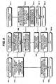
- Fig. 8 is a flow chart making easy to understand the concept of a process at each node during communications illustrated in Fig. 6. It is assumed that the dominating node has already executed the dominated node management setting process shown in Fig. 7. An arrow with a broken line shaft indicates a transmission of a packet.
- Steps SB1 to SB4 are processes to be executed at a request issuing side (the general node 2a shown in Fig. 6).
- Step SB1 the request issuing side process starts and the flow advances to the next Step SB2.
- Step SB2 a request for a software instance (the upper layer B of the dominating node 4 shown in Fig. 6) corresponding to a function of the dominated node is transmitted. Thereafter, the flow advances to the next Step SB3.
- the transmitted request is received by the dominating node at Step SB6 to be later described.
- Step SB3 the request issuing side receives a process result at the dominated node transmitted from the dominating node at Step SB9 to be described later. Thereafter, the flow advances to Step SB4 whereat the request issuing side process is terminated.
- Steps SB5 to SB10 are processes to be executed at the dominating node (the dominating node 4 shown in Fig. 6).
- Step SB5 the dominating node process starts and the flow advances to the next Step SB6.
- the dominating node receives the request for the software instance (the upper layer B of the dominating node 4 shown in Fig. 6) corresponding to the function of the dominated node and created in the upper layer of the dominating node. Thereafter, the flow advances to the next Step SB7.
- a write instruction is transmitted to the function register of the dominated node.
- the flow advances the next Step SB8.
- the dominating node stores the functions of each dominated node managed by the dominating node in the configuration-ROM.
- the dominating node also stores a variety of pieces of information for controlling each dominated node in a working memory of the dominating node. This information includes information of functions of each dominated node, an address of the function register of each dominated node corresponding to each function, and the like.
- the transmitted write instruction is received by the dominated node at Step SB12 to be described later.
- Step SB8 the dominating node receives the process result at the dominated node transmitted at Step SB14 to be described later. Thereafter, the flow advances to the next Step SB9.
- Step SB9 the process result at the dominated node received at Step SB8 is transmitted to the request issuing side. Thereafter, the flow advances to the next Step SB10 to terminate the dominating node process.
- Steps SB11 to SB15 are processes to be executed by the dominated node (the dominated node 3a shown in Fig. 6).
- Step SB11 the dominated node process starts and the flow advances to the next Step SB12.
- the dominated node receives the write instruction to the function register transmitted from the dominating node at Step SB7, and writes control data in the function register. Transmission/reception of the write instruction and a process based on the write instruction are performed by the transaction layer of the lower layer. Therefore, these operations can be performed normally by the dominated node without the upper layer. Thereafter, the flow advances to the next Step SB13.
- Step SB13 a function corresponding to the function register is executed. For example, predetermined values or the like are written in the function register. Thereafter, the flow advances to the next Step SB14.
- Step SB14 the process result of the write instruction is transmitted to the dominating node. Thereafter, the flow advances to the next Step SB15 to terminate the dominated node process.
- an IEEE1394 device serving as a dominating node can manage an apparatus (dominated node) complied with the IEEE1394 standards and without the upper layer.
- An IEEE1394 device corresponding to a general node can therefore control the dominated node via the dominating node.
- a single dominating node can manage a plurality of dominated nodes. It is therefore easy to update the upper layer complied with the IEEE1394 standards such as a user interface, without updating each apparatus separately and independently. Updating includes not only “updating an upper level protocol” but also “fixing bugs” and “improving the performance”.
- the upper layer is omitted from the dominated node, hardware and software resources necessary for the upper layer can be omitted, and the dominated node can be manufactured at a low cost.
- the dominated node can be managed by the dominating node.
- updating the upper layer of the dominating node is equivalent to updating the upper layer of the dominated node.
- the dominated node can be made complied with the new IEEE1394 standards only by updating the upper layer of the dominating node.
- the dominating node is a personal computer or the like capable of executing a plurality of software pieces (upper layers) for managing dominated nodes
- GUID of the dominated node managed by each software piece is managed and stored. In this manner, it becomes possible to avoid contention such as managing one dominated node by a plurality of software pieces.
- a plurality of dominating nodes may be connected to the IEEE1394 bus 1. If a plurality of dominating nodes are connected to the same IEEE1394 bus, it is necessary to arrange in such a manner that dominated nodes managed by respective dominating nodes are not duplicated.
- the functions of the embodiment may be realized by a commercially available computer installed with a computer program and the like realizing the embodiment functions.
- computer readable storage media such as a CD-ROM and a floppy disk storing the computer program and the like realizing the embodiment functions may be supplied to users.
- a computer is connected to a communication network such as a LAN, the Internet and telephone lines, the computer program and the like may be supplied via the communication network.
- a communication network such as a LAN, the Internet and telephone lines, the computer program and the like may be supplied via the communication network.
Landscapes
- Engineering & Computer Science (AREA)
- Computer Networks & Wireless Communication (AREA)
- Signal Processing (AREA)
- Computer Security & Cryptography (AREA)
- Small-Scale Networks (AREA)
- Information Transfer Systems (AREA)
Claims (8)
- Kommunikationsapparat, welcher als dominierter Knoten (3a) zum Kommunizieren mit einem zweiten Knoten, der als dominierender Knoten (4) dient und darin eine Ebenenstruktur eines Protokoll-Stapels besitzt, welche eine untere Ebene eines Protokollstapels und eine obere Ebene zusätzlich zu ihrer unteren Ebene umfaßt, dient, wobei der dominierte Knoten (3a), der dominierende Knoten (4) und ein weiterer Knoten (2a) zumindest einen Teil eines Netzwerks bilden,
wobei der dominierte Knoten (3a) darin eine Ebenenstruktur eines Protokoll-Stapels besitzt, welche zumindest eine untere Ebene eines Protokollstapels in dem Kommunikationsapparat umfaßt, welche darin ein Register besitzt, wobei der Betrieb der unteren Ebene von in dem Register gespeicherten Daten gesteuert wird, und wobei der Kommunikationsapparat folgendes aufweist:Kommunikationsmittel, welche in der unteren Ebene des dominierten Knotens (3a) enthalten sind, zum Senden/Empfangen eines Signals an/von dem weiteren Knoten (2a) und dem dominierenden Knoten (4),wobei der Kommunikationsapparat dadurch gekennzeichnet ist, daßder Kommunikationsapparat die untere Ebene umfaßt ohne eine aktive obere Ebene eines Protokollstapels zum Erzeugen eines Steuersignals gemäß der Anweisung eines von der aktiven oberen Ebene des weiteren Knotens (2a) definierten Protokolls und zum Schreiben des Steuersignals in das Register in der unteren Ebene zu besitzen,und daß der Kommunikationsapparat dazu ausgelegt ist, von dem dominierenden Knoten (4) gesteuert zu werden, welcher als Proxy des dominierten Knotens (3a) arbeitet, das Steuersignal gemäß einer von dem weiteren Knoten erzeugten Anweisung erzeugt, und das Steuersignal über das Netzwerk in das Register in der unteren Ebene des dominierten Knotens (3a) schreibt. - Kommunikationsapparat gemäß Anspruch 1, welcher ferner Benachrichtigungsmittel zum Benachrichtigen des dominierenden Knotens (4), daß der Kommunikationsapparat keine aktive obere Ebene besitzt, aufweist.
- Kommunikationsapparat gemäß Anspruch 1, welcher ferner Speichermittel zum Speichern von Identifizierungsinformation des Kommunikationsapparates, welche die Art der für den dominierenden Knoten (4) erforderlichen oberen Ebene aufzeigt, aufweist, und
wobei einem Knoten gestattet ist, für den dominierten Knoten (3a) als der dominierende Knoten (4) zu fungieren, wenn der besagte Knoten in der Lage ist, die von der Identifizierungsinformation aufgezeigte obere Ebene bereitzustellen. - Kommunikationsapparat gemäß Anspruch 1, wobei die Kommunikationsmittel Transaktionen und isochrone Übertragung verarbeiten.
- Kommunikationsapparat gemäß Anspruch 4, wobei die Transaktionen eine Lesetransaktion, eine Schreibtransaktion und eine Sperrtransaktion umfassen.
- Kommunikationsapparat gemäß Anspruch 4, wobei die isochrone Übertragung zwischen dem Kommunikationsapparat und einem weiteren Knoten (2a) ein Audiosignal enthält.
- Kommunikationsapparat gemäß Anspruch 1, welcher ferner Speichermittel zum Speichern von Identifizierungsinformation des dominierenden Knotens (4) aufweist, der zu der Zeit als Proxy des Kommunikationsapparates betrieben wird.
- Kommunikationsapparat gemäß Anspruch 7, wobei der dominierende Knoten (4), dessen Identifizierungsinformation in den Speichermitteln des dominierten Knotens (3a) gespeichert ist, dazu ausgelegt ist, die Steuerdaten in das Register des Kommunikationsapparats zu schreiben.
Applications Claiming Priority (3)
| Application Number | Priority Date | Filing Date | Title |
|---|---|---|---|
| JP2001220895 | 2001-07-23 | ||
| JP2001220895A JP3890927B2 (ja) | 2001-07-23 | 2001-07-23 | 他ノードを管理する通信装置及び他ノードに管理される通信装置 |
| EP20020013641 EP1280311B1 (de) | 2001-07-23 | 2002-06-19 | Kommunikationssystem mit einem dominierenden Knoten geeignet um andere Knoten zu managen |
Related Parent Applications (1)
| Application Number | Title | Priority Date | Filing Date |
|---|---|---|---|
| EP20020013641 Division EP1280311B1 (de) | 2001-07-23 | 2002-06-19 | Kommunikationssystem mit einem dominierenden Knoten geeignet um andere Knoten zu managen |
Publications (2)
| Publication Number | Publication Date |
|---|---|
| EP1376987A1 EP1376987A1 (de) | 2004-01-02 |
| EP1376987B1 true EP1376987B1 (de) | 2007-04-25 |
Family
ID=19054651
Family Applications (2)
| Application Number | Title | Priority Date | Filing Date |
|---|---|---|---|
| EP20030102591 Expired - Lifetime EP1376987B1 (de) | 2001-07-23 | 2002-06-19 | Kommunikationsvorrichtung um andere Knoten zu managen |
| EP20020013641 Expired - Lifetime EP1280311B1 (de) | 2001-07-23 | 2002-06-19 | Kommunikationssystem mit einem dominierenden Knoten geeignet um andere Knoten zu managen |
Family Applications After (1)
| Application Number | Title | Priority Date | Filing Date |
|---|---|---|---|
| EP20020013641 Expired - Lifetime EP1280311B1 (de) | 2001-07-23 | 2002-06-19 | Kommunikationssystem mit einem dominierenden Knoten geeignet um andere Knoten zu managen |
Country Status (4)
| Country | Link |
|---|---|
| US (1) | US7756941B2 (de) |
| EP (2) | EP1376987B1 (de) |
| JP (1) | JP3890927B2 (de) |
| DE (2) | DE60219776T2 (de) |
Families Citing this family (2)
| Publication number | Priority date | Publication date | Assignee | Title |
|---|---|---|---|---|
| JP3882618B2 (ja) * | 2002-01-18 | 2007-02-21 | ヤマハ株式会社 | 通信装置およびネットワークシステム |
| JP3882636B2 (ja) | 2002-02-20 | 2007-02-21 | ヤマハ株式会社 | 他ノードを管理する通信装置及び他ノードに管理される通信装置 |
Family Cites Families (18)
| Publication number | Priority date | Publication date | Assignee | Title |
|---|---|---|---|---|
| US5959596A (en) * | 1993-06-24 | 1999-09-28 | Nintendo Co., Ltd. | Airline-based video game and communications system |
| US5790794A (en) * | 1995-08-11 | 1998-08-04 | Symbios, Inc. | Video storage unit architecture |
| JP3271493B2 (ja) * | 1995-09-26 | 2002-04-02 | ヤマハ株式会社 | ネットワークおよびデータ伝送方法 |
| US5938752C1 (en) * | 1997-05-20 | 2002-02-05 | Microsoft Corp | System and method for encapsulating legacy data transport protocols for ieee 1394 serial bus |
| JPH11163912A (ja) | 1997-12-01 | 1999-06-18 | Toshiba Corp | ネットワーク制御装置及びネットワーク制御方法 |
| US6237049B1 (en) * | 1998-01-06 | 2001-05-22 | Sony Corporation Of Japan | Method and system for defining and discovering proxy functionality on a distributed audio video network |
| EP0932103A1 (de) * | 1998-01-27 | 1999-07-28 | Deutsche Thomson-Brandt Gmbh | Verfahren und Vorrichtung zur bidirektionalen Datenübertragung zwischen einem IEEE 1394 Bus und einem Gerät |
| JP2000047878A (ja) * | 1998-07-31 | 2000-02-18 | Sony Computer Entertainment Inc | データ処理システム及び方法、並びにデータ送受信装置及び方法 |
| EP1113624A1 (de) * | 1999-05-19 | 2001-07-04 | Sony Corporation | Verfahren, vorrichtung und system zur kommunikation |
| JP4147689B2 (ja) * | 1999-06-14 | 2008-09-10 | ソニー株式会社 | 情報処理装置及び情報処理方法 |
| JP3559957B2 (ja) | 1999-08-10 | 2004-09-02 | 株式会社ケンウッド | ネットワークシステム、ネットワーク機器、排他制御方法及び記録媒体 |
| JP4055313B2 (ja) | 1999-12-06 | 2008-03-05 | ソニー株式会社 | 再生装置、及び情報伝送方法 |
| JP3376981B2 (ja) * | 1999-12-24 | 2003-02-17 | 日本電気株式会社 | 接続制御機器ならびに物理層lsiおよび接続制御システム |
| JP3454217B2 (ja) * | 1999-12-28 | 2003-10-06 | 日本電気株式会社 | 通信経路制御方法、機器制御装置、及びブリッジ |
| JP2001290751A (ja) * | 2000-04-04 | 2001-10-19 | Sony Corp | 情報処理装置、制御装置及び情報処理システム並びにそれらの方法 |
| JP2001339675A (ja) * | 2000-05-25 | 2001-12-07 | Sony Corp | 情報処理装置および情報処理方法 |
| US20020078161A1 (en) * | 2000-12-19 | 2002-06-20 | Philips Electronics North America Corporation | UPnP enabling device for heterogeneous networks of slave devices |
| US6895453B2 (en) * | 2001-03-15 | 2005-05-17 | International Business Machines Corporation | System and method for improved handling of fiber channel remote devices |
-
2001
- 2001-07-23 JP JP2001220895A patent/JP3890927B2/ja not_active Expired - Lifetime
-
2002
- 2002-06-19 EP EP20030102591 patent/EP1376987B1/de not_active Expired - Lifetime
- 2002-06-19 DE DE2002619776 patent/DE60219776T2/de not_active Expired - Lifetime
- 2002-06-19 DE DE2002612513 patent/DE60212513T2/de not_active Expired - Lifetime
- 2002-06-19 EP EP20020013641 patent/EP1280311B1/de not_active Expired - Lifetime
- 2002-06-20 US US10/177,832 patent/US7756941B2/en not_active Expired - Lifetime
Also Published As
| Publication number | Publication date |
|---|---|
| JP2003037609A (ja) | 2003-02-07 |
| JP3890927B2 (ja) | 2007-03-07 |
| DE60212513D1 (de) | 2006-08-03 |
| DE60219776T2 (de) | 2007-12-27 |
| US7756941B2 (en) | 2010-07-13 |
| EP1280311A1 (de) | 2003-01-29 |
| EP1376987A1 (de) | 2004-01-02 |
| EP1280311B1 (de) | 2006-06-21 |
| DE60212513T2 (de) | 2007-06-06 |
| DE60219776D1 (de) | 2007-06-06 |
| US20030018819A1 (en) | 2003-01-23 |
Similar Documents
| Publication | Publication Date | Title |
|---|---|---|
| JP3922817B2 (ja) | 通信ノード及び通信端末 | |
| KR100746900B1 (ko) | 전자장치, 및 전자장치의 물리층 회로의 상태를 제어하는방법 | |
| US7072993B2 (en) | Audio visual system having a serial bus for identifying devices connected to the external terminals of an amplifier in the system | |
| EP1098495A1 (de) | Verfahren, vorrichtung und system zur kommunikation und zugehöriges medium | |
| EP1376987B1 (de) | Kommunikationsvorrichtung um andere Knoten zu managen | |
| US6694198B2 (en) | Control system, control device and control method | |
| EP1130851A2 (de) | Verfahren zur Steuerung einer Datenstromübertragung | |
| CA2419166C (en) | Communication apparatus managing other node and communication apparatus managed by other node | |
| JP2002057683A (ja) | 制御機器および制御方法 | |
| JPH1155297A (ja) | 伝送媒体接続装置および記憶媒体 | |
| JPH10164113A (ja) | データ通信システム、装置及び方法 | |
| JP4259547B2 (ja) | 通信装置 | |
| EP1182827B1 (de) | Informationssteuerungsverfahren, Informationsverarbeitungsvorrichtung, und Informationssteuerungssystem | |
| EP1331764B1 (de) | Kommunikationsgerät und Netzwerksystem mit einer schnellen digitalen Schnitstelle | |
| KR100339406B1 (ko) | 통신 미디어 메니저를 이용한 디바이스간의 데이터리드/라이트 방법 | |
| JP2006087118A (ja) | Ieee1394を使用したホームネットワークシステム及び該システムにおけるノード構成方法 | |
| JPH10243022A (ja) | パケット変換装置および媒体 | |
| JP2005142841A (ja) | 通信機器及びシステム | |
| US20020073169A1 (en) | Information processing apparatus, information processing system and method thereof | |
| JP2001246812A (ja) | 情報処理方法及び装置並びに記憶媒体 | |
| JPH10164106A (ja) | データ通信システム、装置及び方法 |
Legal Events
| Date | Code | Title | Description |
|---|---|---|---|
| PUAI | Public reference made under article 153(3) epc to a published international application that has entered the european phase |
Free format text: ORIGINAL CODE: 0009012 |
|
| 17P | Request for examination filed |
Effective date: 20030821 |
|
| AC | Divisional application: reference to earlier application |
Ref document number: 1280311 Country of ref document: EP Kind code of ref document: P |
|
| AK | Designated contracting states |
Kind code of ref document: A1 Designated state(s): AT BE CH CY DE DK ES FI FR GB GR IE IT LI LU MC NL PT SE TR |
|
| AX | Request for extension of the european patent |
Extension state: AL LT LV MK |
|
| AKX | Designation fees paid |
Designated state(s): DE FR GB |
|
| 17Q | First examination report despatched |
Effective date: 20040902 |
|
| GRAP | Despatch of communication of intention to grant a patent |
Free format text: ORIGINAL CODE: EPIDOSNIGR1 |
|
| RIN1 | Information on inventor provided before grant (corrected) |
Inventor name: FUJIMORI, JUNICHI |
|
| GRAS | Grant fee paid |
Free format text: ORIGINAL CODE: EPIDOSNIGR3 |
|
| GRAA | (expected) grant |
Free format text: ORIGINAL CODE: 0009210 |
|
| AC | Divisional application: reference to earlier application |
Ref document number: 1280311 Country of ref document: EP Kind code of ref document: P |
|
| AK | Designated contracting states |
Kind code of ref document: B1 Designated state(s): DE FR GB |
|
| REG | Reference to a national code |
Ref country code: GB Ref legal event code: FG4D |
|
| REF | Corresponds to: |
Ref document number: 60219776 Country of ref document: DE Date of ref document: 20070606 Kind code of ref document: P |
|
| RAP2 | Party data changed (patent owner data changed or rights of a patent transferred) |
Owner name: YAMAHA CORPORATION |
|
| ET | Fr: translation filed | ||
| PLBE | No opposition filed within time limit |
Free format text: ORIGINAL CODE: 0009261 |
|
| STAA | Information on the status of an ep patent application or granted ep patent |
Free format text: STATUS: NO OPPOSITION FILED WITHIN TIME LIMIT |
|
| 26N | No opposition filed |
Effective date: 20080128 |
|
| PGFP | Annual fee paid to national office [announced via postgrant information from national office to epo] |
Ref country code: DE Payment date: 20130612 Year of fee payment: 12 Ref country code: GB Payment date: 20130619 Year of fee payment: 12 |
|
| PGFP | Annual fee paid to national office [announced via postgrant information from national office to epo] |
Ref country code: FR Payment date: 20130624 Year of fee payment: 12 |
|
| REG | Reference to a national code |
Ref country code: DE Ref legal event code: R119 Ref document number: 60219776 Country of ref document: DE |
|
| GBPC | Gb: european patent ceased through non-payment of renewal fee |
Effective date: 20140619 |
|
| REG | Reference to a national code |
Ref country code: FR Ref legal event code: ST Effective date: 20150227 |
|
| REG | Reference to a national code |
Ref country code: DE Ref legal event code: R119 Ref document number: 60219776 Country of ref document: DE Effective date: 20150101 |
|
| PG25 | Lapsed in a contracting state [announced via postgrant information from national office to epo] |
Ref country code: DE Free format text: LAPSE BECAUSE OF NON-PAYMENT OF DUE FEES Effective date: 20150101 |
|
| PG25 | Lapsed in a contracting state [announced via postgrant information from national office to epo] |
Ref country code: FR Free format text: LAPSE BECAUSE OF NON-PAYMENT OF DUE FEES Effective date: 20140630 Ref country code: GB Free format text: LAPSE BECAUSE OF NON-PAYMENT OF DUE FEES Effective date: 20140619 |