EP1376086A2 - Drehmomentsensor - Google Patents
Drehmomentsensor Download PDFInfo
- Publication number
- EP1376086A2 EP1376086A2 EP03013818A EP03013818A EP1376086A2 EP 1376086 A2 EP1376086 A2 EP 1376086A2 EP 03013818 A EP03013818 A EP 03013818A EP 03013818 A EP03013818 A EP 03013818A EP 1376086 A2 EP1376086 A2 EP 1376086A2
- Authority
- EP
- European Patent Office
- Prior art keywords
- inner body
- webs
- torque sensor
- type
- axis
- Prior art date
- Legal status (The legal status is an assumption and is not a legal conclusion. Google has not performed a legal analysis and makes no representation as to the accuracy of the status listed.)
- Granted
Links
Images


Classifications
-
- G—PHYSICS
- G01—MEASURING; TESTING
- G01L—MEASURING FORCE, STRESS, TORQUE, WORK, MECHANICAL POWER, MECHANICAL EFFICIENCY, OR FLUID PRESSURE
- G01L25/00—Testing or calibrating of apparatus for measuring force, torque, work, mechanical power, or mechanical efficiency
- G01L25/003—Testing or calibrating of apparatus for measuring force, torque, work, mechanical power, or mechanical efficiency for measuring torque
-
- B—PERFORMING OPERATIONS; TRANSPORTING
- B25—HAND TOOLS; PORTABLE POWER-DRIVEN TOOLS; MANIPULATORS
- B25B—TOOLS OR BENCH DEVICES NOT OTHERWISE PROVIDED FOR, FOR FASTENING, CONNECTING, DISENGAGING, OR HOLDING
- B25B23/00—Details of, or accessories for, spanners, wrenches, screwdrivers
- B25B23/14—Arrangement of torque limiters or torque indicators in wrenches or screwdrivers
-
- G—PHYSICS
- G01—MEASURING; TESTING
- G01L—MEASURING FORCE, STRESS, TORQUE, WORK, MECHANICAL POWER, MECHANICAL EFFICIENCY, OR FLUID PRESSURE
- G01L3/00—Measuring torque, work, mechanical power, or mechanical efficiency, in general
- G01L3/02—Rotary-transmission dynamometers
- G01L3/14—Rotary-transmission dynamometers wherein the torque-transmitting element is other than a torsionally-flexible shaft
- G01L3/1407—Rotary-transmission dynamometers wherein the torque-transmitting element is other than a torsionally-flexible shaft involving springs
- G01L3/1428—Rotary-transmission dynamometers wherein the torque-transmitting element is other than a torsionally-flexible shaft involving springs using electrical transducers
- G01L3/1457—Rotary-transmission dynamometers wherein the torque-transmitting element is other than a torsionally-flexible shaft involving springs using electrical transducers involving resistance strain gauges
Definitions
- the invention relates to a torque sensor comprising an inner body with an axis with respect to which a torque is to be measured, and an outer one Ring body, which surrounds the inner body concentrically and via radial webs with the inner body, wherein a first type of webs with in the circumferential direction relatively large width but relatively small axial dimensions and a second type of relatively narrow webs in the circumferential direction but relatively large axial dimensions are provided, and measuring elements for Torsions distress on the webs of the first kind are arranged.
- Such a torque sensor is shown in DE 195 02 616 A1.
- This well-known Torque sensor is used to measure the torque of rotating parts is transmitted.
- the ring body is made by axial screws with a circumferential Part connected.
- the inner body is a ring, also by means of axial screws is connected to the other rotating part.
- the drive torque is over passed the bridges.
- the webs of the second type take axial Forces up.
- the torque sensor according to DE 195 02 616 A1 has two diametrically opposite wide and flat webs of the first kind with the measuring sensors on. Furthermore, webs of the second type are symmetrical to the webs of the first type arranged at different distances from each other. The measured values are transmitted via a Transmit transmitter.
- This calibration can consist in determining the torque and adjust if necessary, in which a Torque wrench responds. But it can also be dynamically working Screwing tools such as impact or impulse wrenches are calibrated where noted is, which torque is impulsively exerted on a screw connection.
- the invention is therefore based on the object, a torque sensor for Calibration of screwing tools to create.
- the torque sensor thus does not measure the torque, that of a rotating Shaft o. The like. Is transmitted, and is therefore not fixed in the circulating, the Torque transmitting assembly installed. Rather, the torque sensor arranged stationary with his ring body. A screwing tool to be calibrated is coupled with the inner body. Then that is from the screwing on measured torque applied to the inner body.
- the torque sensor is designed so that no Falsification of the measurement result may occur by disturbing forces, e.g. by the way the coupling or the application of torque to the coupled Wrenching tool can be caused. It has been shown that way a perfect measurement of the torque around the axis is possible.
- the moment of inertia of the inner body is so small that when Calibration of dynamically operating screwdriving tools, such as impulse wrenches, the Inertia forces generated by the internal body in relation to those on the webs acting forces are negligible.
- the inner body as the central receptacle for Engaging a test tool to be tested a hub with a square opening on. It has been found that optimal measurement results are obtained when the Square opening with the side surfaces of the square to the bars of the first kind and is aligned with the edges to the webs of the second kind.
- the torque sensor 10 generally designates the torque sensor.
- the torque sensor 10 includes an inner body 12.
- the inner body 12 is concentric with one surrounded outer ring body 14.
- the inner body 12 is via webs 18 of a first kind and webs 16 of a second type connected to the outer ring body 14.
- the webs 18 first type are wide in the circumferential direction relative to the webs 16 of the second type.
- the axial dimensions of the webs 18 of the first type are low.
- the webs 18 form practically flat plates in a plane perpendicular to the axis of the torque sensor.
- the webs 16 of the second type are narrow in the circumferential direction. The axial dimensions but the webs 16 are large relative to the webs 18 and extend over the entire Depth of the outer ring body 14.
- the outer ring body is kept stationary. For this purpose he is by (not shown) threaded bolts, which are guided by screw holes 24, on a support, e.g. a wall, attached.
- the webs 18 take substantially around the axis of the torque sensor acting torque in the circumferential direction.
- measuring elements 26 for torsion measurement in the form of Strain gauges attached.
- the webs 16 serve to stabilize the arrangement against axial forces while doing little to absorb the torque in Contribute circumferential direction.
- Each webs 18 of the first type are provided. These webs 18 are each at 90 ° a central axis 19 angularly offset from each other and form a first cross of Stegen. There are further provided four webs 16 of the second type, each by 90 ° about the central axis 19 are angularly offset from each other and a second cross of Forming webs. The second cross is again 45 ° opposite the first cross the axis 19 angularly offset. There are thus alternately a regular arrangement Bridge 18 of the first type and a web 16 of the second type provided. Every bridge of the first Type with a measuring element 26 is a similar web 18 with measuring element 26th diametrically opposite. There are two pairs of such webs 18 with measuring elements 26th arranged perpendicular to each other.
- a bore 20 and an adjoining recess 21 is provided in the center of the inner body 12 of the torque sensor 10 in the center of the inner body 12 of the torque sensor 10 .
- This hole 20 and Recess 21 serves to an axle-shaped power transmission member of a (not shown) to be calibrated screwing tool.
- the Force transmission member is provided with suitable means in the bore 20 and the Recess 21 attached.
- the inner body 12 are in order to reduce the moment of inertia in regular Arrangement bores 22 attached. To further reduce the moment of inertia
- the inner body 12 is made of a material of low specific gravity produced. The specific gravity of this material is less than the specific one Weight of the outer ring body 14. Also the radial dimensions of the inner Body are kept as small as possible to reduce the moment of inertia.
- the measuring elements 26 are fixed cable connections 30 with a Signal processing circuit 32 connected and interconnected so that Compensation of disturbance forces a measured value for one about the axis 19 on the inner Body 12 acting torque is obtained.
- FIGS. 2 to 4 show a similar torque sensor with an inner body 12 and a stationary held outer ring body 14, which by webs 18 of the first kind and Webs 16 of the second type are interconnected.
- the webs of the first kind are as well the webs of the second type each offset by 90 ° from each other angularly offset.
- the webs 18 and 16 form two crosses that are angularly offset from each other by 45 °
- Corresponding parts bear in FIGS. 2 to 4 the same reference numerals as in FIG. 1.
- the inner body 12 is a hub 40 with a Square opening 42.
- the square opening 42 is with its side surfaces 44 after aligned with the webs 18 of the first type and with its edges 46 after the webs 16th The second type.
- the square opening 42 can be a square of a Screwing tool, e.g. a torque wrench or a shock or Pick up impulse screwdriver.
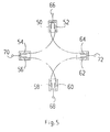
- FIGS. 1 and 2 show the circuit of the measuring elements, which generally designated 26 in FIGS. 1 and 2 are.
- Each measuring element 26 consists of a pair of parallel to each other and in substantially radially arranged strain gauges 50, 52; 54.56; 58.60 and 62.64.
- the strain gauges of each pair are each at a first end, outside in FIG. connected with each other.
- a second, inner, end of each DreismungsmeßstMails is with connected to the second end of a strain gauge of an adjacent pair, That is, the second end of the strain gauge 52 is connected to the second end of the Strain gauge strip 54 of the one, in Figure 5 left and horizontal, to the Strain gauges 50,52 vertical pair 54,56 connected; and the second end of the strain gauge 50 is connected to the strain gauge 64 of the other, in Fig.5 right and horizontal, to the strain gauges 50,52 vertical pair 62,64 connected.
- the second end of the strain gauge 56 of the pair 54,56 is connected to the second end of the strain gauge 60 of the pair 50,52 substantially aligned pair 58,60 connected.
- the second end of the strain gauge 58 of the Pair 58.60 is connected to the second end of the strain gauge 62 of the pair 62, 64 connected.
- the strain gauges 50, 52 and 58, 60 are perpendicular to those shown in FIG. attached diametrically opposite webs 18.
- the strain gauges 54,56 and 62,64 are horizontal on the in Fig.2, diametrically opposed attached to opposite webs 18.
- the strain gauges form one Bridge circuit.
- the bridge voltage between a terminal 66, the is connected between the first ends of the Drehnungsmeßst Shape 50,52, and a Clamp 68 is applied between the first ends of the strain gauges 58, 60 connected.
- a measuring signal is applied between a terminal 70 between the Strain gauge 54,56 is connected, and a terminal 72 tapped, the is connected between the strain gauges 62 and 64.
Landscapes
- Physics & Mathematics (AREA)
- General Physics & Mathematics (AREA)
- Engineering & Computer Science (AREA)
- Mechanical Engineering (AREA)
- Force Measurement Appropriate To Specific Purposes (AREA)
- Measurement Of The Respiration, Hearing Ability, Form, And Blood Characteristics Of Living Organisms (AREA)
- Details Of Spanners, Wrenches, And Screw Drivers And Accessories (AREA)
Abstract
Description
- Fig.1
- ist eine perspektivische Darstellung eines Drehmomentsensors zum Kalibrieren von Schraubwerkzeugen.
- Fig.2
- zeigt eine Vorderansicht einer zweiten Ausführung des Drehmomentsensors.
- Fig.3
- zeigt einen Schnitt längs der Linie A - A von Fig. 2.
- Fig.4
- ist eine perspektivische Darstellung, ähnlich Fig. 1, der zweiten Ausführung des Drehmomentsensors.
- Fig.5
- zeigt die Schaltung der Meßelemente.
Claims (8)
- Drehmomentsensor (10) enthaltend einen inneren Körper (12) mit einer Achse (19), in bezug auf welche ein Drehmoment zu messen ist, und einen äußeren Ringkörper (14), der den inneren Körper (12) konzentrisch umgibt und über radiale Stege (16,18) mit dem inneren Körper (12) verbunden ist, wobei eine erste Art von Stegen (18) mit in Umfangsrichtung relativ großer Breite aber relativ geringen axialen Abmessungen und eine zweite Art von in Umfangsrichtung relativ schmalen Stegen (16) aber relativ großen axialen Abmessungen vorgesehen sind, und Meßelemente (26) zur Torsionsmessung auf den Stegen (18) der ersten Art angeordnet sind,
dadurch gekennzeichnet, daß zum Kalibrieren von Schraubwerkzeugen,(a) der Ringkörper (14) stationär gehalten ist und(b) der innere Körper (12) eine zentrale, zu der Achse (19) koaxiale Aufnahme (20,21;40,42) zum Eingriff eines zu prüfendes Schraubwerkzeuges aufweist. - Drehmomentsensor nach Anspruch 1, dadurch gekennzeichnet, daß(a) der Ringkörper (14) durch ein erstes Kreuz von vier um jeweils 90° gegeneinander um die Achse winkelversetzten Stege (18) der ersten Art mit dem inneren Körper (12) verbunden ist,(b) der Ringkörper (14) weiterhin durch ein zweites Kreuz von vier um jeweils 90° um die Achse gegeneinander winkelversetzten Stegen (16) der zweiten Art mit dem inneren Körper (12) verbunden ist,(c) das zweite Kreuz um 45° um die Achse (19) gegen das erste Kreuz winkelversetzt ist,(d) Meßelemente (26) auf allen vier Stegen (18) der ersten Art angeordnet und so zusammengeschaltet sind, daß unter Kompensation von Störkräften ein Meßwert für ein um die Achse (19) auf den inneren Körper (12) wirke ndes Drehmoment erhalten wird.
- Drehmomentsensor nach Anspruch 1 oder 2, bei welchem das Trägheitsmoment des inneren Körpers (12) so klein ist, daß beim Kalibrieren von dynamisch arbeitenden Schraubwerkzeugen, wie Impulsschraubern, die von dem inneren Körper (12) hervorgerufenen Trägheitskräfte gegenüber den auf die Stege (18) wirkenden Kräften vernachlässigbar sind.
- Drehmomentsensor nach Anspruch 3, dadurch gekennzeichnet, daß die radialen Abmessungen des innere Körpers (12) klein gegen die radialen Abmessungen des Ringkörpers (14) sind.
- Drehmomentsensor nach Anspruch 3 oder 4, dadurch gekennzeichnet, daß der innere Körper (12) aus einem Material besteht, das ein gegenüber dem Material des Ringkörpers (14) geringes spezifisches Gewicht besitzt.
- Drehmomentsensor nach einem der Ansprüche 3 bis 5, dadurch gekennzeichnet, daß in dem inneren Körper (12) regelmäßig angeordnete Durchbrüche (22) zur Verminderung des Trägheitsmoments vorgesehen sind.
- Drehmomentsensor nach einem der Ansprüche 1 bis 6, dadurch gekennzeichnet, daß der innere Körper (12) als zentrale Aufnahme zum Eingriff eines zu prüfenden Schraubwerkzeugs eine Nabe (40) mit einem Vierkantdurchbruch (42) aufweist.
- Drehmomentsensor nach Anspruch 7, dadurch gekennzeichnet, daß der Vierkantdurchbruch (42) mit den Seitenflächen (44) des Vierkants zu den Stegen (18) der ersten Art und mit den Kanten (46) zu den Stegen (16) der zweiten Art ausgerichtet ist.
Applications Claiming Priority (2)
| Application Number | Priority Date | Filing Date | Title |
|---|---|---|---|
| DE20209850U DE20209850U1 (de) | 2002-06-25 | 2002-06-25 | Drehmomentsensor mit Stegen |
| DE20209850U | 2002-06-25 |
Publications (3)
| Publication Number | Publication Date |
|---|---|
| EP1376086A2 true EP1376086A2 (de) | 2004-01-02 |
| EP1376086A3 EP1376086A3 (de) | 2005-06-01 |
| EP1376086B1 EP1376086B1 (de) | 2010-12-29 |
Family
ID=7972528
Family Applications (1)
| Application Number | Title | Priority Date | Filing Date |
|---|---|---|---|
| EP03013818A Expired - Lifetime EP1376086B1 (de) | 2002-06-25 | 2003-06-18 | Drehmomentsensor |
Country Status (6)
| Country | Link |
|---|---|
| US (1) | US7093477B2 (de) |
| EP (1) | EP1376086B1 (de) |
| JP (1) | JP4397629B2 (de) |
| CN (1) | CN100425962C (de) |
| DE (2) | DE20209850U1 (de) |
| ES (1) | ES2358990T3 (de) |
Cited By (2)
| Publication number | Priority date | Publication date | Assignee | Title |
|---|---|---|---|---|
| WO2008090069A1 (fr) | 2007-01-18 | 2008-07-31 | Etablissements Georges Renault | Outil de vissage incluant un ou plusieurs capteurs de couple montes pour mesurer des deformations dans un plan perpendiculaire a un axe de revolution, et support de capteur correspondant |
| CN107690572A (zh) * | 2017-09-08 | 2018-02-13 | 深圳哥智行科技有限公司 | 中轴扭力光电传感器结构 |
Families Citing this family (55)
| Publication number | Priority date | Publication date | Assignee | Title |
|---|---|---|---|---|
| DE20210645U1 (de) | 2002-07-09 | 2002-09-12 | Eduard Wille GmbH & Co, 42349 Wuppertal | Prüfgerät mit integrierter Signalverarbeitung |
| WO2005075950A1 (ja) | 2004-02-04 | 2005-08-18 | Ono Sokki Co.,Ltd. | トルク計 |
| GB2436149B (en) * | 2006-03-15 | 2011-08-17 | Transense Technologies Plc | Torque measurement in flexible drive coupling plate |
| CN100348961C (zh) * | 2005-07-25 | 2007-11-14 | 浙江大学 | 无级升降式六维力传感器标定装置 |
| JP2007040774A (ja) * | 2005-08-02 | 2007-02-15 | Ono Sokki Co Ltd | トルク計 |
| DE102007005894A1 (de) * | 2006-06-14 | 2007-12-20 | GIF Gesellschaft für Industrieforschung mbH | Drehmomentmessflansch |
| DE202008002919U1 (de) * | 2008-02-29 | 2008-05-08 | Eduard Wille Gmbh & Co. Kg | Betätigungsvorrichtung zum Prüfen von Drehmomentschlüsseln |
| US9016398B2 (en) * | 2008-12-04 | 2015-04-28 | Ingersoll-Rand Company | Disc-shaped torque transducer |
| DE102009014284B4 (de) * | 2009-03-25 | 2017-01-26 | Hottinger Baldwin Messtechnik Gmbh | Drehmomentsensor |
| CN101893493B (zh) * | 2009-05-19 | 2013-05-08 | 鸿富锦精密工业(深圳)有限公司 | 扭力测试装置 |
| US8779306B2 (en) * | 2010-02-19 | 2014-07-15 | Methode Electronics, Inc. | Weight sensing method and apparatus for forklifts |
| DE202010005613U1 (de) * | 2010-06-10 | 2010-09-02 | Eduard Wille Gmbh & Co. Kg | Drehmoment-Aufnehmer mit U-Profil-Steg |
| US8381568B2 (en) * | 2010-09-03 | 2013-02-26 | Xiamen United Trade Electronic Co., Ltd. | Method of obtaining same wrench torque by calibration by testing different force exertion points on hand grip of electronic torque wrench and electronic torque wrench thereof |
| CN102865947A (zh) * | 2012-08-08 | 2013-01-09 | 燕山大学 | 容错式大量程并联六维力传感器 |
| CN103630292B (zh) * | 2013-11-29 | 2015-05-20 | 常州市计量测试技术研究所 | 一种自动施扭扭矩扳子检定仪 |
| DE102014017410A1 (de) | 2014-11-06 | 2016-05-12 | GIF Gesellschaft für Industrieforschung mbH | Drehmomentmesswelle |
| CN105181212B (zh) * | 2015-10-21 | 2017-12-19 | 重庆市银钢一通科技有限公司 | 一种链轮扭矩测量装置 |
| CN106197786B (zh) * | 2016-03-14 | 2018-12-07 | 山东大学 | 一种实时提取钻削扭矩信号的测试装置及方法 |
| JP2017172983A (ja) | 2016-03-18 | 2017-09-28 | 株式会社安川電機 | ロボット及びトルクセンサ |
| US10295418B1 (en) | 2016-03-29 | 2019-05-21 | X Development Llc | Factory-calibrated multi-spoke strain sensor system |
| DE102016010549A1 (de) | 2016-08-31 | 2018-03-01 | Sensodrive Gmbh | Drehmomentsensor mit Nebenschlussspeiche |
| DE202016008595U1 (de) * | 2016-10-17 | 2018-07-26 | Franka Emlka Gmbh | Drehmomentsensorvorrichtung zum Erfassen von Drehmomenten |
| WO2018124081A1 (ja) * | 2016-12-27 | 2018-07-05 | 第一精工株式会社 | トルクセンサ |
| JP6600824B2 (ja) * | 2017-02-16 | 2019-11-06 | 株式会社トライフォース・マネジメント | 力覚センサ |
| US11479059B2 (en) | 2017-10-30 | 2022-10-25 | Allan Hjorth Hansen | Gripping tool for adjustable wheel balancing clamping tools |
| WO2019163258A1 (ja) * | 2018-02-21 | 2019-08-29 | アルプスアルパイン株式会社 | トルクセンサ |
| JP6976892B2 (ja) * | 2018-03-29 | 2021-12-08 | 日本電産コパル電子株式会社 | トルクセンサ |
| JP7034811B2 (ja) * | 2018-04-09 | 2022-03-14 | 日本電産コパル電子株式会社 | 歪センサの固定装置とそれを用いたトルクセンサ |
| KR102072492B1 (ko) * | 2018-05-04 | 2020-02-04 | 주식회사 에이엘로봇 | 토크 센서 |
| JP6910990B2 (ja) * | 2018-07-02 | 2021-07-28 | 日本電産コパル電子株式会社 | トルクセンサの支持装置 |
| JP7091177B2 (ja) * | 2018-07-13 | 2022-06-27 | 日本電産コパル電子株式会社 | トルクセンサ |
| JP6999586B2 (ja) * | 2019-01-28 | 2022-01-18 | 日本電産コパル電子株式会社 | 弾性体とそれを用いた力覚センサ |
| US12508691B2 (en) | 2019-02-08 | 2025-12-30 | Allan HJORTH HANSEN | Self-releasing clamping tool |
| EP3693134B1 (de) * | 2019-02-08 | 2024-11-06 | Allan Hjorth Hansen | Greifwerkzeug für verstellbare radauswuchtspannwerkzeuge |
| DE202019101333U1 (de) * | 2019-03-08 | 2019-06-06 | SWEDEX GmbH Industrieprodukte | Drehmomentschrauberanordnung zum Betrieb einer solchen Drehmomentschrauberanordnung |
| DE102019207865A1 (de) * | 2019-05-29 | 2020-12-03 | Audi Ag | Wickelnadel, Wickelsystem für Drahtwicklungen und Verfahren zur Herstellung einer Drahtwicklung |
| CN110243518A (zh) * | 2019-06-17 | 2019-09-17 | 上海交通大学 | 轮辐式传感器构型 |
| JP6644307B2 (ja) * | 2019-08-23 | 2020-02-12 | 株式会社トライフォース・マネジメント | 力覚センサ |
| JP1667822S (de) * | 2019-11-29 | 2020-09-07 | ||
| JP1667823S (de) * | 2019-11-29 | 2020-09-07 | ||
| JP6685528B2 (ja) * | 2019-12-03 | 2020-04-22 | 株式会社トライフォース・マネジメント | 力覚センサ |
| CN111272379B (zh) * | 2020-02-05 | 2020-10-27 | 中国空气动力研究与发展中心低速空气动力研究所 | 一种微轴向力环形二分量应变天平 |
| USD1047642S1 (en) | 2020-02-07 | 2024-10-22 | Allan Hjorth Hansen | Adapter plate for self-releasing clamping tool |
| JP6710404B2 (ja) * | 2020-03-16 | 2020-06-17 | 株式会社トライフォース・マネジメント | 力覚センサ |
| JP6771797B2 (ja) * | 2020-04-10 | 2020-10-21 | 株式会社トライフォース・マネジメント | 力覚センサ |
| GB2597993B (en) * | 2020-08-14 | 2023-05-17 | Dyson Technology Ltd | Torque sensor element and torque sensor |
| CN112014023B (zh) * | 2020-08-31 | 2021-06-01 | 湖北文理学院 | 轮毂螺栓力矩检测装置 |
| JP6896309B2 (ja) * | 2020-09-18 | 2021-06-30 | 株式会社トライフォース・マネジメント | 力覚センサ |
| JP6784432B1 (ja) * | 2020-09-18 | 2020-11-11 | 株式会社トライフォース・マネジメント | 力覚センサ |
| JP6923991B2 (ja) * | 2020-10-16 | 2021-08-25 | 株式会社トライフォース・マネジメント | 力覚センサ |
| JP2022073177A (ja) * | 2020-10-30 | 2022-05-17 | 多摩川精機株式会社 | トルクセンサ、トルクセンサ製造方法、および耐荷重設計用トルクセンサ部品組 |
| JP7574120B2 (ja) * | 2021-03-22 | 2024-10-28 | ニデックコンポーネンツ株式会社 | トルクセンサ |
| CN113375859B (zh) * | 2021-06-30 | 2022-03-11 | 中国铁路郑州局集团有限公司科学技术研究所 | 一种可控扭矩冲击扳手在线校准方法及装置 |
| US11892364B2 (en) * | 2022-02-10 | 2024-02-06 | Ati Industrial Automation, Inc. | Torque sensor using coupled loads and fewer strain gages |
| JP7775123B2 (ja) * | 2022-03-25 | 2025-11-25 | ニデックコンポーネンツ株式会社 | トルクセンサ |
Family Cites Families (9)
| Publication number | Priority date | Publication date | Assignee | Title |
|---|---|---|---|---|
| US2403952A (en) * | 1944-09-02 | 1946-07-16 | Baldwin Locomotive Works | Torque meter |
| EP0117334A3 (de) * | 1982-11-09 | 1986-01-15 | EMI Limited | Für mehrere Kraftkomponenten empfindliche Vorrichtung |
| FR2563138B1 (fr) * | 1984-04-20 | 1986-08-08 | Framatome Sa | Dispositif pour l'etalonnage d'une machine-outil |
| US4759225A (en) * | 1987-06-01 | 1988-07-26 | Ryeson Corporation | Torque tool and torque tool analyzer |
| DE4012829C2 (de) * | 1990-04-23 | 1995-11-23 | Walter Rieger | Vorrichtung zur mehrdimensionalen Kraftmessung und daraus abgeleiteten Größen durch Meßwertaufnahme mittels elektrischer Sensoren, z. B. Dehnungsmeßstreifen |
| US5181425A (en) * | 1991-05-02 | 1993-01-26 | Ryeson Corporation | Apparatus and method for testing torque wrenches |
| US5672834A (en) * | 1994-01-29 | 1997-09-30 | British Autogard Limited | Torgue indicating device |
| FR2715729B1 (fr) * | 1994-01-29 | 1997-12-12 | British Autogard | Dispositif d'indication de couple. |
| FR2774469B1 (fr) * | 1998-02-04 | 2000-03-03 | Roulements Soc Nouvelle | Capteur de couple pour arbre tournant |
-
2002
- 2002-06-25 DE DE20209850U patent/DE20209850U1/de not_active Expired - Lifetime
-
2003
- 2003-06-18 ES ES03013818T patent/ES2358990T3/es not_active Expired - Lifetime
- 2003-06-18 DE DE50313358T patent/DE50313358D1/de not_active Expired - Lifetime
- 2003-06-18 EP EP03013818A patent/EP1376086B1/de not_active Expired - Lifetime
- 2003-06-23 US US10/602,097 patent/US7093477B2/en not_active Expired - Lifetime
- 2003-06-24 JP JP2003179586A patent/JP4397629B2/ja not_active Expired - Lifetime
- 2003-06-25 CN CNB031526934A patent/CN100425962C/zh not_active Expired - Lifetime
Cited By (4)
| Publication number | Priority date | Publication date | Assignee | Title |
|---|---|---|---|---|
| WO2008090069A1 (fr) | 2007-01-18 | 2008-07-31 | Etablissements Georges Renault | Outil de vissage incluant un ou plusieurs capteurs de couple montes pour mesurer des deformations dans un plan perpendiculaire a un axe de revolution, et support de capteur correspondant |
| CN107690572A (zh) * | 2017-09-08 | 2018-02-13 | 深圳哥智行科技有限公司 | 中轴扭力光电传感器结构 |
| WO2019047138A1 (zh) * | 2017-09-08 | 2019-03-14 | 深圳一哥智行科技有限公司 | 中轴扭力光电传感器结构 |
| CN107690572B (zh) * | 2017-09-08 | 2019-12-31 | 深圳一哥智行科技有限公司 | 中轴扭力光电传感器结构 |
Also Published As
| Publication number | Publication date |
|---|---|
| CN100425962C (zh) | 2008-10-15 |
| US20040003646A1 (en) | 2004-01-08 |
| EP1376086B1 (de) | 2010-12-29 |
| JP4397629B2 (ja) | 2010-01-13 |
| DE50313358D1 (de) | 2011-02-10 |
| JP2004029023A (ja) | 2004-01-29 |
| ES2358990T3 (es) | 2011-05-17 |
| DE20209850U1 (de) | 2002-09-19 |
| CN1480718A (zh) | 2004-03-10 |
| EP1376086A3 (de) | 2005-06-01 |
| US7093477B2 (en) | 2006-08-22 |
Similar Documents
| Publication | Publication Date | Title |
|---|---|---|
| EP1376086B1 (de) | Drehmomentsensor | |
| DE102009014284B4 (de) | Drehmomentsensor | |
| DE102016010551B3 (de) | Drehmomentsensor mit radialelastischer Momentübertragung | |
| DE3107925C2 (de) | Mechanisch/elektrischer Wandler mit sechs Freiheitsgraden | |
| EP2395335B1 (de) | Drehmoment-Aufnehmer mit U-Profil-Steg | |
| DE69922169T2 (de) | Drehmomentsensor für eine drehende welle | |
| EP3507581B1 (de) | Drehmomentsensor mit nebenschlussspeiche | |
| DE102016010552B3 (de) | Drehmomentsensor mit Dichtungsmembran | |
| AT508740B1 (de) | Drehmomentmesseinrichtung und anordnung aus einer drehmomentmesseinrichtung und einer triebwelle | |
| DE102005039855B4 (de) | Schraubenschlüssel mit Drehmomentanzeige | |
| WO2019144171A9 (de) | Messsystem und verfahren zur bestimmung einer kraft und/oder eines drehmoments an einer drehmomentübertragenden welle | |
| DE102012024264A1 (de) | Drehmomentsensor | |
| EP1353150A2 (de) | Drehwinkelmesseinrichtung | |
| DE19842231C1 (de) | Meßvorrichtung zur Bestimmung des Gesamtanzugsmoments, des Kopfreibungsmoments und der Vorspannkraft einer angezogenen Schraubverbindung | |
| EP3820649A1 (de) | Drehmomentschrauberanordnung und verfahren zum betrieb einer solchen drehmomentschrauberanordnung | |
| DE2945728A1 (de) | Axial verspannbarer kopfbolzen | |
| DE3737007A1 (de) | Verfahren und einrichtung zur drehmomentmessung | |
| EP0143434B1 (de) | Messnabe | |
| DE102004033925A1 (de) | Drehmoment-Messaufnehmer | |
| DE102016010546B3 (de) | Drehmomentsensor mit axialem Anschlagelement | |
| DE10055933A1 (de) | Aufnehmer zum Messen von Belastungen | |
| EP0482014A1 (de) | Messeinrichtung zur Bestimmung des Drehemoments | |
| DE10052069A1 (de) | Vorrichtung zum Messen von Drehmomenten in einer Antriebsanordnung | |
| EP0108894A1 (de) | Kapazitiver Drehmomentaufnehmer | |
| DE4419698C2 (de) | Vorrichtung zur Prüfung von Drehmomenten für Drehmomentschraubwerkzeuge |
Legal Events
| Date | Code | Title | Description |
|---|---|---|---|
| PUAI | Public reference made under article 153(3) epc to a published international application that has entered the european phase |
Free format text: ORIGINAL CODE: 0009012 |
|
| AK | Designated contracting states |
Kind code of ref document: A2 Designated state(s): AT BE BG CH CY CZ DE DK EE ES FI FR GB GR HU IE IT LI LU MC NL PT RO SE SI SK TR |
|
| AX | Request for extension of the european patent |
Extension state: AL LT LV MK |
|
| PUAL | Search report despatched |
Free format text: ORIGINAL CODE: 0009013 |
|
| AK | Designated contracting states |
Kind code of ref document: A3 Designated state(s): AT BE BG CH CY CZ DE DK EE ES FI FR GB GR HU IE IT LI LU MC NL PT RO SE SI SK TR |
|
| AX | Request for extension of the european patent |
Extension state: AL LT LV MK |
|
| 17P | Request for examination filed |
Effective date: 20051125 |
|
| AKX | Designation fees paid |
Designated state(s): DE ES FR GB IT SE |
|
| GRAP | Despatch of communication of intention to grant a patent |
Free format text: ORIGINAL CODE: EPIDOSNIGR1 |
|
| GRAS | Grant fee paid |
Free format text: ORIGINAL CODE: EPIDOSNIGR3 |
|
| GRAA | (expected) grant |
Free format text: ORIGINAL CODE: 0009210 |
|
| AK | Designated contracting states |
Kind code of ref document: B1 Designated state(s): DE ES FR GB IT SE |
|
| REG | Reference to a national code |
Ref country code: GB Ref legal event code: FG4D Free format text: NOT ENGLISH |
|
| REF | Corresponds to: |
Ref document number: 50313358 Country of ref document: DE Date of ref document: 20110210 Kind code of ref document: P |
|
| REG | Reference to a national code |
Ref country code: DE Ref legal event code: R096 Ref document number: 50313358 Country of ref document: DE Effective date: 20110210 |
|
| REG | Reference to a national code |
Ref country code: SE Ref legal event code: TRGR |
|
| REG | Reference to a national code |
Ref country code: ES Ref legal event code: FG2A Ref document number: 2358990 Country of ref document: ES Kind code of ref document: T3 Effective date: 20110517 |
|
| PLBE | No opposition filed within time limit |
Free format text: ORIGINAL CODE: 0009261 |
|
| STAA | Information on the status of an ep patent application or granted ep patent |
Free format text: STATUS: NO OPPOSITION FILED WITHIN TIME LIMIT |
|
| 26N | No opposition filed |
Effective date: 20110930 |
|
| REG | Reference to a national code |
Ref country code: DE Ref legal event code: R097 Ref document number: 50313358 Country of ref document: DE Effective date: 20110930 |
|
| REG | Reference to a national code |
Ref country code: DE Ref legal event code: R082 Ref document number: 50313358 Country of ref document: DE Representative=s name: WEISSE, JOERG, DIPL.-PHYS., DE Ref country code: DE Ref legal event code: R082 Ref document number: 50313358 Country of ref document: DE Representative=s name: PATENTANWAELTE WEISSE, MOLTMANN & WILLEMS PART, DE |
|
| REG | Reference to a national code |
Ref country code: FR Ref legal event code: PLFP Year of fee payment: 14 |
|
| REG | Reference to a national code |
Ref country code: DE Ref legal event code: R082 Ref document number: 50313358 Country of ref document: DE Representative=s name: PATENTANWAELTE WEISSE, MOLTMANN & WILLEMS PART, DE Ref country code: DE Ref legal event code: R081 Ref document number: 50313358 Country of ref document: DE Owner name: STAHLWILLE EDUARD WILLE GMBH & CO. KG, DE Free format text: FORMER OWNER: EDUARD WILLE GMBH & CO. KG, 42349 WUPPERTAL, DE |
|
| REG | Reference to a national code |
Ref country code: FR Ref legal event code: PLFP Year of fee payment: 15 |
|
| REG | Reference to a national code |
Ref country code: ES Ref legal event code: PC2A Owner name: STAHLWILLE EDUARD WILLE GMBH & CO. KG. Effective date: 20171030 |
|
| REG | Reference to a national code |
Ref country code: FR Ref legal event code: CD Owner name: STAHLWILLE EDUARD WILLE GMBH & CO. KG, DE Effective date: 20171215 |
|
| REG | Reference to a national code |
Ref country code: FR Ref legal event code: PLFP Year of fee payment: 16 |
|
| PGFP | Annual fee paid to national office [announced via postgrant information from national office to epo] |
Ref country code: IT Payment date: 20190626 Year of fee payment: 17 |
|
| PGFP | Annual fee paid to national office [announced via postgrant information from national office to epo] |
Ref country code: SE Payment date: 20190624 Year of fee payment: 17 |
|
| PGFP | Annual fee paid to national office [announced via postgrant information from national office to epo] |
Ref country code: ES Payment date: 20190723 Year of fee payment: 17 |
|
| PG25 | Lapsed in a contracting state [announced via postgrant information from national office to epo] |
Ref country code: SE Free format text: LAPSE BECAUSE OF NON-PAYMENT OF DUE FEES Effective date: 20200619 |
|
| REG | Reference to a national code |
Ref country code: SE Ref legal event code: EUG |
|
| PG25 | Lapsed in a contracting state [announced via postgrant information from national office to epo] |
Ref country code: IT Free format text: LAPSE BECAUSE OF NON-PAYMENT OF DUE FEES Effective date: 20200618 |
|
| REG | Reference to a national code |
Ref country code: ES Ref legal event code: FD2A Effective date: 20211029 |
|
| PG25 | Lapsed in a contracting state [announced via postgrant information from national office to epo] |
Ref country code: ES Free format text: LAPSE BECAUSE OF NON-PAYMENT OF DUE FEES Effective date: 20200619 |
|
| PGFP | Annual fee paid to national office [announced via postgrant information from national office to epo] |
Ref country code: GB Payment date: 20220624 Year of fee payment: 20 Ref country code: DE Payment date: 20220623 Year of fee payment: 20 |
|
| PGFP | Annual fee paid to national office [announced via postgrant information from national office to epo] |
Ref country code: FR Payment date: 20220623 Year of fee payment: 20 |
|
| REG | Reference to a national code |
Ref country code: DE Ref legal event code: R071 Ref document number: 50313358 Country of ref document: DE |
|
| REG | Reference to a national code |
Ref country code: GB Ref legal event code: PE20 Expiry date: 20230617 |
|
| PG25 | Lapsed in a contracting state [announced via postgrant information from national office to epo] |
Ref country code: GB Free format text: LAPSE BECAUSE OF EXPIRATION OF PROTECTION Effective date: 20230617 |