EP3693134B1 - Greifwerkzeug für verstellbare radauswuchtspannwerkzeuge - Google Patents
Greifwerkzeug für verstellbare radauswuchtspannwerkzeuge Download PDFInfo
- Publication number
- EP3693134B1 EP3693134B1 EP20156099.2A EP20156099A EP3693134B1 EP 3693134 B1 EP3693134 B1 EP 3693134B1 EP 20156099 A EP20156099 A EP 20156099A EP 3693134 B1 EP3693134 B1 EP 3693134B1
- Authority
- EP
- European Patent Office
- Prior art keywords
- annular body
- adjustable
- outer annular
- edge
- inner annular
- Prior art date
- Legal status (The legal status is an assumption and is not a legal conclusion. Google has not performed a legal analysis and makes no representation as to the accuracy of the status listed.)
- Active
Links
Images






Classifications
-
- B—PERFORMING OPERATIONS; TRANSPORTING
- B25—HAND TOOLS; PORTABLE POWER-DRIVEN TOOLS; MANIPULATORS
- B25B—TOOLS OR BENCH DEVICES NOT OTHERWISE PROVIDED FOR, FOR FASTENING, CONNECTING, DISENGAGING, OR HOLDING
- B25B5/00—Clamps
- B25B5/14—Clamps for work of special profile
-
- B—PERFORMING OPERATIONS; TRANSPORTING
- B60—VEHICLES IN GENERAL
- B60B—VEHICLE WHEELS; CASTORS; AXLES FOR WHEELS OR CASTORS; INCREASING WHEEL ADHESION
- B60B15/00—Wheels or wheel attachments designed for increasing traction
- B60B15/28—Wheel-ballasting weights; Their attachment
-
- B—PERFORMING OPERATIONS; TRANSPORTING
- B60—VEHICLES IN GENERAL
- B60B—VEHICLE WHEELS; CASTORS; AXLES FOR WHEELS OR CASTORS; INCREASING WHEEL ADHESION
- B60B3/00—Disc wheels, i.e. wheels with load-supporting disc body
- B60B3/14—Attaching disc body to hub ; Wheel adapters
Definitions
- the present invention relates generally to a grip system. More specifically, the present invention relates to a grip system for a wheel balancing clamping tool that can adjust to different bolt patterns.
- the wheel is flipped and the adjustable wheel balancing clamping tool is positioned against the back of the center bore wheel hub to correctly adjust the adjustable wheel balancing clamping tool according to the bolt pattern of the wheel. Then, the user uses one hand to mount the wheel on a wheel balancing machine, and the other hand to hold the adjustable wheel balancing clamping tool.
- An example of an existing adjustable wheel balancing clamping tool is D1 ( US20150069824 ) which discloses a wheel lug ring having an annular body with a cavity formed on one side having a plurality of lug wells in a registered positioning to engage around a plurality of lug nuts holding a wheel to an axle.
- the present invention addresses this issue by providing a gripping tool for the adjustable wheel balancing clamping tool according to claims 1 and 4.
- the present invention provides additional gripping surface area to the adjustable wheel balancing clamping tool that allows an individual to simultaneously adjust and hold the tool with one hand.
- the present invention provides the gripping tool for adjustable wheel balancing clamping tool, characterized in that the gripping tool comprises: a gripping body; an adjustable-bolt-pattern-adaptor attachment mechanism; the gripping body comprising an outer annular body, an inner annular body, and a connector ring; the inner annular body being concentrically positioned within the outer annular body; the connector ring being perimetrically connected the outer annular body and the inner annular body; a cross section between the outer annular body, the connector ring, and the inner annular body being a U-shaped cross section; the connector ring being terminally positioned to a first outer edge of the outer annular body and a first inner edge of the inner annular body; the adjustable-bolt-pattern-adaptor attachment mechanism being connected to the outer annular body and the inner annular body; the adjustable-bolt-pattern-adaptor attachment mechanism and the connector ring being oppositely oriented of each other about the outer annular body and the inner annular body; the adjustable-bolt-pattern-
- the present invention is a gripping tool for adjustable wheel balancing clamping tool so that the user is able to hold and adjust the adjustable wheel balancing clamping tool with only one hand. More specifically, the adjustable wheel balancing clamping tool enables the user to reliably mount a wheel on a wheel balancing machine in a desired orientation. To accomplish this, the adjustable wheel balancing clamping tool employs a stud adjustment system in order to change the orientation of the studs that engages with lug holes of the wheel. Generally, the user holds the adjustable wheel balancing clamping tool with one hand while the other hand is used to operate the stud adjustment system, which adjust the bolt pattern with respect to the wheel. However, the present invention functions as an accessory tool for the adjustable wheel balancing clamping tool so that the user can hold the adjustable wheel balancing clamping tool and operate the stud adjustment system with one hand.
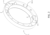
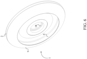
- the present invention comprises a gripping body 1 and an adjustable-bolt-pattern-adaptor attachment mechanism 10 as shown in FIG. 1-2 and 6-7.
- the gripping body 1 provides ergonomic surface area so that the user can comfortably grasp the present invention.
- the gripping body 1 comprises an outer annular body 2, an inner annular body 6, and a connector ring 9 thus delineating ring shaped body.
- the inner annular body 6 is concentrically positioned within the outer annular body 2.
- the connector ring 9 is perimetrically connected the outer annular body 2 and the inner annular body 6 as the structural body between the inner annular body 6 and the outer annular body 2.
- the connector ring 9 is terminally positioned to a first outer edge 3 of the outer annular body 2 and a first inner edge 7 of the inner annular body 6 so that the connector ring 9 can be positioned flush with the inner annular body 6 and the outer annular body 2.
- the user can use their fingers to apply upward tension to the inner annular body 6 thus pressing the connector ring 9 against the user's palm.
- the user can user their palm to apply tension to the connector ring 9 thus pressing the inner annular body 6 towards the user's fingers.
- the user can position their thumb over the outer annular body 2 to operate the stud adjustment system so that the bolt pattern of the adjustable wheel balancing clamping tool can be adjusted.
- the adjustable-bolt-pattern-adaptor attachment mechanism 10 is connected to the outer annular body 2 and the inner annular body 6 and functions as the attachment mechanism 10 that secures the present invention to the adjustable wheel balancing clamping tool. Furthermore, the adjustable-bolt-pattern-adaptor attachment mechanism 10 and the connector ring 9 are oppositely oriented of each other about the outer annular body 2 and the inner annular body 6 so that the stud adjustment system can be independently operated from the gripping body 1.
- the adjustable-bolt-pattern-adaptor attachment mechanism 10 preferably comprises a plurality of fasteners 11 that is radially positioned in between the outer annular body 2 and the inner annular body 6.
- the plurality of fasteners 11 functions as the attachment bodies for the gripping body 1 so that the present invention can be removably mounted to the adjustable wheel balancing clamping tool.
- the plurality of fasteners 11 each comprises a supporting rib 12, a female fastening portion 13, and a male fastening portion 14.
- the supporting rib 12 is generally a rectangular body and terminally connected to the outer annular body 2, the inner annular body 6, and the connector ring 9.
- the female fastening portion 13 is generally cylindrical body and connected to the supporting rib 12 and oriented away from the connector ring 9. In other words, the female fastening portion 13 is integrated into the supporting rib 12 so that an opening of the female fastening portion 13 is oriented in the opposite direction in comparison to the connector ring 9.
- the male fastening portion 14 is removably engaged with the female fastening portion 13 in such a way that the male fastening portion 14 and the female fastening portion 13 can collectively compress a base plate of the adjustable wheel balancing clamping tool.
- the male fastening portion 14 and the female fastening portion 13 are threadedly interconnected to each other so that the user is able to easily interact with the male fastening portion 14 with standard tooling apparatus such as screwdrivers, ratchet wrenches, and impact drivers.
- the male fastening portion 14 is designed to traverse through a cavity of the base plate so that the male fastening portion 14 can threadedly interconnect with the female fastening portion 13.
- the adjustable-bolt-pattern-adaptor attachment mechanism 10 further comprises a plurality of structural ribs 15 in addition to the plurality of fasteners 11.
- the plurality of structural ribs 15 is terminally connected to the outer annular body 2, the inner annular body 6, and the connector ring 9 to improve the structural integrity of the gripping body 1.
- each of the plurality of structural ribs 15 is radially spaced within the plurality of fasteners 11 to further structurally strengthen the each of the plurality of fasteners 11.
- the present invention can eliminate any structural misalignment as the female fastening portion 13 of each of the plurality of fasteners 11 can concentrically align with the cavities of the base plate to receive the male fastening portion 14.
- the outer annular body 2 further comprises a second outer edge 4 and a lip section 5, and the inner annular body 6 further comprises a second inner edge 8.
- the second outer edge 4 and the first outer edge 3 are oppositely positioned of each other about the outer annular body 2, wherein the second outer edge 4 is preferably a free hanging edge.
- the second inner edge 8 and the first inner edge 7 are oppositely positioned of each other about the inner annular body 6, wherein the second inner edge 8 is preferably a free hanging edge.
- the supporting rib 12 is positioned flush to the second inner edge 8 so that the second inner edge 8 and the plurality of fasteners 11 can position flat against the base plate.
- the lip section 5 is delineated from the supporting rib 12 to the second outer edge 4 so that the lip section 5 can perimetrically encircle around the base plate thus providing a precise alignment between the gripping body 1 and the base plate. Resultantly, the user can stationary grasp the adjustable wheel balancing clamping tool via the plurality of fasteners 11 and the gripping body 1 and adjust the bolt pattern with respect to the corresponding wheel by only utilizing one hand.
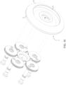
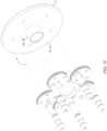
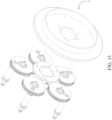
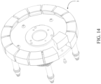
- the gripping body 1 and the adjustable-bolt-pattern-adaptor attachment mechanism 10 are preferably configured as a single apparatus, in alternative embodiments of the present invention, the gripping body 1 and the adjustable-bolt-pattern-adaptor attachment mechanism 10 can be made as a plurality of segmented pieces as shown in FIG. 14 .
- the outer annular body 2, the inner annular body 6, the connector ring 9, and the adjustable-bolt-pattern-adaptor attachment mechanism 10 can be manufactured as separate components and assembled together.
- the gripping body 1 and the adjustable-bolt-pattern-adaptor attachment mechanism 10 can also be segmented into a plurality of radial sections as the general profile of the gripping body 1 is collectively configured through the plurality of radial sections.
- the present invention can be alternatively integrated into the base plate of the adjustable wheel balancing clamping tool.
- the adjustable-bolt-pattern-adaptor attachment mechanism 10 may comprise a base plate 16, a plurality of pin-receiving recesses 17, and a central bushing 18.
- the functionality of the present invention and the base plate 16 are integrated to each other as the general profile of the gripping body 1 and the base plate 16 are constructed as a singular body. More specifically, the base plate 16 is radially connected to the outer annular body 2 and the inner annular body 6 thus enclosing the internal space between the outer annular body 2 and the inner annular body 6.
- the base plate 16 is terminally connected to the second outer edge 4 and the second inner edge 8 thus providing a structural base to configure the stud adjustment system around the central bushing 18.
- the central bushing 18 is concentrically connected to the base plate 16 so that the central bushing 18 can be mounted to the wheel balancing machine.
- the plurality of pin-receiving recesses 17 traverses into the base plate 16 and is distributed around the central bushing 18. More specifically, a first base surface 161 of the base plate 16 is radially connected onto the second inner edge 8 as the first base surface 161 extends from the inner annular body 6 to the central bushing 18.
- a second base surface 162 of the base plate 16 is positioned flush with the second outer edge 4 as the second base surface 162 extends from the second outer edge 4 to the central bushing 18. Resultantly, the user can stationarily grasp the adjustable wheel balancing clamping tool via the outer annular body 2 and the inner annular body 6 with respect to the first base surface 161 so that the bolt pattern can be adjusted via the stud adjustment system that is positioned adjacent to the second base surface 162 by only utilizing one hand.
- the present invention can be alternatively integrated into the base plate of the adjustable wheel balancing clamping tool thus defining an alternative embodiment.
- the base plate is radially connected to the outer annular body 2.
- the base plate is terminally connected to the second outer edge 4 thus providing a structural base to configure the stud adjustment system the central bushing.
- the central bushing is concentrically connected to the base plate so that the central bushing can be mounted to the wheel balancing machine.
- the present invention can be alternatively integrated into the base plate of the adjustable wheel balancing clamping tool thus defining another alternative embodiment. More specifically, the base plate is radially connected to the inner annular body 6. The base plate is terminally connected to the second inner edge 8 thus providing a structural base to configure the stud adjustment system the central bushing. The central bushing is concentrically connected to the base plate so that the central bushing can be mounted to the wheel balancing machine.
Landscapes
- Engineering & Computer Science (AREA)
- Mechanical Engineering (AREA)
- Manipulator (AREA)
- Constituent Portions Of Griding Lathes, Driving, Sensing And Control (AREA)
Claims (5)
- Greifwerkzeug für verstellbares Radauswuchtspannwerkzeug, wobei das Greifwerkzeug umfasst:einen Greifkörper (1);einen Anbringungsmechanismus (10) für einen verstellbaren Lochkreisadapter;wobei der Greifkörper (1) einen äußeren ringförmigen Körper (2), einen inneren ringförmigen Körper (6) und einen Verbinderring (9) umfasst;der innere ringförmige Körper (6) konzentrisch innerhalb des äußeren ringförmigen Körpers (2) positioniert ist;der Verbinderring (9) umkreisend mit dem äußeren ringförmigen Körper (2) und dem inneren ringförmigen Körper (6) verbunden ist;ein Querschnitt zwischen dem äußeren ringförmigen Körper (2), dem Verbinderring (9) und dem inneren ringförmigen Körper (6) ein U-förmiger Querschnitt ist;der Verbinderring (9) abschließend an einer ersten äußeren Kante (3) des äußeren ringförmigen Körpers (2) und einer ersten inneren Kante (7) des inneren ringförmigen Körpers (6) positioniert ist;der Anbringungsmechanismus (10) für einen verstellbaren Lochkreisadapter mit dem äußeren ringförmigen Körper (2) und dem inneren ringförmigen Körper (6) verbunden ist;der Anbringungsmechanismus (10) für einen verstellbaren Lochkreisadapter und der Verbinderring (9) entgegengesetzt zueinander um den äußeren ringförmigen Körper (2) und den inneren ringförmigen Körper (6) ausgerichtet sind;der Anbringungsmechanismus (10) für einen verstellbaren Lochkreisadapter eine Vielzahl von Befestigungselementen (11) umfasst;die Vielzahl von Befestigungselementen (11) jeweils eine Stützrippe (12), einen weiblichen Befestigungsteil (13) und einen männlichen Befestigungsteil (14) umfasst;der weibliche Befestigungsteil (13) sicher entlang der Stützrippe (12) befestigt ist;der weibliche Befestigungsteil (13) von dem äußeren ringförmigen Körper (2) versetzt positioniert ist;der weibliche Befestigungsteil (13) von dem inneren ringförmigen Körper (6) versetzt positioniert ist;der weibliche Befestigungsteil (13) von dem Verbinderring (9) weg ausgerichtet ist;der männliche Befestigungsteil (14) lösbar mit dem weiblichen Befestigungsteil (13) in Eingriff gebracht ist undder männliche Befestigungsteil (14) und der weibliche Befestigungsteil (13) durch ein Gewinde miteinander verbunden sind,dadurch gekennzeichnet, dass die Vielzahl von Befestigungselementen (26) radial zwischen dem äußeren ringförmigen Körper und dem inneren ringförmigen Körper positioniert istund dass die Stützrippe (14) abschließend mit dem äußeren ringförmigen Körper, dem inneren ringförmigen Körper (6) und dem Verbinderring (9) verbunden ist;und dass der weibliche Befestigungsteil (13) mit der Stützrippe (12) verbunden ist.
- Greifwerkzeug nach Anspruch 1, umfassend:der äußere ringförmige Körper (2) umfasst weiterhin eine zweite äußere Kante (4) undeinen Lippenabschnitt (5);der innere ringförmige Körper (6) umfasst weiterhin eine zweite innere Kante (8);die zweite äußere Kante (4) und die erste äußere Kante (3) sind entgegengesetzt zueinander um den äußeren ringförmigen Körper (2) positioniert;die zweite innere Kante (8) und die erste innere Kante (7) sind entgegengesetzt zueinander um den inneren ringförmigen Körper (6) positioniert;die Stützrippe (12) ist bündig mit der zweiten inneren Kante (8) positioniert undder Lippenabschnitt (5) ist von der Stützrippe (12) zu der zweiten äußeren Kante (4) abgegrenzt.
- Greifwerkzeug nach Anspruch 1, umfassend:der Anbringungsmechanismus (10) für einen verstellbaren Lochkreisadapter umfasst eine Vielzahl von Strukturrippen (15) unddie Vielzahl von Strukturrippen (15) ist abschließend mit dem äußeren ringförmigen Körper (2), dem inneren ringförmigen Körper (6) und dem Verbinderring (9) verbunden unddie Vielzahl von Strukturrippen (15) ist unter der Vielzahl von Befestigungselementen (11) radial eingestreut.
- Greifwerkzeug für verstellbares Radauswuchtspannwerkzeug, wobei das Greifwerkzeug umfasst:einen Greifkörper (1);einen Anbringungsmechanismus (10) für einen verstellbaren Lochkreisadapter;wobei der Greifkörper (1) einen äußeren ringförmigen Körper (2), einen inneren ringförmigen Körper (6) und einen Verbinderring (9) umfasst;der äußere ringförmige Körper (2) eine erste äußere Kante (3) und eine zweite äußere Kante (4) umfasst;der innere ringförmige Körper (6) eine erste innere Kante (7) und eine zweite innere Kante (8) umfasst;der innere ringförmige Körper (6) konzentrisch innerhalb des äußeren ringförmigen Körpers (2) positioniert ist;der Verbinderring (9) umkreisend mit dem äußeren ringförmigen Körper (2) und dem inneren ringförmigen Körper (6) verbunden ist;die erste äußere Kante (3) und die zweite äußere Kante (4) entgegengesetzt zueinander um den äußeren ringförmigen Körper (2) positioniert sind;die erste innere Kante (7) und die zweite innere Kante (8) entgegengesetzt zueinander um den inneren ringförmigen Körper (6) positioniert sind;der Verbinderring (9) abschließend an der ersten äußeren Kante (3) und der ersten inneren Kante (7) positioniert ist;der Anbringungsmechanismus (10) für einen verstellbaren Lochkreisadapter mit dem äußeren ringförmigen Körper (2) und dem inneren ringförmigen Körper (6) verbunden ist;der Anbringungsmechanismus (10) für einen verstellbaren Lochkreisadapter eine Basisplatte (16), eine Vielzahl von Stiftaufnahmeaussparungen (17) und eine zentrale Lagerbuchse (18) umfasst;die Basisplatte (16) radial mit dem äußeren ringförmigen Körper (2) und dem inneren ringförmigen Körper (6) verbunden ist;die Basisplatte (16) abschließend mit der zweiten äußeren Kante (4) und der zweiten inneren Kante (8) verbunden ist;die zentrale Lagerbuchse (18) konzentrisch mit der Basisplatte verbunden ist;dadurch gekennzeichnet, dass der Anbringungsmechanismus für einen verstellbaren Lochkreisadapter und der Verbinderring (9) entgegengesetzt zueinander um den äußeren ringförmigen Körper (2) und den inneren ringförmigen Körper (6) ausgerichtet sind und dasseine vorragende Form, die zwischen dem äußeren ringförmigen Körper (2), dem Verbinderring (9) und dem inneren ringförmigen Körper (6) abgegrenzt ist, in einer entgegengesetzten Richtung zu der zentralen Lagerbuchse (18) ausgerichtet ist;die Vielzahl von Stiftaufnahmeaussparungen (17) in die Basisplatte (16) verläuft;die Vielzahl von Stiftaufnahmeaussparungen (17) versetzt von der vorragenden Form, die zwischen dem äußeren ringförmigen Körper (2), dem Verbinderring (9) und dem inneren ringförmigen Körper (6) abgegrenzt ist, abgewinkelt positioniert ist;die Vielzahl von Stiftaufnahmeaussparungen (17) angrenzend an die zentrale Lagerbuchse (18) abgewinkelt positioniert ist unddie Vielzahl von Stiftaufnahmeaussparungen (17) um die zentrale Lagerbuchse (18) verteilt ist.
- Greifwerkzeug für verstellbares Radauswuchtspannwerkzeug nach Anspruch 4, umfassend:die Basisplatte (16) umfasst eine erste Basisfläche (161) und eine zweite Basisfläche (162);die erste Basisfläche (161) ist radial auf der zweiten inneren Kante (8) verbunden;die erste Basisfläche (161) erstreckt sich von dem äußeren ringförmigen Körper (2) zu der zentralen Lagerbuchse (18);die zweite Basisfläche (162) ist bündig mit der zweiten inneren Kante (4) positioniert;die zweite Basisfläche (162) erstreckt sich von der zweiten äußeren Kante (3) zu der zentralen Lagerbuchse (18);jede von der Vielzahl von Stiftaufnahmeaussparungen (17) verläuft in die Basisplatte (16) von der ersten Basisfläche (161) undjede von der Vielzahl von Stiftaufnahmeaussparungen (17) ist versetzt von der zweiten Basisfläche (162) positioniert.
Applications Claiming Priority (1)
| Application Number | Priority Date | Filing Date | Title |
|---|---|---|---|
| US201962803171P | 2019-02-08 | 2019-02-08 |
Publications (3)
| Publication Number | Publication Date |
|---|---|
| EP3693134A1 EP3693134A1 (de) | 2020-08-12 |
| EP3693134B1 true EP3693134B1 (de) | 2024-11-06 |
| EP3693134C0 EP3693134C0 (de) | 2024-11-06 |
Family
ID=69528568
Family Applications (1)
| Application Number | Title | Priority Date | Filing Date |
|---|---|---|---|
| EP20156099.2A Active EP3693134B1 (de) | 2019-02-08 | 2020-02-07 | Greifwerkzeug für verstellbare radauswuchtspannwerkzeuge |
Country Status (1)
| Country | Link |
|---|---|
| EP (1) | EP3693134B1 (de) |
Citations (1)
| Publication number | Priority date | Publication date | Assignee | Title |
|---|---|---|---|---|
| US3143327A (en) * | 1962-05-30 | 1964-08-04 | Replex Proprietary Ltd | Adapter units for wheel balancing apparatus |
Family Cites Families (5)
| Publication number | Priority date | Publication date | Assignee | Title |
|---|---|---|---|---|
| GB170283A (en) * | 1920-10-12 | 1922-07-06 | Carl Schenck Eisengiesserei Un | Methods and devices for balancing rotating bodies and automatically setting the counterbalancing masses into the plane of the unbalancing force |
| US4885962A (en) * | 1989-02-06 | 1989-12-12 | Summers Ronald L | Pneumatic torque wrench for valve handwheels |
| DE20209850U1 (de) * | 2002-06-25 | 2002-09-19 | Eduard Wille GmbH & Co, 42349 Wuppertal | Drehmomentsensor mit Stegen |
| US9272569B2 (en) * | 2011-03-29 | 2016-03-01 | Craig McClain Matsler | Wheel lug ring |
| GB2513905B (en) * | 2013-05-10 | 2020-05-20 | Universal Balancing Ltd | Apparatus for driving a rotor |
-
2020
- 2020-02-07 EP EP20156099.2A patent/EP3693134B1/de active Active
Patent Citations (1)
| Publication number | Priority date | Publication date | Assignee | Title |
|---|---|---|---|---|
| US3143327A (en) * | 1962-05-30 | 1964-08-04 | Replex Proprietary Ltd | Adapter units for wheel balancing apparatus |
Also Published As
| Publication number | Publication date |
|---|---|
| EP3693134C0 (de) | 2024-11-06 |
| EP3693134A1 (de) | 2020-08-12 |
Similar Documents
| Publication | Publication Date | Title |
|---|---|---|
| US9933109B2 (en) | Vibration resistant equipment mount | |
| US7047847B2 (en) | Toolkit with chain tool | |
| EP1537957B1 (de) | Werkzeughalter mit Teil zum Anzeigen der Werkzeugspezifikation | |
| US6626502B1 (en) | Wheel adaptor plate system | |
| US5446967A (en) | Mounting apparatus | |
| US11479059B2 (en) | Gripping tool for adjustable wheel balancing clamping tools | |
| US11858109B2 (en) | Side handle for an electric hand-held power tool | |
| US5074174A (en) | Socket wrench | |
| EP3693134B1 (de) | Greifwerkzeug für verstellbare radauswuchtspannwerkzeuge | |
| EP2556972B1 (de) | Reifenwulstabklemmwerkzeug und Herstellungsverfahren dafür | |
| EP1516808B1 (de) | Motorrad mit Zubehör | |
| US12508691B2 (en) | Self-releasing clamping tool | |
| US20210031333A1 (en) | Clamp assembly | |
| EP3202535B1 (de) | Handratschenwerkzeug | |
| US11173624B2 (en) | Router base having adjustable mounting slots | |
| CN114227600A (zh) | 一种可灵活转位舱段装配工装及使用方法 | |
| US20150000478A1 (en) | C-type pliers | |
| US20050034586A1 (en) | Adjustable drill bushing alignment device | |
| TWI629139B (zh) | 活動扳手 | |
| GB2381563A (en) | Holding device of belt wheel structure | |
| USD929312S1 (en) | Tire | |
| CN209903137U (zh) | 一种钳工台旋转装置的锁紧机构 | |
| CN207616427U (zh) | 镊子 | |
| EP3974213B1 (de) | Backe, radhaltereinheit und reifenwechselvorrichtung | |
| CN218449656U (zh) | 一种可调节的电机 |
Legal Events
| Date | Code | Title | Description |
|---|---|---|---|
| PUAI | Public reference made under article 153(3) epc to a published international application that has entered the european phase |
Free format text: ORIGINAL CODE: 0009012 |
|
| STAA | Information on the status of an ep patent application or granted ep patent |
Free format text: STATUS: THE APPLICATION HAS BEEN PUBLISHED |
|
| AK | Designated contracting states |
Kind code of ref document: A1 Designated state(s): AL AT BE BG CH CY CZ DE DK EE ES FI FR GB GR HR HU IE IS IT LI LT LU LV MC MK MT NL NO PL PT RO RS SE SI SK SM TR |
|
| AX | Request for extension of the european patent |
Extension state: BA ME |
|
| STAA | Information on the status of an ep patent application or granted ep patent |
Free format text: STATUS: REQUEST FOR EXAMINATION WAS MADE |
|
| 17P | Request for examination filed |
Effective date: 20210128 |
|
| RBV | Designated contracting states (corrected) |
Designated state(s): AL AT BE BG CH CY CZ DE DK EE ES FI FR GB GR HR HU IE IS IT LI LT LU LV MC MK MT NL NO PL PT RO RS SE SI SK SM TR |
|
| STAA | Information on the status of an ep patent application or granted ep patent |
Free format text: STATUS: EXAMINATION IS IN PROGRESS |
|
| 17Q | First examination report despatched |
Effective date: 20220317 |
|
| GRAP | Despatch of communication of intention to grant a patent |
Free format text: ORIGINAL CODE: EPIDOSNIGR1 |
|
| STAA | Information on the status of an ep patent application or granted ep patent |
Free format text: STATUS: GRANT OF PATENT IS INTENDED |
|
| INTG | Intention to grant announced |
Effective date: 20240527 |
|
| GRAS | Grant fee paid |
Free format text: ORIGINAL CODE: EPIDOSNIGR3 |
|
| GRAA | (expected) grant |
Free format text: ORIGINAL CODE: 0009210 |
|
| STAA | Information on the status of an ep patent application or granted ep patent |
Free format text: STATUS: THE PATENT HAS BEEN GRANTED |
|
| AK | Designated contracting states |
Kind code of ref document: B1 Designated state(s): AL AT BE BG CH CY CZ DE DK EE ES FI FR GB GR HR HU IE IS IT LI LT LU LV MC MK MT NL NO PL PT RO RS SE SI SK SM TR |
|
| REG | Reference to a national code |
Ref country code: GB Ref legal event code: FG4D |
|
| REG | Reference to a national code |
Ref country code: CH Ref legal event code: EP |
|
| REG | Reference to a national code |
Ref country code: DE Ref legal event code: R096 Ref document number: 602020040642 Country of ref document: DE |
|
| REG | Reference to a national code |
Ref country code: IE Ref legal event code: FG4D |
|
| U01 | Request for unitary effect filed |
Effective date: 20241206 |
|
| U07 | Unitary effect registered |
Designated state(s): AT BE BG DE DK EE FI FR IT LT LU LV MT NL PT RO SE SI Effective date: 20241216 |
|
| U20 | Renewal fee for the european patent with unitary effect paid |
Year of fee payment: 6 Effective date: 20250206 |
|
| PG25 | Lapsed in a contracting state [announced via postgrant information from national office to epo] |
Ref country code: HR Free format text: LAPSE BECAUSE OF FAILURE TO SUBMIT A TRANSLATION OF THE DESCRIPTION OR TO PAY THE FEE WITHIN THE PRESCRIBED TIME-LIMIT Effective date: 20241106 Ref country code: IS Free format text: LAPSE BECAUSE OF FAILURE TO SUBMIT A TRANSLATION OF THE DESCRIPTION OR TO PAY THE FEE WITHIN THE PRESCRIBED TIME-LIMIT Effective date: 20250306 |
|
| PG25 | Lapsed in a contracting state [announced via postgrant information from national office to epo] |
Ref country code: ES Free format text: LAPSE BECAUSE OF FAILURE TO SUBMIT A TRANSLATION OF THE DESCRIPTION OR TO PAY THE FEE WITHIN THE PRESCRIBED TIME-LIMIT Effective date: 20241106 |
|
| PG25 | Lapsed in a contracting state [announced via postgrant information from national office to epo] |
Ref country code: NO Free format text: LAPSE BECAUSE OF FAILURE TO SUBMIT A TRANSLATION OF THE DESCRIPTION OR TO PAY THE FEE WITHIN THE PRESCRIBED TIME-LIMIT Effective date: 20250206 |
|
| PG25 | Lapsed in a contracting state [announced via postgrant information from national office to epo] |
Ref country code: GR Free format text: LAPSE BECAUSE OF FAILURE TO SUBMIT A TRANSLATION OF THE DESCRIPTION OR TO PAY THE FEE WITHIN THE PRESCRIBED TIME-LIMIT Effective date: 20250207 |
|
| PG25 | Lapsed in a contracting state [announced via postgrant information from national office to epo] |
Ref country code: PL Free format text: LAPSE BECAUSE OF FAILURE TO SUBMIT A TRANSLATION OF THE DESCRIPTION OR TO PAY THE FEE WITHIN THE PRESCRIBED TIME-LIMIT Effective date: 20241106 |
|
| PG25 | Lapsed in a contracting state [announced via postgrant information from national office to epo] |
Ref country code: RS Free format text: LAPSE BECAUSE OF FAILURE TO SUBMIT A TRANSLATION OF THE DESCRIPTION OR TO PAY THE FEE WITHIN THE PRESCRIBED TIME-LIMIT Effective date: 20250206 |
|
| PG25 | Lapsed in a contracting state [announced via postgrant information from national office to epo] |
Ref country code: SM Free format text: LAPSE BECAUSE OF FAILURE TO SUBMIT A TRANSLATION OF THE DESCRIPTION OR TO PAY THE FEE WITHIN THE PRESCRIBED TIME-LIMIT Effective date: 20241106 |
|
| PG25 | Lapsed in a contracting state [announced via postgrant information from national office to epo] |
Ref country code: SK Free format text: LAPSE BECAUSE OF FAILURE TO SUBMIT A TRANSLATION OF THE DESCRIPTION OR TO PAY THE FEE WITHIN THE PRESCRIBED TIME-LIMIT Effective date: 20241106 |
|
| PG25 | Lapsed in a contracting state [announced via postgrant information from national office to epo] |
Ref country code: CZ Free format text: LAPSE BECAUSE OF FAILURE TO SUBMIT A TRANSLATION OF THE DESCRIPTION OR TO PAY THE FEE WITHIN THE PRESCRIBED TIME-LIMIT Effective date: 20241106 |
|
| PLBE | No opposition filed within time limit |
Free format text: ORIGINAL CODE: 0009261 |
|
| STAA | Information on the status of an ep patent application or granted ep patent |
Free format text: STATUS: NO OPPOSITION FILED WITHIN TIME LIMIT |
|
| PG25 | Lapsed in a contracting state [announced via postgrant information from national office to epo] |
Ref country code: MC Free format text: LAPSE BECAUSE OF FAILURE TO SUBMIT A TRANSLATION OF THE DESCRIPTION OR TO PAY THE FEE WITHIN THE PRESCRIBED TIME-LIMIT Effective date: 20241106 |
|
| REG | Reference to a national code |
Ref country code: CH Ref legal event code: PL |
|
| 26N | No opposition filed |
Effective date: 20250807 |
|
| PG25 | Lapsed in a contracting state [announced via postgrant information from national office to epo] |
Ref country code: CH Free format text: LAPSE BECAUSE OF NON-PAYMENT OF DUE FEES Effective date: 20250228 |
|
| GBPC | Gb: european patent ceased through non-payment of renewal fee |
Effective date: 20250207 |
|
| PG25 | Lapsed in a contracting state [announced via postgrant information from national office to epo] |
Ref country code: GB Free format text: LAPSE BECAUSE OF NON-PAYMENT OF DUE FEES Effective date: 20250207 |
|
| PG25 | Lapsed in a contracting state [announced via postgrant information from national office to epo] |
Ref country code: IE Free format text: LAPSE BECAUSE OF NON-PAYMENT OF DUE FEES Effective date: 20250207 |
|
| U20 | Renewal fee for the european patent with unitary effect paid |
Year of fee payment: 7 Effective date: 20260206 |