EP1375989B1 - Piezoelektrisches Ventil - Google Patents
Piezoelektrisches Ventil Download PDFInfo
- Publication number
- EP1375989B1 EP1375989B1 EP20030450134 EP03450134A EP1375989B1 EP 1375989 B1 EP1375989 B1 EP 1375989B1 EP 20030450134 EP20030450134 EP 20030450134 EP 03450134 A EP03450134 A EP 03450134A EP 1375989 B1 EP1375989 B1 EP 1375989B1
- Authority
- EP
- European Patent Office
- Prior art keywords
- valve
- bending transducer
- sealing element
- valve according
- sealing
- Prior art date
- Legal status (The legal status is an assumption and is not a legal conclusion. Google has not performed a legal analysis and makes no representation as to the accuracy of the status listed.)
- Expired - Lifetime
Links
- 238000005452 bending Methods 0.000 claims description 67
- 238000007789 sealing Methods 0.000 claims description 64
- 238000006073 displacement reaction Methods 0.000 claims 3
- 230000006835 compression Effects 0.000 description 8
- 238000007906 compression Methods 0.000 description 8
- 238000010276 construction Methods 0.000 description 3
- 230000000284 resting effect Effects 0.000 description 2
- 230000003746 surface roughness Effects 0.000 description 2
- 230000002411 adverse Effects 0.000 description 1
- 230000033228 biological regulation Effects 0.000 description 1
- 230000007423 decrease Effects 0.000 description 1
- 230000003247 decreasing effect Effects 0.000 description 1
- 230000005283 ground state Effects 0.000 description 1
- 239000002184 metal Substances 0.000 description 1
- 238000004377 microelectronic Methods 0.000 description 1
- 230000007935 neutral effect Effects 0.000 description 1
- 230000036316 preload Effects 0.000 description 1
- 230000001105 regulatory effect Effects 0.000 description 1
Images


Classifications
-
- F—MECHANICAL ENGINEERING; LIGHTING; HEATING; WEAPONS; BLASTING
- F16—ENGINEERING ELEMENTS AND UNITS; GENERAL MEASURES FOR PRODUCING AND MAINTAINING EFFECTIVE FUNCTIONING OF MACHINES OR INSTALLATIONS; THERMAL INSULATION IN GENERAL
- F16K—VALVES; TAPS; COCKS; ACTUATING-FLOATS; DEVICES FOR VENTING OR AERATING
- F16K31/00—Actuating devices; Operating means; Releasing devices
- F16K31/004—Actuating devices; Operating means; Releasing devices actuated by piezoelectric means
- F16K31/005—Piezoelectric benders
- F16K31/006—Piezoelectric benders having a free end
-
- Y—GENERAL TAGGING OF NEW TECHNOLOGICAL DEVELOPMENTS; GENERAL TAGGING OF CROSS-SECTIONAL TECHNOLOGIES SPANNING OVER SEVERAL SECTIONS OF THE IPC; TECHNICAL SUBJECTS COVERED BY FORMER USPC CROSS-REFERENCE ART COLLECTIONS [XRACs] AND DIGESTS
- Y10—TECHNICAL SUBJECTS COVERED BY FORMER USPC
- Y10T—TECHNICAL SUBJECTS COVERED BY FORMER US CLASSIFICATION
- Y10T137/00—Fluid handling
- Y10T137/8593—Systems
- Y10T137/86493—Multi-way valve unit
- Y10T137/86847—Pivoted valve unit
-
- Y—GENERAL TAGGING OF NEW TECHNOLOGICAL DEVELOPMENTS; GENERAL TAGGING OF CROSS-SECTIONAL TECHNOLOGIES SPANNING OVER SEVERAL SECTIONS OF THE IPC; TECHNICAL SUBJECTS COVERED BY FORMER USPC CROSS-REFERENCE ART COLLECTIONS [XRACs] AND DIGESTS
- Y10—TECHNICAL SUBJECTS COVERED BY FORMER USPC
- Y10T—TECHNICAL SUBJECTS COVERED BY FORMER US CLASSIFICATION
- Y10T137/00—Fluid handling
- Y10T137/8593—Systems
- Y10T137/87169—Supply and exhaust
- Y10T137/87217—Motor
-
- Y—GENERAL TAGGING OF NEW TECHNOLOGICAL DEVELOPMENTS; GENERAL TAGGING OF CROSS-SECTIONAL TECHNOLOGIES SPANNING OVER SEVERAL SECTIONS OF THE IPC; TECHNICAL SUBJECTS COVERED BY FORMER USPC CROSS-REFERENCE ART COLLECTIONS [XRACs] AND DIGESTS
- Y10—TECHNICAL SUBJECTS COVERED BY FORMER USPC
- Y10T—TECHNICAL SUBJECTS COVERED BY FORMER US CLASSIFICATION
- Y10T137/00—Fluid handling
- Y10T137/8593—Systems
- Y10T137/877—With flow control means for branched passages
- Y10T137/87708—With common valve operator
- Y10T137/87772—With electrical actuation
Definitions
- the invention relates to a valve with a deflectable actuator, which the movements of at least one actual sealing element for opening or closing controls, wherein the actuating element by an elastic element substantially perpendicular is applied to the deflection, wherein the longitudinal axis of the actuating element and the force exerted by the elastic member in a position of the operating member between its two extreme positions are aligned, or a valve with a deflectable Actuator, which controls the movements of at least one actual Sealing element for opening or closing controls, wherein an elastic element substantially perpendicular to the deflection of the actuating element acts and the longitudinal axis of the actuating element and the force exerted by the elastic element in the force essentially aligned.
- the sealing element or a this sealing element is moving Actuator in one of the two directions by means of, for example, elastic Elements preloaded.
- the bias may also be caused by the forces be formed when the deflection of the sealing or actuating element.
- this also the switching dynamics of the valve at least in one direction adversely affected and much power consumption of the valve is used for overcoming this Preload needed.
- valve constructions are known in which by the geometry the sealing or actuating element - at best, with the help of at least one Spring element - the two end positions are held stable by bias while to switch over the force of an elastic element must be overcome, wherein after passing through a first section of the entire working stroke, the elastic element supports further switching.
- An example of such a valve is in the DE 197 20 849 A1 described, where two actuators are provided for switching, which on the Carrier element for the actual sealing element act.
- the object of the invention is an electrically switchable valve with low currents, which is particularly characterized by small size, but still large travel paths can be realized.
- the invention provides that the actuating element is designed as a cantilevered piezoelectric bending transducer.
- This on known flexural transducers offer very high through their low drive power Power-tight and good switching dynamics all the prerequisites for a long stroke with the lowest Dimensions.
- the elastic element which exerts its greatest force in the neutral position of the bending transducer and with increasing deflection and thus decreasing deflection force of the bending transducer also exerts less force, the full idle stroke of the bending transducer can be used and The achievable stroke - which is accompanied by an increase in the flow rate of valves again goes - be substantially enlarged.
- At least one of the actual sealing elements on the bending transducer mounted or integrated therein.
- the actuating element as a cantilevered piezoelectric bending transducer is executed, and the sealing element by an elastic element substantially is acted upon perpendicular to the deflection of the actuating element.
- the bending transducer can be operated with its full deflection and over the geometric Conditions can the sealing force, the working stroke of the sealing element and the like. At the requirements are adapted in practice.
- the sealing element is mounted pivotably about an axis, the is preferably arranged laterally next to the valve seat.
- the exercisable by the bending transducer force can be brought to the best advantage be when the point of the bending transducer on the sealing element outside of the axis and the valve seat defined level lies.
- the restoring force of the bending transducer can be optimally used for switching the valve are, if according to a further feature of the invention, the sealing element a Recess, in which engages one end of the bending transducer.
- valve construction according to the invention can also be ensured by an embodiment in which two sealing elements provided which are independent of one another in opposite directions Axis are pivotally mounted, which axis each disposed laterally adjacent to the valve seat is.
- each Sealing element with two valve seats on each other with respect to its pivot axis opposite Side cooperates, each sealing element preferably by the elastic element is biased on one of the two valve seats and by the bending transducer can be switched between the two switch positions.
- the restoring forces of both deflection positions of the bending transducer be used when the two sealing elements in the ground state with each other Forming on the bending transducer open recess, in which one end of the bending transducer intervenes.
- the applicability and versatility of the valve can be further increased in in which a pressure sensor is integrated into the valve.
- control electronics driving the bending transducer integrated into the valve and also be connected to the pressure sensor.
- control electronics with an external input is equipped for a setpoint signal.
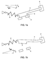
- Fig. 1a shows a schematic representation of a piezoelectric bending transducer for a valve according to the invention in cooperation with a compression spring and the valve seat in the closed position and Fig. 1b shows this bending transducer in the open position
- the Fig. 2 is a schematic representation of a bending transducer for the second invention Valve variant with pivotable sealing element in the closed position
- Fig. 3 is a perspective view of a 3/3-way valve according to the second valve variant with two sealing elements with bending transducer as a common actuator.
- a piezoelectric bending transducer 1 is at one end in a clamping 2 in Housing of the valve or an associated structure held. In that shown in Fig. 1a Resting position, in which no voltage is applied, presses the bending transducer 1 Sealing element 3 on the valve seat 4.
- the closing force is due to the mechanical properties the bending transducer 1 and additionally given by the action of the compression spring 5, the is arranged substantially flush with the bending transducer 1, or only a blunt Angle near 180 ° with this includes, whose larger force component so substantially in the longitudinal direction of the bending transducer 1 and thus substantially perpendicular to its Deflection direction acts.
- the force in the rest position is by acting in Auslenkrich ung Proportion Fb of the spring force Fges determined.
- the bending transducer 1 Upon application of a voltage, the bending transducer 1 in finally the in Fig. 1b deflected end position shown, in the course of this movement in the direction of deflection acting spring force Fb decreases until it disappears completely when compression spring 5 and Bending transducer 1 are aligned completely aligned in an intermediate position.
- the compression spring 5 again an obtuse angle close to 180 ° with the bending transducer 1, but with respect to the opposite side with respect points to the position of Fig. 1a, then supports the now acting in the direction of deflection Federkraftanteil Fb the further deflection of the bending transducer 1 in the open end position.
- the maximum deflection position is symmetrical to the rest position, so that when Turning off the tension of the bending transducer 1 by its elasticity sufficient restoring force has, in the direction of deflection and in the opening direction acting spring component Fb to overcome.
- the bending transducer acts to a separate sealing element 6, which is a lying mostly next to the valve seat 4 Axis 7 is pivotable. At the sealing element 6, the actual sealing surface 3 is worked out or attached.
- the compression spring 5 does not act directly on the in this embodiment Bending transducer 1, but acts, lying substantially parallel to the bending transducer 1, in Direction to the valve seat 4 on the sealing element 6 a. Due to the low angle, the compression spring 5 includes with the bending transducer 1, in turn, a small proportion the spring force as spring force Fb in the deflection of the bending transducer 1 and acts Deflection against applied voltage.
- the closing force Fa which is substantially the force Fges of the compression spring 5 and the perpendicular to the Biegewandlerausschung acting proportion of Spring force corresponds to Fges, decoupled, so they are also designed to be much higher can than conventional systems and also in the variant first described above.
- the valve can either in a higher pressure range work or by increasing the diameter of the valve seat 4, the Flow can be significantly increased.
- the friction in the pivot bearings 7 of the sealing element 6 and at the points of attack the compression spring 5, which - as shown in Fig. 3 - be formed as a sheet metal bent part can, at the sealing element 6 can by training these pivot bearing 7 and attack points on Sealing element 6 can be reduced as cutting edges.
- the friction between bending transducer 1 and sealing element 6 can also be about cutting edges 9 or by otherwise minimization the surface roughness of at least one of the components 1, 6, preferably both components, be reduced. This can, for example, by pushing a cap with minimal surface roughness on the bending transducer 1 done.
- valves of both variants are in their simplest embodiment with a Valve seat 4 and thus shown as 2/2-way valves.
- a further valve seat in the latter case preferably in a order 90 ° relative to the first valve seat 4 rotated plane, substantially parallel to the bending transducer 1.
- a piezoelectric bending transducer 1 is also a 3/3-way valve to realize, with a preferred embodiment in Fig. 3 is shown. It will be there a held in a chuck 2 in the housing bending transducer 1 used to his Resting position can be deflected in both directions, for example by applying of tension with different signs. For example, after deflection on the right in Fig.
- the bag 8 in Sealing element 6a is effective only in the deflected position, while a movement of the Bending transducer 1 in the opposite direction of the above deflection not may hamper.
- the second sealing element 6b remains, acted upon by the spring 5b, in Closed position.
- the two sealing elements 6a, 6b form in their closed position with each other a pocket 8 in which the deflectable end of the bending transducer 1 engages.
- additional components may be integrated in the valve housing, such as a sensor that measures the pressure.
- a standard sensor is used.
- the possibilities go from a packaged sensor to the bare sensor cell, which is based on a valve Board is mounted (in analogy to microelectronics as a "chip-on-board").
- the valve incl. Pressure sensor
- the control electronics can then regulate the pressure at the consumer.
- the control electronics but could also be miniaturized into the valve with built-in.
- the valve stops a self-sufficient pressure regulator, with a supply voltage and a signal (Setpoint) must be applied and outputs a regulated pressure.
Landscapes
- Engineering & Computer Science (AREA)
- General Engineering & Computer Science (AREA)
- Mechanical Engineering (AREA)
- Electrically Driven Valve-Operating Means (AREA)
Description
Claims (15)
- Ventil mit einem auslenkbaren Betätigungselement (1), welches die Bewegungen zumindest eines eigentlichen Dichtelementes (3) zum Öffnen bzw. Schließen steuert, wobei das Betätigungselement durch ein elastisches Element (5) im wesentlichen senkrecht zur Auslenkrichtung beaufschlagt ist, wobei die Längsachse des Betätigungselementes und die durch das elastische Element ausgeübte Kraft in einer Position des Betätigungselementes zwischen seinen beiden Extrempositionen fluchten, dadurch gekennzeichnet, daß das Betätigungselement (1) als einseitig eingespannter piezoelektrischer Biegewandler ausgeführt ist.
- Ventil nach Anspruch 1, dadurch gekennzeichnet, daß zumindest eines der eigentlichen Dichtelemente (3) am Biegewandler (1) montiert oder darin integriert ist.
- Ventil nach Anspruch 2, dadurch gekennzeichnet, daß zwei Dichtelemente (3) auf einander entgegengesetzten Seiten des Biegewandlers (1) montiert oder integriert sind, welche Dichtelemente mit zwei einander gegenüberliegenden Ventilsitzen (4) zusammenwirken.
- Ventil mit einem auslenkbaren Betätigungselement (1), welches die Bewegungen zumindest eines eigentlichen Dichtelementes (6) zum Öffnen bzw. Schließen steuert, wobei ein elastisches Element (5) im wesentlichen senkrecht zur Auslenkrichtung des Betätigungselementes (1) wirkt und die Längsachse des Betätigungselementes und die durch das elastische Element ausgeübte Kraft im wesentlichen fluchten, dadurch gekennzeichnet, daß das Betätigungselement (1) als einseitig eingespannter piezoelektrischer Biegewandler ausgeführt ist, und das Dichtelement (6) durch das elastische Element (5) im wesentlichen senkrecht zur Auslenkrichtung des Betätigungselementes (1) beaufschlagt ist.
- Ventil nach Anspruch 4, dadurch gekennzeichnet, daß das Dichtelement (6) um eine Achse (7) verschwenkbar gelagert ist, die vorzugsweise seitlich neben dem Ventilsitz (4) angeordnet ist.
- Ventil nach Anspruch 5, dadurch gekennzeichnet, daß der Angriffspunkt des Biegewandlers (1) am Dichtelement (6) außerhalb der durch die Achse (7) und den Ventilsitz (4) definierten Ebene liegt.
- Ventil nach Anspruch 6, dadurch gekennzeichnet, daß der Angriffspunkt des elastischen Elementes (5) am Dichtelement (6) außerhalb der durch die Achse (7) und den Ventilsitz (4) definierten Ebene liegt, vorzugsweise mit dem Angriffspunkt des Biegewandlers (1) am Dichtelement (6) eine zur durch Achse (7) und Ventilsitz (4) definierten Ebene im wesentlichen parallelen Ebene definiert.
- Ventil nach einem der Ansprüche 5 bis 7, dadurch gekennzeichnet, daß das Dichtelement (6) mit zwei Ventilsitzen (4) auf einander bezüglich der Schwenkachse (7) gegenüberliegenden Seiten zusammenwirkt, wobei es vorzugsweise durch das elastische Element (5) auf einen der beiden Ventilsitze (4) vorgespannt ist und durch den Biegewandler (1) zwischen den beiden Schaltstellungen umschaltbar ist.
- Ventil nach einem der Ansprüche 4 bis 8, dadurch gekennzeichnet, daß das Dichtelement (2) eine Vertiefung (8) aufweist, in welche ein Ende des Biegewandlers (1) eingreift.
- Ventil nach einem der Ansprüche 4 bis 7, dadurch gekennzeichnet, daß zwei Dichtelemente (6a, 6b) vorgesehen sind, welche unabhängig voneinander in entgegengesetztem Sinn um jeweils eine Achse (7a, 7b) verschwenkbar gelagert sind, welche Achse jeweils seitlich neben dem Ventilsitz (4a, 4b) angeordnet ist.
- Ventil nach Anspruch 10, dadurch gekennzeichnet, dass jedes Dichtelement (6a, 6b) mit zwei Ventilsitzen auf einander bezüglich seiner Schwenkachse (7a, 7b) gegenüberliegenden Seiten zusammenwirkt, wobei jedes Dichtelement vorzugsweise durch das elastische Element (5) auf einen der beiden Ventilsitze vorgespannt ist und durch den Biegewandler (1) zwischen den beiden Schaltstellungen umgeschaltbar ist.
- Ventil nach Anspruch 10 oder 11, dadurch gekennzeichnet, daß die beiden Dichtelemente (6a, 6b) im Grundzustand miteinander eine auf den Biegewandler (1) hin offene Vertiefung (8) ausbilden, in welche ein Ende des Biegewandlers (1) eingreift.
- Ventil nach einem der vorhergehenden Ansprüche, gekennzeichnet durch einen in das Ventil integrierten Drucksensor.
- Ventil nach Anspruch 13, dadurch gekennzeichnet, daß auch die den Biegewandler (1) ansteuernde Regelelektronik in das Ventil integriert und auch mit dem Drucksensor verbunden ist.
- Ventil nach Anspruch 14, dadurch gekennzeichnet, daß die Regelelektronik mit einem externen Eingang für ein Sollwertsignal ausgestattet ist.
Applications Claiming Priority (2)
| Application Number | Priority Date | Filing Date | Title |
|---|---|---|---|
| AT9172002 | 2002-06-18 | ||
| AT0091702A AT412365B (de) | 2002-06-18 | 2002-06-18 | Ventil |
Publications (3)
| Publication Number | Publication Date |
|---|---|
| EP1375989A2 EP1375989A2 (de) | 2004-01-02 |
| EP1375989A3 EP1375989A3 (de) | 2004-03-10 |
| EP1375989B1 true EP1375989B1 (de) | 2005-08-17 |
Family
ID=29716470
Family Applications (1)
| Application Number | Title | Priority Date | Filing Date |
|---|---|---|---|
| EP20030450134 Expired - Lifetime EP1375989B1 (de) | 2002-06-18 | 2003-05-28 | Piezoelektrisches Ventil |
Country Status (6)
| Country | Link |
|---|---|
| US (1) | US6945276B2 (de) |
| EP (1) | EP1375989B1 (de) |
| JP (1) | JP2004019947A (de) |
| AT (1) | AT412365B (de) |
| DE (1) | DE50300983D1 (de) |
| ES (1) | ES2244913T3 (de) |
Families Citing this family (5)
| Publication number | Priority date | Publication date | Assignee | Title |
|---|---|---|---|---|
| US8082952B2 (en) * | 2008-08-22 | 2011-12-27 | Hamilton Sundstrand Corporation | Piezoelectric bending element actuator for servo valve |
| US8714199B2 (en) * | 2009-06-11 | 2014-05-06 | Fluid Automation Systems Sa | Method and apparatus for actuating a valve |
| KR101799073B1 (ko) | 2010-08-19 | 2017-11-17 | 호르톤 인코포레이티드 | 비스커스 클러치 밸브 조립체 |
| US10913088B2 (en) * | 2017-08-08 | 2021-02-09 | Panasonic Intellectual Property Management Co., Ltd. | Coating nozzle head, and liquid-applying apparatus including the same |
| EP4083441A1 (de) * | 2021-04-30 | 2022-11-02 | ABB Schweiz AG | Stellungsreglerantrieb zur steuerung eines ventilstellungsreglers mit pneumatischem ausgang |
Family Cites Families (24)
| Publication number | Priority date | Publication date | Assignee | Title |
|---|---|---|---|---|
| US37955A (en) * | 1863-03-24 | Improved wagon for transporting medicines | ||
| US3876137A (en) * | 1972-10-24 | 1975-04-08 | Robertshaw Controls Co | Condition responsive control devices |
| US3819443A (en) * | 1973-01-15 | 1974-06-25 | Sun Chemical Corp | Method for making multifinned shielding tapes |
| US4022166A (en) * | 1975-04-03 | 1977-05-10 | Teledyne Industries, Inc. | Piezoelectric fuel injector valve |
| US5169126C1 (en) * | 1982-11-08 | 2001-05-08 | British Telecomm | Method and apparatus for installing transmission lines |
| DE3570318D1 (en) * | 1984-07-24 | 1989-06-22 | Siemens Ag | Piezoelectric relay |
| DE3608550A1 (de) * | 1986-03-14 | 1987-09-17 | Festo Kg | Piezo-elektrisch betaetigbares ventil |
| DE3739048C2 (de) * | 1987-11-17 | 2001-08-09 | Buerkert Gmbh | Mehrwegeventil |
| US4999256A (en) * | 1988-02-05 | 1991-03-12 | United Technologies Corporation | Microstructurally toughened metal matrix composite article |
| US5226628A (en) * | 1992-02-06 | 1993-07-13 | Siemens Automotive L.P. | Actuating mechanism for a rolling ball valve |
| DE4320715A1 (de) * | 1993-06-23 | 1995-01-05 | Hahn Schickard Ges | Ventil für geringe Durchflußraten in einem Flüssigkeitskanal |
| DE4425078A1 (de) * | 1994-07-15 | 1996-01-18 | Marco Systemanalyse Entw | Biegeaktuator |
| FR2738947B1 (fr) * | 1995-09-15 | 1997-10-17 | Filotex Sa | Cable multipaires, blinde par paire et aise a raccorder |
| DE19547149A1 (de) * | 1995-12-16 | 1997-06-19 | Marco Systemanalyse Entw | Fluidisches Ventil |
| US5789711A (en) * | 1996-04-09 | 1998-08-04 | Belden Wire & Cable Company | High-performance data cable |
| DE29611808U1 (de) * | 1996-07-06 | 1996-09-05 | Festo Kg, 73734 Esslingen | Ventil |
| DE29722085U1 (de) * | 1997-12-13 | 1998-02-26 | Festo AG & Co, 73734 Esslingen | Ventil |
| US5969295A (en) * | 1998-01-09 | 1999-10-19 | Commscope, Inc. Of North Carolina | Twisted pair communications cable |
| US6116569A (en) * | 1998-03-04 | 2000-09-12 | Maxitrol Company | Valve construction |
| AT407432B (de) * | 1998-03-18 | 2001-03-26 | Hygrama Ag | Piezoelektrisches ventil |
| US6150612A (en) * | 1998-04-17 | 2000-11-21 | Prestolite Wire Corporation | High performance data cable |
| EP1158182B1 (de) * | 2000-05-25 | 2004-12-08 | FESTO AG & Co | Ventileinrichtung |
| ES2332867T3 (es) * | 2000-07-07 | 2010-02-15 | Abb Research Ltd. | Dispositivo piezoelectrico para accionar un elemento operativo asociado. |
| US6595436B2 (en) * | 2001-05-08 | 2003-07-22 | Cummins Engine Company, Inc. | Proportional needle control injector |
-
2002
- 2002-06-18 AT AT0091702A patent/AT412365B/de not_active IP Right Cessation
-
2003
- 2003-05-28 DE DE50300983T patent/DE50300983D1/de not_active Expired - Lifetime
- 2003-05-28 ES ES03450134T patent/ES2244913T3/es not_active Expired - Lifetime
- 2003-05-28 EP EP20030450134 patent/EP1375989B1/de not_active Expired - Lifetime
- 2003-06-16 US US10/461,882 patent/US6945276B2/en not_active Expired - Fee Related
- 2003-06-17 JP JP2003172405A patent/JP2004019947A/ja active Pending
Also Published As
| Publication number | Publication date |
|---|---|
| EP1375989A2 (de) | 2004-01-02 |
| ATA9172002A (de) | 2004-06-15 |
| ES2244913T3 (es) | 2005-12-16 |
| AT412365B (de) | 2005-01-25 |
| JP2004019947A (ja) | 2004-01-22 |
| US6945276B2 (en) | 2005-09-20 |
| DE50300983D1 (de) | 2005-09-22 |
| US20030230346A1 (en) | 2003-12-18 |
| EP1375989A3 (de) | 2004-03-10 |
Similar Documents
| Publication | Publication Date | Title |
|---|---|---|
| DE60217613T3 (de) | Schaltgerät | |
| EP1158182B1 (de) | Ventileinrichtung | |
| EP1207329A1 (de) | Piezoventil | |
| EP1026407A1 (de) | Fluidisches Steuerelement | |
| EP0741248A2 (de) | Fluidisches Steuerelement | |
| WO2020236098A1 (de) | Möbelbeschlag | |
| EP1411285B1 (de) | Piezoelektrisches Ventil | |
| DE102007017366B3 (de) | Elektrischer Schalter | |
| DE3236250C2 (de) | Temperaturabhängige elektrische Schaltvorrichtung | |
| DE2821100A1 (de) | Regelventilanordnung mit handantrieb | |
| AT412365B (de) | Ventil | |
| WO2012025197A1 (de) | Piezoventil | |
| EP0995021B1 (de) | Einrichtung zum verstellen einer ventilklappe | |
| EP0487928A2 (de) | Baueinheit zum Steuern einer Liftachse an einem mehrachsigen Nutzfahrzeug | |
| EP0299019B1 (de) | Servoantrieb zum betätigen einer schaltstange eines stufengetriebes eines kraftfahrzeuges | |
| DE102009010312B3 (de) | Biegewandlerventil | |
| DE602005002586T2 (de) | Hydraulische Betätigungseinrichtung | |
| EP1542317B1 (de) | Vorrichtung zur Kontaktierung eines elektrischen Leiters | |
| EP1970608A1 (de) | Drosselventil | |
| EP1527295B1 (de) | Drei-wege-kugelhahn | |
| DE20210042U1 (de) | Piezoelektrische Aktoreinrichtung | |
| DE102006030468B3 (de) | Magnetventil | |
| DE60125829T2 (de) | Luftklappenlageranordnung | |
| EP1391647B1 (de) | Mehrwegeventil | |
| EP0939416B1 (de) | Druckbetätigter Schalter |
Legal Events
| Date | Code | Title | Description |
|---|---|---|---|
| PUAI | Public reference made under article 153(3) epc to a published international application that has entered the european phase |
Free format text: ORIGINAL CODE: 0009012 |
|
| AK | Designated contracting states |
Kind code of ref document: A2 Designated state(s): AT BE BG CH CY CZ DE DK EE ES FI FR GB GR HU IE IT LI LU MC NL PT RO SE SI SK TR |
|
| AX | Request for extension of the european patent |
Extension state: AL LT LV MK |
|
| PUAL | Search report despatched |
Free format text: ORIGINAL CODE: 0009013 |
|
| AK | Designated contracting states |
Kind code of ref document: A3 Designated state(s): AT BE BG CH CY CZ DE DK EE ES FI FR GB GR HU IE IT LI LU MC NL PT RO SE SI SK TR |
|
| AX | Request for extension of the european patent |
Extension state: AL LT LV MK |
|
| 17P | Request for examination filed |
Effective date: 20040325 |
|
| AKX | Designation fees paid |
Designated state(s): DE ES FR GB IT |
|
| GRAP | Despatch of communication of intention to grant a patent |
Free format text: ORIGINAL CODE: EPIDOSNIGR1 |
|
| RAP1 | Party data changed (applicant data changed or rights of an application transferred) |
Owner name: HOERBIGER AUTOMATISIERUNGSTECHNIK HOLDING GMBH |
|
| GRAS | Grant fee paid |
Free format text: ORIGINAL CODE: EPIDOSNIGR3 |
|
| GRAA | (expected) grant |
Free format text: ORIGINAL CODE: 0009210 |
|
| AK | Designated contracting states |
Kind code of ref document: B1 Designated state(s): DE ES FR GB IT |
|
| REG | Reference to a national code |
Ref country code: GB Ref legal event code: FG4D Free format text: NOT ENGLISH |
|
| REF | Corresponds to: |
Ref document number: 50300983 Country of ref document: DE Date of ref document: 20050922 Kind code of ref document: P |
|
| GBT | Gb: translation of ep patent filed (gb section 77(6)(a)/1977) |
Effective date: 20050912 |
|
| REG | Reference to a national code |
Ref country code: ES Ref legal event code: FG2A Ref document number: 2244913 Country of ref document: ES Kind code of ref document: T3 |
|
| ET | Fr: translation filed | ||
| PG25 | Lapsed in a contracting state [announced via postgrant information from national office to epo] |
Ref country code: ES Free format text: LAPSE BECAUSE OF NON-PAYMENT OF DUE FEES Effective date: 20060529 |
|
| PGFP | Annual fee paid to national office [announced via postgrant information from national office to epo] |
Ref country code: IT Payment date: 20060531 Year of fee payment: 4 |
|
| PLBE | No opposition filed within time limit |
Free format text: ORIGINAL CODE: 0009261 |
|
| STAA | Information on the status of an ep patent application or granted ep patent |
Free format text: STATUS: NO OPPOSITION FILED WITHIN TIME LIMIT |
|
| 26N | No opposition filed |
Effective date: 20060518 |
|
| REG | Reference to a national code |
Ref country code: ES Ref legal event code: FD2A Effective date: 20060529 |
|
| GBPC | Gb: european patent ceased through non-payment of renewal fee |
Effective date: 20070528 |
|
| PG25 | Lapsed in a contracting state [announced via postgrant information from national office to epo] |
Ref country code: GB Free format text: LAPSE BECAUSE OF NON-PAYMENT OF DUE FEES Effective date: 20070528 |
|
| PG25 | Lapsed in a contracting state [announced via postgrant information from national office to epo] |
Ref country code: IT Free format text: LAPSE BECAUSE OF NON-PAYMENT OF DUE FEES Effective date: 20070528 |
|
| REG | Reference to a national code |
Ref country code: FR Ref legal event code: TP |
|
| PGFP | Annual fee paid to national office [announced via postgrant information from national office to epo] |
Ref country code: DE Payment date: 20140424 Year of fee payment: 12 |
|
| PGFP | Annual fee paid to national office [announced via postgrant information from national office to epo] |
Ref country code: FR Payment date: 20140521 Year of fee payment: 12 |
|
| REG | Reference to a national code |
Ref country code: DE Ref legal event code: R119 Ref document number: 50300983 Country of ref document: DE |
|
| REG | Reference to a national code |
Ref country code: FR Ref legal event code: ST Effective date: 20160129 |
|
| PG25 | Lapsed in a contracting state [announced via postgrant information from national office to epo] |
Ref country code: DE Free format text: LAPSE BECAUSE OF NON-PAYMENT OF DUE FEES Effective date: 20151201 |
|
| PG25 | Lapsed in a contracting state [announced via postgrant information from national office to epo] |
Ref country code: FR Free format text: LAPSE BECAUSE OF NON-PAYMENT OF DUE FEES Effective date: 20150601 |