EP1375958B1 - Anschlagring für ein Kolben-Zylinderaggregat - Google Patents
Anschlagring für ein Kolben-Zylinderaggregat Download PDFInfo
- Publication number
- EP1375958B1 EP1375958B1 EP03010963A EP03010963A EP1375958B1 EP 1375958 B1 EP1375958 B1 EP 1375958B1 EP 03010963 A EP03010963 A EP 03010963A EP 03010963 A EP03010963 A EP 03010963A EP 1375958 B1 EP1375958 B1 EP 1375958B1
- Authority
- EP
- European Patent Office
- Prior art keywords
- support
- piston
- cylinder unit
- securing
- piston rod
- Prior art date
- Legal status (The legal status is an assumption and is not a legal conclusion. Google has not performed a legal analysis and makes no representation as to the accuracy of the status listed.)
- Expired - Lifetime
Links
- 239000000463 material Substances 0.000 abstract description 3
- 239000006096 absorbing agent Substances 0.000 abstract description 2
- 230000035939 shock Effects 0.000 abstract description 2
- 238000013016 damping Methods 0.000 abstract 1
- 230000001419 dependent effect Effects 0.000 abstract 1
- 238000011161 development Methods 0.000 description 1
- 230000018109 developmental process Effects 0.000 description 1
- 229920001971 elastomer Polymers 0.000 description 1
- 239000000806 elastomer Substances 0.000 description 1
- 238000004519 manufacturing process Methods 0.000 description 1
- 238000012986 modification Methods 0.000 description 1
- 230000004048 modification Effects 0.000 description 1
Images



Classifications
-
- F—MECHANICAL ENGINEERING; LIGHTING; HEATING; WEAPONS; BLASTING
- F16—ENGINEERING ELEMENTS AND UNITS; GENERAL MEASURES FOR PRODUCING AND MAINTAINING EFFECTIVE FUNCTIONING OF MACHINES OR INSTALLATIONS; THERMAL INSULATION IN GENERAL
- F16F—SPRINGS; SHOCK-ABSORBERS; MEANS FOR DAMPING VIBRATION
- F16F9/00—Springs, vibration-dampers, shock-absorbers, or similarly-constructed movement-dampers using a fluid or the equivalent as damping medium
- F16F9/32—Details
- F16F9/58—Stroke limiting stops, e.g. arranged on the piston rod outside the cylinder
- F16F9/585—Stroke limiting stops, e.g. arranged on the piston rod outside the cylinder within the cylinder, in contact with working fluid
Definitions
- the invention relates to a piston-cylinder unit according to the preamble of patent claim 1.
- a shock absorber with a pull stop wherein a support member is positively connected to the piston rod.
- the piston rod has a circumferential groove in which parts of the support element are deformed. In the extension direction of the piston rod, the support element is supported with its deformed volume parts in the circumferential groove. When loaded on the support element in the retraction direction of the piston rod, a shoulder of the piston rod can be used as a support surface.
- the paragraph of the piston rod has a significant material use and thus cost-driving.
- an additional securing element is used instead of the one-piece support element, on which a separate support element is supported with a shoulder for chambering the securing element.
- Object of the present invention is to develop a support member for a piston-cylinder unit such that large loads can be supported in two directions.
- the object is achieved in that the support element has two annular securing elements, wherein each of the two securing elements is loaded in an alternating load of the piston rod in only one direction.
- Fig. 1 is limited in its presentation to a piston rod 1 of a piston-cylinder unit, in particular a vibration damper.
- the piston rod carries two support elements 3, 5, which are supported on securing elements 7, 9, which engage in each case in an annular groove 11, 13 of the piston rod.
- a first support element 7 is arranged below a first securing element 7, a first support element 3 is arranged.
- a second supporting element 5 is supported on a second securing element 9.
- a spring element 15 Between the two support elements is a spring element 15 arranged.
- the spring element is formed by a plate spring package, which biases the two support elements against the securing elements.
- a respective spring body 17, 19 is arranged on the upper side of the first and the lower side of the second support element.
- the force is transmitted via the spring body to the first support element, which may possibly shift axially slightly against the force of the spring element.
- the flow of force continues via the spring element and the second stop element on the second securing element.
- a load with the force vector F2 causes the spring body transmits the load on the second support member and the force is further guided via the spring element on the first support member in connection with the securing element. Consequently, each of the securing elements 7, 9 is loaded even in changing load directions only in one direction, since both support elements 7, 9 as a support surface a half-open trough 21, 23, which is supported on the respective securing element.
- the spring element 15 between the support elements 3, 5 can also be formed by an elastomer body. In an elastomeric body damage to the piston rod surface is excluded in any case.
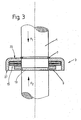
- FIG. 3 shows a modification of FIG. 1 in that only one support element 3 is used in conjunction with an annular securing element 7, which is elastically expandable, and a securing element 9, which is plastically deformed into a groove 13 of the piston rod 1.
- the support member has for the first load direction with the force F1 via an annular support surface 25 and for the force from the second load direction via oppositely oriented support surfaces 27 on a sleeve portion which are arranged on a larger diameter than the second securing element 9.
- the plastically deformed securing element only has to absorb the load from the first load direction, so that the shape of the annular groove in the piston rod 1 can be optimized accordingly.
- Fig. 4 is again only to illustrate that instead of a disc spring assembly between the support member 3 and the second securing element 9 and an elastomeric body can be clamped as a spring element to compensate for any manufacturing tolerances.
Landscapes
- Engineering & Computer Science (AREA)
- General Engineering & Computer Science (AREA)
- Mechanical Engineering (AREA)
- Fluid-Damping Devices (AREA)
- Pistons, Piston Rings, And Cylinders (AREA)
- Actuator (AREA)
Description
- Die Erfindung betrifft ein Kolben-Zylinderaggregat gemäß dem Oberbegriff von Patentanspruch 1.
- Aus der DE 77 03 395 U1 ist ein Stoßdämpfer mit einem Zuganschlag bekannt, wobei ein Stützelement formschlüssig mit der Kolbenstange verbunden ist. Die Kolbenstange verfügt über eine umlaufende Nut, in die Teile des Stützelements verformt werden. In Ausfahrrichtung der Kolbenstange stützt sich das Stützelement mit seinen verformten Volumenteilen in der umlaufenden Nut ab. Bei einer Belastung auf das Stützelement in Einfahrrichtung der Kolbenstange kann ein Absatz der Kolbenstange als Stützfläche genutzt werden. Der Absatz der Kolbenstange wirkt sich als erheblicher Materialeinsatz und damit kostentreibend aus.
- Bei einer Alternativausführung wird anstelle des einteiligen Stützelements ein zusätzliches Sicherungselement verwendet, auf dem sich ein separates Stützelement mit einem Absatz zur Kammerung des Sicherungselements abstützt.
- Die DE 26 55 705 B2 beschreibt einen hydraulischen Teleskopschwingungsdämpfer mit einem elastischen Zuganschlag, bei dem ein Sicherungselement ein Stützelement trägt, das in beiden axialen Richtungen das Stützelement umgreift. Dazu ist das Stützelement mit einer Bördelung versehen. Bei einem plastisch verformten Stützelement besteht der technische Widerspruch, dass der Werkstoff einerseits gut verformbar sein soll, jedoch nach der gewünschten Verformung möglichst große Kräfte übertragen muss.
- Aufgabe der vorliegenden Erfindung ist es, ein Stützelement für ein Kolben-Zylinderaggregat derart weiterzuentwickeln, dass große Belastungen in zwei Richtungen abgestützt werden können.
- Erfindungsgemäß wird die Aufgabe dadurch gelöst, dass das Stützelement zwei ringförmige Sicherungselemente aufweist, wobei jedes der beiden Sicherungselemente bei einer wechselnden Belastung der Kolbenstange in nur eine Richtung belastet wird.
- Vorteilhafte Weiterentwicklungen sind in den Unteransprüchen beschrieben.
- Anhand der folgenden Figurenbeschreibung soll die Erfindung näher erläutert werden.
- Es zeigt:
- Fig. 1 - 4
- Zwei Stützelemente in Verbindung mit zwei Sicherungselementen
- Die Fig. 1 beschränkt sich in ihrer Darstellung auf eine Kolbenstange 1 eines Kolben-Zylinderaggregates, insbesondere eines Schwingungsdämpfers. Die Kolbenstange trägt zwei Stützelemente 3;5, die sich an Sicherungselementen 7;9, die jeweils in eine Ringnut 11;13 der Kolbenstange eingreifen, abstützen. Unterhalb eines ersten Sicherungselements 7 ist ein erstes Stützelement 3 angeordnet. In einem Abstand zum ersten Sicherungselement 3 stützt sich ein zweites Stützelement 5 auf einem zweiten Sicherungselement 9 ab. Zwischen den beiden Stützelementen ist ein Federelement 15 angeordnet. In diesem Fall wird das Federelement von einem Tellerfederpaket gebildet, das die beiden Stützelemente gegen die Sicherungselemente vorspannt. Auf der Oberseite des ersten und der Unterseite des zweiten Stützelements ist jeweils ein Federkörper 17;19 angeordnet.
- Bei einer Belastung der Kolbenstange mit dem Kraftvektor F1 wird die Kraft über den Federkörper auf das erste Stützelement übertragen, der sich ggf. geringfügig gegen die Kraft des Federelements axial verschieben kann. Der Kraftfluss setzt sich über das Federelement und das zweite Anschlagselement auf das zweite Sicherungselement fort.
- Eine Belastung mit dem Kraftvektor F2 führt dazu, dass der Federkörper die Belastung auf das zweite Stützelement überträgt und die Kraft weiter über das Federelement auf das erste Stützelement in Verbindung mit dem Sicherungselement geführt wird. Folglich wird jedes der Sicherungselemente 7;9 auch bei wechselnden Belastungsrichtungen nur in eine Richtung belastet, da beide Stützelemente 7;9 als Stützfläche eine halbseitig offene Rinne 21;23 aufweisen, die sich an dem jeweiligen Sicherungselement abstützt.
- Mit der Figur. 2 soll dokumentiert werden, dass das Federelement 15 zwischen den Stützelementen 3;5 auch von einem Elastomerkörper gebildet werden kann. Bei einem Elastomerkörper ist auf jeden Fall eine Beschädigung der Kolbenstangenoberfläche ausgeschlossen.
- Die Figur 3 zeigt eine Abwandlung der Figur 1, indem nur ein Stützelement 3 in Verbindung mit einem ringförmigen Sicherungselement 7, das elastische aufweitbar ist, und einem Sicherungselement 9, das plastisch in eine Nut 13 der Kolbenstange 1 verformt wird, zur Anwendung kommt. Das Stützelement verfügt für die erste Belastungsrichtung mit der Kraft F1 über eine kreisringförmige Stützfläche 25 und für die Kraft aus der zweiten Belastungsrichtung über entgegengesetzt orientierte Stützflächen 27 auf einem Hülsenabschnitt, die auf einem größeren Durchmesser angeordnet sind als das zweite Sicherungselement 9. Das plastisch verformte Sicherungselement muss nur die Belastung aus der ersten Belastungsrichtung aufnehmen, so dass die Form der Ringnut in der Kolbenstange 1 entsprechend optimiert werden kann.
- Die Fig. 4 soll wiederum nur verdeutlichen, dass anstelle eines Tellerfederpakets zwischen dem Stützelement 3 und dem zweiten Sicherungselement 9 auch ein Elastomerkörper als Federelement eingespannt sein kann, um etwaige Fertigungstoleranzen auszugleichen.
Claims (8)
- Kolben-Zylinderaggregat, umfassend eine axial bewegliche Kolbenstange, an der zumindest ein Stützelement angeordnet ist, wobei zwischen dem Stützelement und der Kolbenstange eine Formschluss-Verbindung vorliegt, indem ein Sicherungselement des Stützelementes in eine Ringnut der Kolbenstange eingreift,
dadurch gekennzeichnet,
dass das Stützelement (3;5) zwei ringförmige Sicherungselemente (7;9) aufweist, wobei jedes der beiden Sicherungselemente (7;9) bei einer wechselnden Belastung der Kolbenstange in nur eine Richtung belastet wird. - Kolben-Zylinderaggregat nach Anspruch 1,
dadurch gekennzeichnet,
dass gegen die Belastungsrichtung des Stützelements (3;5) jeweils ein Sicherungselement (7;9) ausgeführt ist und für jedes der beiden Sicherungselemente (7;9) am Stützelement (3;5) nur eine in Belastungsrichtung verlaufende Stützfläche (21;23) vorgesehen ist. - Kolben-Zylinderaggregat nach Anspruch 2,
dadurch gekennzeichnet,
dass zwei Stützelemente (3;5) verwendet werden, wobei sich jeweils ein Stützelement (3;5) an einem Sicherungselement (7:9) abstützt und zwischen den beiden Stützelementen (3;5) mindestens ein Federelement (15) angeordnet ist. - Kolben-Zylinderaggregat nach Anspruch 3,
dadurch gekennzeichnet,
dass das Federelement (15) von mindestens einer Tellerfeder gebildet wird. - Kolben-Zylinderaggregat nach Anspruch 3,
dadurch gekennzeichnet,
dass das Federelement (15) von einem Elastomerkörper gebildet wird. - Kolben-Zylinderaggregat nach Anspruch 1,
dadurch gekennzeichnet,
dass das Stützelement (3) für eine erste Belastungsrichtung eine kreisringförmige Stützfläche (25) aufweist und auf einen größeren Durchmesser als das zweite Sicherungselement (9) für die zweite Belastungsrichtung entgegengesetzt orientierte Stützflächen (27) verfügt. - Kolben-Zylinderaggregat nach Anspruch 6,
dadurch gekennzeichnet,
dass die Stützflächen (17) für die zweite Belastungsrichtung von einem Hülsenabschnitt des Stützelements (3) gebildet werden. - Kolben-Zylinderaggregat nach Anspruch 1,
dadurch gekennzeichnet,
dass das zweite Sicherungselement (9) plastisch in eine Nut (11) der Kolbenstange (1) verformt ist, wobei das zweite Sicherungselement nur Belastungen aus der ersten Belastungsrichtung aufnimmt.
Applications Claiming Priority (2)
| Application Number | Priority Date | Filing Date | Title |
|---|---|---|---|
| DE10228223A DE10228223A1 (de) | 2002-06-25 | 2002-06-25 | Anschlagring für ein Kolben-Zylinderaggregat |
| DE10228223 | 2002-06-25 |
Publications (3)
| Publication Number | Publication Date |
|---|---|
| EP1375958A2 EP1375958A2 (de) | 2004-01-02 |
| EP1375958A3 EP1375958A3 (de) | 2004-11-10 |
| EP1375958B1 true EP1375958B1 (de) | 2007-01-24 |
Family
ID=29716632
Family Applications (1)
| Application Number | Title | Priority Date | Filing Date |
|---|---|---|---|
| EP03010963A Expired - Lifetime EP1375958B1 (de) | 2002-06-25 | 2003-05-16 | Anschlagring für ein Kolben-Zylinderaggregat |
Country Status (3)
| Country | Link |
|---|---|
| EP (1) | EP1375958B1 (de) |
| AT (1) | ATE352731T1 (de) |
| DE (2) | DE10228223A1 (de) |
Families Citing this family (5)
| Publication number | Priority date | Publication date | Assignee | Title |
|---|---|---|---|---|
| DE20319511U1 (de) * | 2003-12-16 | 2005-04-28 | Al-Ko Kober Ag | Stoßdämpfer mit Anschlag |
| DE102004007960B4 (de) * | 2004-02-18 | 2007-08-09 | Zf Friedrichshafen Ag | Kolben-Zylinder-Aggregat |
| JP6340233B2 (ja) * | 2014-04-08 | 2018-06-06 | Kyb株式会社 | シリンダ装置 |
| DE102016207324A1 (de) * | 2016-04-28 | 2017-11-02 | Volkswagen Aktiengesellschaft | Zuganschlag für eine Kolbenstange |
| DE102019215561A1 (de) * | 2019-10-10 | 2021-04-15 | Zf Friedrichshafen Ag | Drosselstelle für einen Schwingungsdämpfer |
Family Cites Families (10)
| Publication number | Priority date | Publication date | Assignee | Title |
|---|---|---|---|---|
| DE7408730U (de) * | 1974-06-12 | Fortmeier J | Vorrichtung zum Befestigen eines Kolbens auf einer Kolbenstange | |
| DE1804037A1 (de) * | 1968-10-19 | 1970-04-30 | Teves Gmbh Alfred | Hydraulik-Reservoir |
| DE6906019U (de) * | 1969-02-13 | 1969-06-04 | Deere & Co | Anordnung zur loesbaren verbindung eines kolbens auf einer kolbenstange |
| DE2655705C3 (de) * | 1976-12-09 | 1980-06-12 | Boge Gmbh, 5208 Eitorf | Hydraulischer Teleskopschwingungsdampfer mit hydraulischem und elastischem Zuganschlag, insbesondere fur Kraftfahrzeuge |
| DE7703395U1 (de) * | 1977-02-05 | 1977-09-08 | Fichtel & Sachs Ag, 8720 Schweinfurt | Stoßdämpfer für Kraftfahrzeuge mit Zuganschlag |
| US5024301A (en) * | 1990-05-23 | 1991-06-18 | Ford Motor Company | Hydraulic rebound stop assembly for a shock absorber |
| DE4332296C5 (de) * | 1993-01-22 | 2008-08-07 | Stabilus Gmbh | Pneumatisches, hydraulisches oder hydropneumatisches Aggregat |
| JPH0942364A (ja) * | 1995-07-31 | 1997-02-10 | Kayaba Ind Co Ltd | ショックアブソーバ |
| DE20021481U1 (de) * | 2000-12-19 | 2001-06-13 | PP-Plastic Peuker OHG, 08459 Neukirchen | Federwegbegrenzungselement |
| DE10105101C1 (de) * | 2001-02-05 | 2002-12-12 | Zf Sachs Ag | Hydraulischer Zuganschlag für Schwingungsdämpfer |
-
2002
- 2002-06-25 DE DE10228223A patent/DE10228223A1/de not_active Ceased
-
2003
- 2003-05-16 DE DE50306352T patent/DE50306352D1/de not_active Expired - Lifetime
- 2003-05-16 EP EP03010963A patent/EP1375958B1/de not_active Expired - Lifetime
- 2003-05-16 AT AT03010963T patent/ATE352731T1/de not_active IP Right Cessation
Also Published As
| Publication number | Publication date |
|---|---|
| EP1375958A3 (de) | 2004-11-10 |
| DE50306352D1 (de) | 2007-03-15 |
| DE10228223A1 (de) | 2004-01-22 |
| ATE352731T1 (de) | 2007-02-15 |
| EP1375958A2 (de) | 2004-01-02 |
Similar Documents
| Publication | Publication Date | Title |
|---|---|---|
| EP2042771B2 (de) | Schwingungsdämpfer mit einem Zuganschlag | |
| DE112013004246B4 (de) | Zylindrische Schwingungsdämpfungsvorrichtung | |
| EP2195549B1 (de) | Geberzylinder, insbesondere für die kupplungs- oder bremsbetätigung eines kraftfahrzeuges | |
| DE102019215561A1 (de) | Drosselstelle für einen Schwingungsdämpfer | |
| EP1031756A2 (de) | Befestigung eines Luftfeder-Rollbalges an einem Stützteil | |
| EP1693233A1 (de) | Luftfederbein mit zentrisch angeordnetem Dämpfer | |
| EP0472828A2 (de) | Lagerung für einen Gangschalthebel | |
| DE1920242A1 (de) | Kupplungsscheibe | |
| EP0444321A1 (de) | Rollbalg-Luftfeder mit einem Schlauchrollbalg aus elastorem Werkstoff | |
| EP1878937B1 (de) | Elastisches Fahrwerkslager | |
| WO1996037713A1 (de) | Druckfeder für eine ausrückeinheit von fahrzeugkupplungen | |
| DE102006005621B4 (de) | Anschlagfeder für ein Kolben-Zylinderaggregat | |
| DE102008010541A1 (de) | Federbein- oder Stoßdämpferabstützung für ein Fahrzeugrad | |
| EP3110680B1 (de) | Lenkwelle für ein kraftfahrzeug | |
| DE10344102B3 (de) | Federträger mit einer Zusatzfeder | |
| EP1375958A2 (de) | Anschlagring für ein Kolben-Zylinderaggregat | |
| EP1650467B1 (de) | Schwingungsdämpfer | |
| DE69903376T2 (de) | Federnde Stützeinrichtung für die Abgasleitung eines Kraftfahrzeugs | |
| DE102005001740B3 (de) | Federbein mit einem höhenverstellbaren Federteller | |
| EP2060832B1 (de) | Klemmkontur für ein druckbeaufschlagbares Bauteil und Spannmittel dafür | |
| EP0482282B1 (de) | Axial-Buchsenlager | |
| DE10346343B4 (de) | An einer Radnabe befestigbare Bremsscheibe | |
| DE10041993C1 (de) | Tilger mit einer Tilgermasse, einer Elastomerfeder, einer Basis und einem Befestigungsbolzen | |
| DE102021213759A1 (de) | Federtelleranordnung mit Verdrehsicherung sowie Schwinungsdämpfer mit der Federtellanordnung | |
| DE102020210763A1 (de) | Filtervorrichtung zur Dämpfung von Vibrationen in einer Leitung eines hydraulischen Betätigungssystems zum Ausrücken einer Kupplung |
Legal Events
| Date | Code | Title | Description |
|---|---|---|---|
| PUAI | Public reference made under article 153(3) epc to a published international application that has entered the european phase |
Free format text: ORIGINAL CODE: 0009012 |
|
| AK | Designated contracting states |
Kind code of ref document: A2 Designated state(s): AT BE BG CH CY CZ DE DK EE ES FI FR GB GR HU IE IT LI LU MC NL PT RO SE SI SK TR |
|
| AX | Request for extension of the european patent |
Extension state: AL LT LV MK |
|
| PUAL | Search report despatched |
Free format text: ORIGINAL CODE: 0009013 |
|
| AK | Designated contracting states |
Kind code of ref document: A3 Designated state(s): AT BE BG CH CY CZ DE DK EE ES FI FR GB GR HU IE IT LI LU MC NL PT RO SE SI SK TR |
|
| AX | Request for extension of the european patent |
Extension state: AL LT LV MK |
|
| 17P | Request for examination filed |
Effective date: 20041012 |
|
| 17Q | First examination report despatched |
Effective date: 20050314 |
|
| AKX | Designation fees paid |
Designated state(s): AT BE BG CH CY CZ DE DK EE ES FI FR GB GR HU IE IT LI LU MC NL PT RO SE SI SK TR |
|
| GRAP | Despatch of communication of intention to grant a patent |
Free format text: ORIGINAL CODE: EPIDOSNIGR1 |
|
| GRAS | Grant fee paid |
Free format text: ORIGINAL CODE: EPIDOSNIGR3 |
|
| GRAA | (expected) grant |
Free format text: ORIGINAL CODE: 0009210 |
|
| AK | Designated contracting states |
Kind code of ref document: B1 Designated state(s): AT BE BG CH CY CZ DE DK EE ES FI FR GB GR HU IE IT LI LU MC NL PT RO SE SI SK TR |
|
| PG25 | Lapsed in a contracting state [announced via postgrant information from national office to epo] |
Ref country code: SI Free format text: LAPSE BECAUSE OF FAILURE TO SUBMIT A TRANSLATION OF THE DESCRIPTION OR TO PAY THE FEE WITHIN THE PRESCRIBED TIME-LIMIT Effective date: 20070124 Ref country code: FI Free format text: LAPSE BECAUSE OF FAILURE TO SUBMIT A TRANSLATION OF THE DESCRIPTION OR TO PAY THE FEE WITHIN THE PRESCRIBED TIME-LIMIT Effective date: 20070124 Ref country code: NL Free format text: LAPSE BECAUSE OF FAILURE TO SUBMIT A TRANSLATION OF THE DESCRIPTION OR TO PAY THE FEE WITHIN THE PRESCRIBED TIME-LIMIT Effective date: 20070124 Ref country code: DK Free format text: LAPSE BECAUSE OF FAILURE TO SUBMIT A TRANSLATION OF THE DESCRIPTION OR TO PAY THE FEE WITHIN THE PRESCRIBED TIME-LIMIT Effective date: 20070124 Ref country code: IE Free format text: LAPSE BECAUSE OF FAILURE TO SUBMIT A TRANSLATION OF THE DESCRIPTION OR TO PAY THE FEE WITHIN THE PRESCRIBED TIME-LIMIT Effective date: 20070124 |
|
| REG | Reference to a national code |
Ref country code: GB Ref legal event code: FG4D Free format text: NOT ENGLISH |
|
| REG | Reference to a national code |
Ref country code: CH Ref legal event code: EP |
|
| REG | Reference to a national code |
Ref country code: IE Ref legal event code: FG4D Free format text: LANGUAGE OF EP DOCUMENT: GERMAN |
|
| REF | Corresponds to: |
Ref document number: 50306352 Country of ref document: DE Date of ref document: 20070315 Kind code of ref document: P |
|
| PG25 | Lapsed in a contracting state [announced via postgrant information from national office to epo] |
Ref country code: SE Free format text: LAPSE BECAUSE OF FAILURE TO SUBMIT A TRANSLATION OF THE DESCRIPTION OR TO PAY THE FEE WITHIN THE PRESCRIBED TIME-LIMIT Effective date: 20070424 |
|
| PG25 | Lapsed in a contracting state [announced via postgrant information from national office to epo] |
Ref country code: BG Free format text: LAPSE BECAUSE OF EXPIRATION OF PROTECTION Effective date: 20070425 |
|
| PG25 | Lapsed in a contracting state [announced via postgrant information from national office to epo] |
Ref country code: ES Free format text: LAPSE BECAUSE OF FAILURE TO SUBMIT A TRANSLATION OF THE DESCRIPTION OR TO PAY THE FEE WITHIN THE PRESCRIBED TIME-LIMIT Effective date: 20070505 |
|
| PG25 | Lapsed in a contracting state [announced via postgrant information from national office to epo] |
Ref country code: PT Free format text: LAPSE BECAUSE OF FAILURE TO SUBMIT A TRANSLATION OF THE DESCRIPTION OR TO PAY THE FEE WITHIN THE PRESCRIBED TIME-LIMIT Effective date: 20070625 |
|
| NLV1 | Nl: lapsed or annulled due to failure to fulfill the requirements of art. 29p and 29m of the patents act | ||
| GBV | Gb: ep patent (uk) treated as always having been void in accordance with gb section 77(7)/1977 [no translation filed] |
Effective date: 20070124 |
|
| REG | Reference to a national code |
Ref country code: IE Ref legal event code: FD4D |
|
| EN | Fr: translation not filed | ||
| PG25 | Lapsed in a contracting state [announced via postgrant information from national office to epo] |
Ref country code: SK Free format text: LAPSE BECAUSE OF FAILURE TO SUBMIT A TRANSLATION OF THE DESCRIPTION OR TO PAY THE FEE WITHIN THE PRESCRIBED TIME-LIMIT Effective date: 20070124 Ref country code: GB Free format text: LAPSE BECAUSE OF FAILURE TO SUBMIT A TRANSLATION OF THE DESCRIPTION OR TO PAY THE FEE WITHIN THE PRESCRIBED TIME-LIMIT Effective date: 20070124 |
|
| PLBE | No opposition filed within time limit |
Free format text: ORIGINAL CODE: 0009261 |
|
| STAA | Information on the status of an ep patent application or granted ep patent |
Free format text: STATUS: NO OPPOSITION FILED WITHIN TIME LIMIT |
|
| BERE | Be: lapsed |
Owner name: ZF SACHS A.G. Effective date: 20070531 |
|
| 26N | No opposition filed |
Effective date: 20071025 |
|
| PG25 | Lapsed in a contracting state [announced via postgrant information from national office to epo] |
Ref country code: CZ Free format text: LAPSE BECAUSE OF FAILURE TO SUBMIT A TRANSLATION OF THE DESCRIPTION OR TO PAY THE FEE WITHIN THE PRESCRIBED TIME-LIMIT Effective date: 20070124 Ref country code: RO Free format text: LAPSE BECAUSE OF FAILURE TO SUBMIT A TRANSLATION OF THE DESCRIPTION OR TO PAY THE FEE WITHIN THE PRESCRIBED TIME-LIMIT Effective date: 20070124 |
|
| REG | Reference to a national code |
Ref country code: CH Ref legal event code: PL |
|
| PG25 | Lapsed in a contracting state [announced via postgrant information from national office to epo] |
Ref country code: MC Free format text: LAPSE BECAUSE OF NON-PAYMENT OF DUE FEES Effective date: 20070531 |
|
| PG25 | Lapsed in a contracting state [announced via postgrant information from national office to epo] |
Ref country code: LI Free format text: LAPSE BECAUSE OF NON-PAYMENT OF DUE FEES Effective date: 20070531 Ref country code: CH Free format text: LAPSE BECAUSE OF NON-PAYMENT OF DUE FEES Effective date: 20070531 |
|
| PG25 | Lapsed in a contracting state [announced via postgrant information from national office to epo] |
Ref country code: BE Free format text: LAPSE BECAUSE OF NON-PAYMENT OF DUE FEES Effective date: 20070531 |
|
| PG25 | Lapsed in a contracting state [announced via postgrant information from national office to epo] |
Ref country code: IT Free format text: LAPSE BECAUSE OF FAILURE TO SUBMIT A TRANSLATION OF THE DESCRIPTION OR TO PAY THE FEE WITHIN THE PRESCRIBED TIME-LIMIT Effective date: 20070124 Ref country code: GR Free format text: LAPSE BECAUSE OF FAILURE TO SUBMIT A TRANSLATION OF THE DESCRIPTION OR TO PAY THE FEE WITHIN THE PRESCRIBED TIME-LIMIT Effective date: 20070425 Ref country code: FR Free format text: LAPSE BECAUSE OF FAILURE TO SUBMIT A TRANSLATION OF THE DESCRIPTION OR TO PAY THE FEE WITHIN THE PRESCRIBED TIME-LIMIT Effective date: 20070914 |
|
| PG25 | Lapsed in a contracting state [announced via postgrant information from national office to epo] |
Ref country code: AT Free format text: LAPSE BECAUSE OF NON-PAYMENT OF DUE FEES Effective date: 20070516 |
|
| PG25 | Lapsed in a contracting state [announced via postgrant information from national office to epo] |
Ref country code: FR Free format text: LAPSE BECAUSE OF FAILURE TO SUBMIT A TRANSLATION OF THE DESCRIPTION OR TO PAY THE FEE WITHIN THE PRESCRIBED TIME-LIMIT Effective date: 20070124 |
|
| PG25 | Lapsed in a contracting state [announced via postgrant information from national office to epo] |
Ref country code: EE Free format text: LAPSE BECAUSE OF FAILURE TO SUBMIT A TRANSLATION OF THE DESCRIPTION OR TO PAY THE FEE WITHIN THE PRESCRIBED TIME-LIMIT Effective date: 20070124 |
|
| PG25 | Lapsed in a contracting state [announced via postgrant information from national office to epo] |
Ref country code: CY Free format text: LAPSE BECAUSE OF FAILURE TO SUBMIT A TRANSLATION OF THE DESCRIPTION OR TO PAY THE FEE WITHIN THE PRESCRIBED TIME-LIMIT Effective date: 20070124 |
|
| PG25 | Lapsed in a contracting state [announced via postgrant information from national office to epo] |
Ref country code: LU Free format text: LAPSE BECAUSE OF NON-PAYMENT OF DUE FEES Effective date: 20070516 |
|
| PG25 | Lapsed in a contracting state [announced via postgrant information from national office to epo] |
Ref country code: HU Free format text: LAPSE BECAUSE OF FAILURE TO SUBMIT A TRANSLATION OF THE DESCRIPTION OR TO PAY THE FEE WITHIN THE PRESCRIBED TIME-LIMIT Effective date: 20070725 Ref country code: TR Free format text: LAPSE BECAUSE OF FAILURE TO SUBMIT A TRANSLATION OF THE DESCRIPTION OR TO PAY THE FEE WITHIN THE PRESCRIBED TIME-LIMIT Effective date: 20070124 |
|
| PGFP | Annual fee paid to national office [announced via postgrant information from national office to epo] |
Ref country code: DE Payment date: 20100512 Year of fee payment: 8 |
|
| REG | Reference to a national code |
Ref country code: DE Ref legal event code: R119 Ref document number: 50306352 Country of ref document: DE Effective date: 20111201 |
|
| PG25 | Lapsed in a contracting state [announced via postgrant information from national office to epo] |
Ref country code: DE Free format text: LAPSE BECAUSE OF NON-PAYMENT OF DUE FEES Effective date: 20111201 |