EP2042771B2 - Schwingungsdämpfer mit einem Zuganschlag - Google Patents
Schwingungsdämpfer mit einem Zuganschlag Download PDFInfo
- Publication number
- EP2042771B2 EP2042771B2 EP08016520.2A EP08016520A EP2042771B2 EP 2042771 B2 EP2042771 B2 EP 2042771B2 EP 08016520 A EP08016520 A EP 08016520A EP 2042771 B2 EP2042771 B2 EP 2042771B2
- Authority
- EP
- European Patent Office
- Prior art keywords
- spring
- zuganschlagfeder
- support
- traction
- stop spring
- Prior art date
- Legal status (The legal status is an assumption and is not a legal conclusion. Google has not performed a legal analysis and makes no representation as to the accuracy of the status listed.)
- Active
Links
Images
Classifications
-
- F—MECHANICAL ENGINEERING; LIGHTING; HEATING; WEAPONS; BLASTING
- F16—ENGINEERING ELEMENTS AND UNITS; GENERAL MEASURES FOR PRODUCING AND MAINTAINING EFFECTIVE FUNCTIONING OF MACHINES OR INSTALLATIONS; THERMAL INSULATION IN GENERAL
- F16F—SPRINGS; SHOCK-ABSORBERS; MEANS FOR DAMPING VIBRATION
- F16F9/00—Springs, vibration-dampers, shock-absorbers, or similarly-constructed movement-dampers using a fluid or the equivalent as damping medium
- F16F9/32—Details
- F16F9/58—Stroke limiting stops, e.g. arranged on the piston rod outside the cylinder
- F16F9/585—Stroke limiting stops, e.g. arranged on the piston rod outside the cylinder within the cylinder, in contact with working fluid
Definitions
- the invention relates to a vibration damper for the suspension of a motor vehicle with a mechanical Buchanschlag, which is formed by a trained as a helical spring tension stop spring, which is arranged between two spring plates. The ends of the Weranschlagfeder supported thereby on corresponding support surfaces of the spring plate.
- the support tube 24 is the same length as the block dimension of the Buchanschlagfeder, then the Weranschlagfeder can reach their maximum Blockleton, but not be charged beyond. In both cases, all forces on the support tube 24, the stopper 32, the rubber buffer 33 (rebound rubber 33) and the closure element (cylinder cover 13) are derived. On the Buchanschlagfeder 31 Therefore, the critical, overloading and plastic deformation inducing forces can not act at all.
- the DE 100 21 762 A1 represents a prior art, which does not relate to the technical subject of the present subject matter, but only in the broadest sense of the technical field of damping of movements of components is assigned.
- This document discloses an air damper for a movably mounted component in a car (eg a glove box flap).
- a coil spring is arranged in the cylinder of the air damper. This coil spring is not a Switzerlandanschlagfeder in the sense of the present invention, but it should give the cylinder a preferential adjustment.
- Cylinder and piston of the DE 100 21 762 A1 known air damper are molded from plastic material.
- the DE 100 21 762 A1 addresses the problem that the aforementioned, arranged in the cylinder interior spring can create some problems, especially acoustic problems.
- the spring is referred to as relatively unstable, so that when they are actuated the kink limit is reached very quickly. If the spring kinks, it produces unwanted knocking, friction and buzzing noises. To avoid this is in the DE 100 21 762 A1 proposed that are formed on the piston rod diametrically elongated ribs against which the windings of the spring when it is relaxed.
- the invention has the object, a vibration damper according to the preamble of claim 1 such that a plastic deformation of the Glasanschlagfeder can be safely avoided even if the Buchanschlagfeder driven in a row very high forces acting on them block and even further in the block state is charged. At the same time it should be possible to manufacture the spring plate supporting the Wernerfeder of a material with low specific weight and thus save weight.
- the invention is based on the recognition that, especially in vehicles with high weight and off-road characteristics, very large tensile forces can occur during rebound of the vibration dampers. It is quite realistic that the tensile forces in such vehicles can reach values of up to 45 kN and beyond.
- Conventional Buchanschlagfedern go, however, depending on their spring rate already at much lower forces on block.
- Conventional pull-down forces which result in block drive of the train stop springs may e.g. range between 2 and 6 kN.
- the spring plate on which the ends of the Huaweifeder supported on support surfaces, in addition to these support surfaces to be provided with a further functional surface, namely in the axial direction (ie in the longitudinal direction of the vibration damper) extending support sleeves whose outer lateral surfaces completely support the tension stop spring radially inwards when the tension stop spring is moved to block or is.
- the idea according to the invention therefore consists in integrating an additional function, namely the function of the radial support of the tension stop spring from the inside, into the spring plate supporting the tension stop spring in the axial direction.
- the support sleeves do not touch each other when the Huaweianschlagfeder has moved to block, so that all axial forces occurring are absorbed by the driven on block Anlagenanschlagfeder and derived therefrom. Since the Buchanschlagfeder consists of a steel material, very high axial forces can be absorbed by her in the driven to block state, since they are supported radially from the inside by the support sleeves becomes. This prevents buckling or telescoping of the spring coils even at very high axial forces.
- the spring plates with the support sleeves can therefore advantageously consist of a material with a low specific weight, such as e.g. also plastic or aluminum.
- the axial extension of the support sleeves is dimensioned such that the access point spring driven on the block is supported substantially radially over its entire length from the inside by the lateral surfaces of the support sleeves.
- the present invention is implemented when the diameter of the Buchanschlagfeder is dimensioned so that it only has a relatively small distance from the inner wall of the damper tube in the relaxed state.
- the diameters of the support sleeves are to be dimensioned as a function of the diameter of the tension stop spring such that a radial support of the tension stop spring is ensured from the inside when the tension stop spring has moved to block.
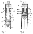
- Fig. 1 the draft stop according to the invention is shown in a relaxed state of the Huaweian Farbfeder 9.
- the Huaweian Farbfeder 9 is supported with its two ends on support surfaces 10 of the spring plate 7, 8 from.
- the spring plate 7 is in turn supported on the working space 3 facing surface of the closure package 6 and is arranged in the axial direction movable on the piston rod 5.
- the other spring plate 8 is screwed onto a threaded pin of the piston rod 5 and thereby firmly connected thereto.
- the lower spring plate 8 can be plugged onto the piston rod pin and clamped by a piston nut or secured by crimping, by a snap ring or by welding on the slide (these alternatives are not shown in the figures).
- the working piston 4 is attached via a nut on a piston rod pin.
- the Switzerlandtschfeder 9 is dimensioned relative to the inner diameter of the damper tube 1 so that in the relaxed state of the spring only a small distance between the Huaweianschlagfeder 9 and the inner wall of the damper tube 1 is present.
- the end remote from the working piston 4 of the Buchanschlagfeder 9 is supported in the axial direction on a support surface 10 of the spring plate 7 from.
- the spring plate 7 has a supporting sleeve 11 extending in the longitudinal direction of the vibration damper.
- the diameter of the support sleeve 11 is dimensioned relative to the diameter of the Buchanschlagfeder 9 so that the outer surface 11a of the support sleeve 11, the Buchanschlagfeder 9 radially from the inside is supported when the Switzerlandanschlagfeder 9 is driven to block (see. Fig. 2 ).
- the spring plate 8 has a extending in the longitudinal direction of the vibration damper support sleeve 12, the lateral surface 12a the Weranschlagfeder 9 radially supported from the inside when the spring is driven to block (see. Fig. 2 ).
- the lateral surface 12a is not simply cylindrical, as the lateral surface 11a of the spring plate 7, but it has a slightly conical shape.
- tapers in the axial direction of the diameter of the support sleeve 12. This conical shape of the lateral surface 12a facilitates insertion of the support sleeve 12 in the Weranschlagfeder 9 and prevents jamming the Switzerlandanschlagfeder 9 on the support sleeve.
- the diameter of the support sleeves 11 and 12 of the spring plate 7, 8 and the diameter of the Weranschlagfeder 9 are dimensioned so that when driven on block Weranschlagfeder 9 between the inner wall of the damper tube 1 and the outer surfaces 11a, 12a of the support sleeves 11, 12, an encapsulated annular space thirteenth is formed, in which the Buchanschlagfeder 9 is held ausknickêt and deformation resistant. Due to the encapsulated arrangement of the driven block on the train stop spring 9 in the annular space 13 is reliably avoided that individual turns of the Weranschlagfeder 9 can escape when exposed to high forces in the radial direction and can be pushed into each other. In this way, a plastic deformation of the tension stop spring 9 audi then reliably prevented when the forces acting on the Weranschlagfeder forces exceed the force at which the Buchanschlagfeder 9 goes to block by a multiple.
- Fig. 2 is, as already mentioned above, the block driven state of the Buchanschlagfeder 9 shown. It is good to see that the support sleeves 11, 12 do not touch each other. The high axial forces are therefore not absorbed and dissipated via the support sleeves 11, 12, but over the driven on block Weranschlagfeder 9. This can not lead to a plastic deformation of the support sleeves 11, 12 due to the axial forces.
- the spring plates 7, 8 can therefore be made of a material which is a much lower specific gravity than steel. In particular, lightweight materials such as plastic or light metal (such as aluminum) can be used to manufacture the spring plates 7, 8, so that weight can be saved.
Landscapes
- Engineering & Computer Science (AREA)
- General Engineering & Computer Science (AREA)
- Mechanical Engineering (AREA)
- Fluid-Damping Devices (AREA)
- Springs (AREA)
- Vehicle Body Suspensions (AREA)
Description
- Die Erfindung betrifft einen Schwingungsdämpfer für die Radaufhängung eines Kraftfahrzeuges mit einem mechanischen Zuganschlag, der durch eine als Schraubenfeder ausgebildete Zuganschlagfeder ausgebildet ist, die zwischen zwei Federtellern angeordnet ist. Die Enden der Zuganschlagfeder stützen sich dabei auf entsprechenden Stützflächen der Federteller ab.
- Ein derartiger, die Merkmale des Oberbegriffs des Patentanspruchs 1 aufweisender Schwingungsdämpfer ist beispielsweise aus der
DE 10 2005 009 213 A1 bekannt. Aus dieser Druckschrift ist es auch bekannt, dass es zu einem Ausknicken der Zuganschlagfeder in Richtung auf die Innenwand des Dämpferrohres kommen kann, insbesondere dann, wenn aus konstruktiven Gründen große Federwege vorgesehen werden müssen. Zur Vermeidung dieses unerwünschten Ausknickens der Zuganschlagfeder wird vorgeschlagen, den Innendurchmesser der Schraubenfederwindungen in einem mittleren Federabschnitt zu reduzieren, so dass das Ausknicken zur Kolbenstange hin erfolgt und sich die Zuganschlagfeder beim Ausknicken an die Kolbenstange einlegt. Dadurch wirkt die Kolbenstange als radiale Führung für die Zuganschlagleder. Nachteilig ist bei dieser Lösung, dass eine besondere Formgebung der Zuganschlagfeder erforderlich ist, um das gezielte Ausknicken nach innen, d.h. zur Kolbenstange hin, zu erreichen. Daher können keine einfacheren zylindrischen Federn eingesetzt Werden, die kostengünstiger in Herstellung sind. Nachteilig ist außerdem, dass die Kolbenstangenoberfläche von der Zuganschlagfeder beschädigt werden kann. - Neben dem in der
DE 10 2005 009 213 A1 diskutierten Ausknicken der Zuganschlagfeder nach außen zum Dämpferrohr hin, so hat die Erfahrung gezeigt, kann es dann, wenn die Zuganschlagfeder aufgrund großer auf sie einwirkender Kräfte auf Block gefahren wird, zu einem Ineinanderschieben der einzelnen Windungen der als Schraubenfeder ausgebildeten Zuganschlagfeder kommen. Dabei weichen die Federwindungen in radialer Richtung nach innen oder außen aus, so dass dieses Ineinanderschieben der einzelnen Federwindungen zu plastischen Verformungen der Federführt, wenn die einwirkende Kraft groß genug ist. Die Funktion und die Dauerfestigkeit der Zuganschlagfeder sind dann nicht mehr gegeben. In Bezug auf dieses unerwünschte, ein technisches Versagen bewirkende plastische Verformen der Zuganschlagfeder sind in derDE 10 2005 009 213 A1 keine Gegenmaßnahmen offenbart. - In der Druckschrift
EP 1 591 690 A1 ist ein hydraulischer Schwingungsdämpfer für Kraftfahrzeuge beschrieben (siehe insbesondereFig. 2 und zugehörige Beschreibung), bei dem sich die Zuganschlagfeder (compression coil spring 31) auf dem Flansch (flange 24a) eines Stützrohrs (support pipe 24) abstützt. Die Länge des Stützrohrs ist dabei gemäß Absatz 0033 dieser Druckschrift so bemessen, dass sie gleich groß oder größer ist als die minimale Länge der Zuganschlagfeder an ihrem elastischen Limit, d.h. bei Erreichen ihres Blockmaßes. Dies bedeutet, dass beim Gegenstand derEP 1 591 690 A1 die Zuganschlagfeder nicht über ihr Blockmaß hinaus belastet und zusammengedrückt werden kann. Denn entweder ist das Stützrohr länger als das Blockmaß der Feder, dann stützt sich das Stützrohr 24 ian dem Stopper 32 ab, bevor die Zuganschlagfeder überhaupt ihr Blockmaß erreicht hat. Oder das Stützrohr 24 ist genauso lang wie das Blockmaß der Zuganschlagfeder, dann kann die Zuganschlagfeder maximal ihr Blockmaß erreichen, jedoch nicht darüber hinaus belastet werden. In beiden Fällen werden alle Kräfte über das Stützrohr 24, den Stopper 32, den Gummipuffer 33 (rebound rubber 33) und das Verschlusselement (cylinder cover 13) abgeleitet. Auf die Zuganschlagfeder 31 können daher gar nicht die kritischen, Überbelastungen und plastische Verformungen hervorrufenden Kräfte einwirken. - Ein wichtiger Nachteil der aus der
EP 1 591 690 A1 bekannten Konstruktion besteht darin, dass das Stützrohr 24 mit dem federtellerförmigen Flansch 24a sehr großen Belastungen ausgesetzt sein kann, wenn z.B. bei Fahrzeugen mit großem Gewicht und Offroad-Eigenschaften sehr große Zuganschlagkräfte beim Ausfedern der Schwingungsdämpfer auftreten. Daher muss das Stützrohr bei dieser Konstruktion aus einem Werkstoff bestehen, der die auftretenden Belastungen, Flächenpressungen und Spannungen ertragen kann, ohne sich plastisch zu Verformen. Denn zwischen der Kolbenstange und dem die Zuganschlagfeder abstützenden Federteller sind in der Praxis nur geringe Toleranzen zulässig, und eine plastische Verformung des Federtellers kann z.B. sehr schnell zu einer Beschädigung der Kolbenstange führen. Eine plastische Verformung des Federtellers auch bei sehr hohen Zuganschlagkräften beim Ausfedern des Fahrzeugs muss daher unbedingt vermieden werden. Werkstoffe mit geringem spezifischem Gewicht, wie z.B. Kunststoff oder Leichtmetall (z.B. Aluminium), die der Konstrukteur auf Gründen der Gewichtseinsparung gerne für den Federteller venwenden würde, können daher bei der aus derEP 1 591 690 A1 bekannten Konstruktion nicht eingesetzt werden. - Die
DE 100 21 762 A1 stellt einen Stand der Technik dar, der nicht das technische Sachgebiet des vorliegenden Erfindungsgegenstands betrifft, sondern nur im weitesten Sinne dem technischen Gebiet der Dämpfung von Bewegungen von Bauteilen zuzuordnen ist. Diese Druckschrift offenbart einen Luftdämpfer für ein beweglich gelagertes Bauteil in einem Auto (z.B. eine Handschuhfachklappe). In dem Zylinder des Luftdämpfers ist eine Schraubenfeder angeordnet. Diese Schraubenfeder ist keine Zuganschlagfeder im Sinne der vorliegenden Erfindung, sondern sie soll dem Zylinder eine Vorzugsverstellrichtung verleihen. Zylinder und Kolben des aus derDE 100 21 762 A1 bekannten Luftdämpfers sind aus Kunststoffmaterial geformt. - In der
DE 100 21 762 A1 wird das Problem behandelt, dass die vorgenannte, im Zylinderinnenraum angeordnete Feder einige Probleme, insbesondere Probleme akustischer Art erzeugen kann. Die Feder wird als relativ instabil bezeichnet, so dass bei ihrer Betätigung sehr schnell die Knickgrenze erreicht wird. Knickt die Feder aus, so erzeugt sie unerwünschte Klopf-, Reib- und Schwirrgeräusche. Um dieses zu vermeiden wird in derDE 100 21 762 A1 vorgeschlagen, dass an der Kolbenstange diametral längliche Rippen geformt sind, an welchen die Windungen der Feder anliegen, wenn diese entspannt ist. Die in derDE 100 21 762 A1 offenbarte Lösung ist auf das technische Gebiet der vorliegenden Erfindung, also auf das Gebiet der Schwingungsdämpfer für die Radaufhängungen von Kraftfahrzeugen mit mechanischen Zuganschlägen, nicht anwendbar, denn bei diesen Schwingungsdämpfern, die im Betrieb hohen Kräften ausgesetzt sind, ist die Kolbenstange stets als Metallstange mit einer (in der Regel hartverchromten) Mantelfläche ausgebildet. Das Anformen von länglichen Rippen an die Kolbenstange im Sinne derDE 100 21 762 A1 kommt daher nicht in Betracht. - Ausgehend von dem Stand der Technik der
DE 10 2005 009 213 A1 liegt der Erfindung die Aufgabe zugrunde, einen Schwingungsdämpfer gemäß dem Oberbegriff des Patentanspruchs 1 derart weiterzubilden, dass eine plastische Verformung der Zuganschlagfeder auch dann sicher vermieden werden kann, wenn die Zuganschlagfeder in Folge sehr hoher auf sie einwirkender Kräfte auf Block gefahren und im Blockzustand noch weiter belastet wird. Gleichzeitig soll es möglich sein, die die Zuganschlagfeder abstützenden Federteller aus einem Werkstoff mit geringem spezifischem Gewicht zu fertigen und so Gewicht einzusparen. - Diese Aufgabe wird mit einem Schwingungsdämpfer mit den Merkmalen des Patentanspruchs 1 gelöst. Vorteilhafte Weiterbildungen sind in den Unteransprüchen angegeben.
- Die Erfindung geht von der Erkenntnis aus, dass insbesondere bei Fahrzeugen mit großem Gewicht und Offroad-Eigenschaften sehr große Zugarischlagkräfte beim Ausfedern der Schwingungsdämpfer auftreten können. Es ist durchaus realistisch, dass die Zuganschlagkräfte bei solchen Fahrzeugen Werte von bis zu 45 kN und auch darüber hinaus annehmen können. Herkömmliche Zuganschlagfedern gehen jedoch in Abhängigkeit von ihrer Federrate bereits bei viel geringeren Kräften auf Block. Übliche Zuganschlagkräfte, die zu einem auf Block Fahren der Zuganschlagfedern führen, können z.B. im Bereich zwischen 2 und 6 kN liegen. Übersteigt eine auf die Feder einwirkende Zuganschlagkraft den Kraftwert, bei dem die Feder auf Block gefahren ist, so wirken diese Kräfte auf die auf Block gefahrene Feder ein. Dies kann dazu führen, dass die einzelnen Windungen der Zuganschlagfeder in radialer Richtung ausweichen, d.h. die Windungen schieben sich ineinander. Dadurch wird die Feder plastisch verformt, was zu einem Verlust der Funktion bzw. zu einem Versagen der Feder führt.
- Ausgehend von der voranstehend dargelegten Erkenntnis wird erfindungsgemäß vorgeschlagen, die Federteller, auf denen sich die Enden der Zuganschlagfeder auf Stützflächen abstützen, zusätzlich zu diesen Stützflächen mit einer weiteren Funktionsfläche zu versehen, nämlich mit sich in axialer Richtung (d.h. in Längsrichtung des Schwingungsdämpfers) erstreckenden Stützhülsen, deren äußere Mantelflächen die Zuganschlagfeder radial nach innen komplett abstützen, wenn die Zuganschlagfeder auf Block gefahren wird oder ist. Die erfindungsgemäße Idee besteht also darin, eine zusätzliche Funktion, nämlich die Funktion des radialen Abstützens der Zuganschlagfeder von innen, in die die Zuganschlagfeder in axialer Richtung abstützenden Federteller zu integrieren. Erfindungsgemäß berühren die Stützhülsen einander nicht, wenn die Zuganschlagfeder auf Block gefahren ist, so dass alle auftretenden axialen Kräfte von der auf Block gefahrenen Zuganschlagfeder aufgenommen und über diese abgeleitet werden. Da die Zuganschlagfeder aus einem Stahlwerkstoff besteht, können von ihr in dem auf Block gefahrenen Zustand auch sehr hohe axiale Kräfte aufgenommen werden, da sie radial von innen durch die Stützhülsen abgestützt wird. Dadurch wird ein Ausknicken oder ein Ineinanderschieben der Federwindungen auch bei sehr hohen axialen Kräften verhindert.
- Da die Stützhülsen der Federteller einander nicht berühren, wenn die Feder auf Block gefahren ist, werden keine axialen Kräfte durch die Stützhülsen aufgenommen. Die Federteller mit den Stützhülsen können daher vorteilhaft aus einem Werkstoff mit geringem spezifischem Gewicht bestehen, wie z.B. auch Kunststoff oder Aluminium.
- Nach der Erfindung wird die axiale Erstrekkung der Stützhülsen so dimensioniert, dass die auf Block gefahrene Zugänschlagfeder im Wesentlichen über ihre gesamte Länge radial von innen durch die Mantelflächen der Stützhülsen abgestützt wird. Besonders effektiv wird die vorliegende Erfindung umgesetzt, wenn der Durchmesser der Zuganschlagfeder so bemessen wird, dass sie im entspannten Zustand nur einen relativ geringen Abstand von der Innenwand des Dämpferrohres aufweist. Gleichzeitig sind die Durchmesser der Stützhülsen so in Abhängigkeit vom Durchmesser der Zuganschlagfeder zu dimensionieren, dass eine radiale Abstützung der Zuganschlagfeder von innen gewährleistet ist, wenn die Zuganschlagfeder auf Block gefahren ist. Bei einer derartigen Dimensionierung der Zuganschlagfeder und der Stützhülsen zueinander entsteht im auf Block gefahrenen Zustand der Zuganschlagfeder ein gekapselter Ringraum, in dem die Zuganschlagfeder ausknicksicher und verformungssicher gehalten ist. Zu einem Ineinanderschieben der einzelnen Federwindungen und zu einer daraus resultierenden plastischen Verformung der Feder kann es daher nicht kommen.
- Im Folgenden wird die Erfindung anhand einer Zeichnung näher erläutert. Im Einzelnen zeigen
- Fig. 1
- einen Schwingungsdämpfer mit einem erfindungsgemäßen Zuganschlag im entspannten Zustand der Zuganschlagfeder in einem axialen Halbschnitt;
- Fig. 2
- einen Schwingungsdämpfer mit einem erfindungsgemäßen Zuganschlag bei auf Block gefahrener Zuganschlagfeder in einem axialen Halbschnitt.
- In
Fig. 1 ist der erfindungsgemäße Zuganschlag in einem entspannten Zustand der Zuganschlagfeder 9 dargestellt. Die Zuganschlagfeder 9 stützt sich mit ihren beiden Enden auf Stützflächen 10 der Federteller 7, 8 ab. Der Federteller 7 stützt sich seinerseits auf der dem Arbeitsraum 3 zugewandten Oberfläche des Verschlusspaketes 6 ab und ist in axialer Richtung beweglich auf der Kolbenstange 5 angeordnet. Der andere Federteller 8 ist auf einen Gewindezapfen der Kolbenstange 5 aufgeschraubt und dadurch fest mit dieser verbunden. Alternativ kann der untere Federteller 8 auch auf den Kolbenstangenzapfen aufgesteckt und durch eine Kolbenmutter verklemmt werden oder durch Vercrimpung, durch einen Sprengring oder durch Verschweißung auf der Gleitbahn gesichert werden (diese Alternativen sind in den Figuren jedoch nicht dargestellt). Der Arbeitskolben 4 ist über eine Mutter auf einem Kolbenstangenzapfen befestigt. - Die Zuganschlagfeder 9 ist relativ zum Innendurchmesser des Dämpferrohres 1 so dimensioniert, dass im entspannten Zustand der Feder nur ein geringer Abstand zwischen der Zuganschlagfeder 9 und der Innenwandung des Dämpferrohres 1 vorhanden ist. Das vom Arbeitskolben 4 abgewandte Ende der Zuganschlagfeder 9 stützt sich in axialer Richtung auf einer Stützfläche 10 des Federtellers 7 ab. Gleichzeitig weist der Federteller 7 eine sich in Längsrichtung des Schwingungsdämpfers erstreckende Stützhülse 11 auf. Der Durchmesser der Stützhülse 11 ist dabei relativ zu dem Durchmesser der Zuganschlagfeder 9 so dimensioniert, dass die äußere Mantelfläche 11a der Stützhülse 11 die Zuganschlagfeder 9 radial von innen abstützt, wenn die Zuganschlagfeder 9 auf Block gefahren ist (vgl.
Fig. 2 ). - Das Gleiche gilt für die Stützhülse 12 des dem Arbeitskolben 4 zugeordneten Federtellers 8. Auch der Federteller 8 weist eine sich in Längsrichtung des Schwingungsdämpfers erstreckende Stützhülse 12 auf, deren Mantelfläche 12a die Zuganschlagfeder 9 von innen radial abstützt, wenn die Feder auf Block gefahren ist (vgl.
Fig. 2 ). Im dargestellten Ausführungsbeispiel ist die Mantelfläche 12a nicht einfach zylindrisch ausgebildet, wie die Mantelfläche 11a des Federtellers 7, sondern sie weist eine leicht konische Form auf. Ausgehend von der Stützfläche 10 des Federtellers 8, auf der sich das Ende der Zuganschlagfeder 9 abstützt, verjüngt sich in axialer Richtung der Durchmesser der Stützhülse 12. Diese konische Form der Mantelfläche 12a erleichtert das Einführen der Stützhülse 12 in die Zuganschlagfeder 9 und verhindesrt ein Verklemmen der Zuganschlagfeder 9 auf der Stützhülse 9. - Die Durchmesser der Stützhülsen 11 und 12 der Federteller 7, 8 und der Durchmesser der Zuganschlagfeder 9 sind so dimensioniert, dass bei auf Block gefahrener Zuganschlagfeder 9 zwischen der Innenwand des Dämpferrohres 1 und den Mantelflächen 11a, 12a der Stützhülsen 11, 12 ein gekapselter Ringraum 13 ausgebildet ist, in dem die Zuganschlagfeder 9 ausknicksicher und verformungssicher gehalten ist. Durch die gekapselte Anordnung der auf Block gefahrenen Zuganschlagfeder 9 in dem Ringraum 13 wird sicher vermieden, dass einzelne Windungen der Zuganschlagfeder 9 bei Einwirkung von hohen Kräften in radialer Richtung ausweichen und ineinander geschoben werden können. Auf diese Weise wird eine plastische Verformung der Zuganschlagfeder 9 audi dann sicher verhindert, wenn die auf die Zuganschlagfeder einwirkenden Kräfte die Kraft, bei der die Zuganschlagfeder 9 auf Block geht, um ein Vielfaches übersteigen.
- In
Fig. 2 ist, wie bereits vorstehend erwähnt, der auf Block gefahrene Zustand der Zuganschlagfeder 9 dargestellt. Es ist gut zu erkennen, dass die Stützhülsen 11, 12 einander nicht berühren. Die hohen axialen Kräfte werden daher nicht über die Stützhülsen 11, 12 aufgenommen und abgeleitet, sondern über die auf Block gefahrene Zuganschlagfeder 9. Dadurch kann es nicht zu einer plastischen Verformung der Stützhülsen 11, 12 aufgrund der axialen Kräfte kommen. Die Federteller 7, 8 können daher aus einem Werkstoff gefertigt sein, der ein wesentlich geringeres spezifisches Gewicht aufweist als Stahl. Insbesondere können Leichtbauwerkstoffe wie Kunststoff oder Leichtmetall (wie z.B. Aluminium) zu Herstellung der Federteller 7, 8 verwendet werden, so dass Gewicht eingespart werden kann. -
- 1.
- Dämpferrohr
- 2.
- Arbeitsraum
- 3.
- Arbeitsraum
- 4.
- Arbeitskolben
- 5.
- Kolbenstange
- 6.
- Verschlusspaket
- 7.
- Federteller
- 8.
- Federteller
- 9.
- Zuganschlagfeder
- 10.
- Stützfläche
- 11.
- Stützhülse
- 11a.
- Mantelfläche
- 12.
- Stützhülse
- 12a.
- Mantelfläche
- 13.
- gekapselter Ringraum
Claims (2)
- Schwingungsdämpfer für die Radaufhängung eines Kraftfahrzeuges, mit einem Dämpferrohr (1), einem den Innenraum des Dämpferrohres (1) in zwei Arbeitsräume (2, 3) unterteilenden Arbeitskolben, der an einer Kolbenstange (5) befestigt ist, einem ein offenes Ende des Dämpferrohres (1) verschließenden Verschlusspaket (6), durch das die Kolbenstange (5) hindurchgeführt ist, und mit einer zwischen zwei Federtellern (7, 8) angeordneten, als Schraubenfeder ausgebildeten Zuganschlagfeder (9), wobei sich die Enden der Zuganschlagfeder (9) auf Stützflächen (10) der Federteller (7, 8) abstützen, dadurch gekennzeichnet, dass die Federteller (7, 8) sich in Längsrichtung des Schwingungsdämpfers erstreckende Stützhülsen (11, 12) aufweisen, deren äußere Mantelflächen (11a, 12a) die Zuganschlagfeder (9) von innen in radialer Richtung abstützen, wenn die Zuganschlagfeder (9) auf Block gefahren ist, wobei die Stützhülsen (11, 12) im auf Block gefahrenen Zustand der Zuganschlagfeder (9) einander nicht berühren,
dadurch gekennzeichnet, dass die axialen Erstreckungen der Stützhülsen (11, 12) so dimensioniert sind, dass dann, wenn die Zuganschlagfeder auf Block gefahren ist, eine Abstützung über die gesamte Länge der Zuganschlagfeder durch die Stützhülsen (11,12) gegeben ist. - Schwingungsdämpfer nach Anspruch 1, dadurch gekennzeichnet, dass der Durchmesser der Zuganschlagfeder (9) relativ zum Durchmesser des Dämpferrohres (1) und die Durchmesser der Stützhülsen (11, 12) relativ zum Durchmesser der Zuganschlagfeder (9) so bemessen sind, dass sich im auf Block gefahrenen Zustand der Zuganschlagfeder (9) ein Ringraum (13) bildet, in dem die Zuganschlagfeder (9) ausknicksicher und verformungssicher angeordnet ist.
Applications Claiming Priority (1)
| Application Number | Priority Date | Filing Date | Title |
|---|---|---|---|
| DE102007045892A DE102007045892B4 (de) | 2007-09-25 | 2007-09-25 | Schwingungsdämpfer mit einem Zuganschlag |
Publications (4)
| Publication Number | Publication Date |
|---|---|
| EP2042771A2 EP2042771A2 (de) | 2009-04-01 |
| EP2042771A3 EP2042771A3 (de) | 2009-12-23 |
| EP2042771B1 EP2042771B1 (de) | 2012-02-29 |
| EP2042771B2 true EP2042771B2 (de) | 2018-09-19 |
Family
ID=40121987
Family Applications (1)
| Application Number | Title | Priority Date | Filing Date |
|---|---|---|---|
| EP08016520.2A Active EP2042771B2 (de) | 2007-09-25 | 2008-09-19 | Schwingungsdämpfer mit einem Zuganschlag |
Country Status (5)
| Country | Link |
|---|---|
| US (1) | US20090107781A1 (de) |
| EP (1) | EP2042771B2 (de) |
| AT (1) | ATE547648T1 (de) |
| DE (1) | DE102007045892B4 (de) |
| ES (1) | ES2381310T5 (de) |
Families Citing this family (18)
| Publication number | Priority date | Publication date | Assignee | Title |
|---|---|---|---|---|
| US20120091641A1 (en) * | 2010-10-19 | 2012-04-19 | Ching-Chuan Yang | Air pressure buffer |
| JP5667482B2 (ja) * | 2011-03-17 | 2015-02-12 | カヤバ工業株式会社 | シリンダ装置 |
| JP5435434B2 (ja) * | 2011-06-03 | 2014-03-05 | Smc株式会社 | ピストン組立体、流体圧シリンダ及びピストン組立体の製造方法 |
| JP2014029175A (ja) * | 2012-07-31 | 2014-02-13 | Hitachi Automotive Systems Ltd | 流体圧緩衝器 |
| DE102013207130A1 (de) * | 2013-04-19 | 2014-10-23 | Zf Friedrichshafen Ag | Schwingungsdämpfer |
| US20160298763A1 (en) * | 2015-04-09 | 2016-10-13 | Bendix Commercial Vehicle Systems Llc | Piston assembly for an unloader valve of an air compressor |
| CN106121078B (zh) * | 2016-06-29 | 2018-04-17 | 北京交通大学 | 一种具有复位功能的磁流体变阻尼耗能支撑 |
| JP6169769B1 (ja) * | 2016-10-31 | 2017-07-26 | 株式会社ショーワ | リバウンドスプリング構造 |
| DE102017201854A1 (de) | 2017-02-07 | 2018-08-09 | Zf Friedrichshafen Ag | Endlagenfedervorrichtung für einen Schwingungsdämpfer |
| DE102017112998A1 (de) | 2017-06-13 | 2018-12-13 | Thyssenkrupp Ag | Schwingungsdämpfer |
| US20190195310A1 (en) * | 2017-12-27 | 2019-06-27 | On Top Safety, Inc. | Force damper |
| CN108894154A (zh) * | 2018-08-21 | 2018-11-27 | 王紫潭 | 一种隧道防回弹缓冲护栏 |
| WO2020261942A1 (ja) * | 2019-06-26 | 2020-12-30 | 日立オートモティブシステムズ株式会社 | シリンダ装置 |
| CN111535449A (zh) * | 2020-04-26 | 2020-08-14 | 华南理工大学 | 一种环形弹簧减振支座 |
| CN112916201A (zh) * | 2020-12-16 | 2021-06-08 | 邯郸钢铁集团有限责任公司 | 一种磁性过滤器行走小车缓冲结构 |
| CN114476034A (zh) * | 2022-01-25 | 2022-05-13 | 航天时代飞鸿技术有限公司 | 一种缓冲支柱、起落架及无人机 |
| CN115059719B (zh) * | 2022-06-11 | 2024-11-08 | 浙江绿嘉壹智能悬架有限公司 | 轻便式减震器 |
| CN118664847B (zh) * | 2024-08-22 | 2024-12-10 | 浙江赛豪实业有限公司 | 一种模具的缓冲结构 |
Citations (3)
| Publication number | Priority date | Publication date | Assignee | Title |
|---|---|---|---|---|
| JP2005016632A (ja) † | 2003-06-26 | 2005-01-20 | Kayaba Ind Co Ltd | 油圧緩衝器 |
| DE4408405B4 (de) † | 1993-08-14 | 2005-11-03 | Zf Sachs Ag | Schwingungsdämpfer mit mechanischem Zuganschlag |
| JP4254984B2 (ja) † | 2000-01-11 | 2009-04-15 | 株式会社ショーワ | 油圧緩衝器 |
Family Cites Families (13)
| Publication number | Priority date | Publication date | Assignee | Title |
|---|---|---|---|---|
| IT1196937B (it) * | 1986-07-08 | 1988-11-25 | Giovanni Trevisan | Struttura di molla precompressa, particolarmente studiata per attuatori semirotanti a comando pneumatico, a semplice effetto |
| US5501438A (en) * | 1993-08-14 | 1996-03-26 | Fichtel & Sachs Ag | Motor vehicle vibration damper |
| DE10021762B4 (de) | 2000-05-04 | 2006-03-16 | Itw-Ateco Gmbh | Luftdämpfer für ein beweglich gelagertes Bauteil, insbesondere in Automobilen |
| JP2004124993A (ja) * | 2002-09-30 | 2004-04-22 | Tokico Ltd | シリンダ装置 |
| WO2004065817A1 (ja) * | 2003-01-17 | 2004-08-05 | Yamaha Hatsudoki Kabushiki Kaisha | 車両用油圧式緩衝器 |
| DE102004007961B4 (de) * | 2003-04-17 | 2015-11-12 | Zf Friedrichshafen Ag | Schwingungsdämpfer mit einem Zuganschlag |
| DE10344102B3 (de) * | 2003-09-24 | 2005-02-17 | Zf Friedrichshafen Ag | Federträger mit einer Zusatzfeder |
| DE102004011971A1 (de) * | 2004-03-10 | 2005-09-22 | Zf Friedrichshafen Ag | Zuganschlag für einen Schwingungsdämpfer |
| DE102004021558A1 (de) * | 2004-05-03 | 2005-12-08 | Daimlerchrysler Ag | Schwingungsdämpfer mit Zuganschlag |
| US7032727B2 (en) * | 2004-09-09 | 2006-04-25 | Tenneco Automotive Operating Company Inc. | Shock absorber having a hydraulic stop |
| DE102005009213B4 (de) * | 2005-02-25 | 2008-07-31 | Thyssenkrupp Bilstein Suspension Gmbh | Hydraulischer Schwingungsdämpfer mit ausknicksicherer Zuganschlagfeder |
| JP2006242270A (ja) * | 2005-03-03 | 2006-09-14 | Kayaba Ind Co Ltd | 油圧緩衝器 |
| DE102005031939B4 (de) * | 2005-07-08 | 2010-07-22 | Thyssenkrupp Bilstein Suspension Gmbh | Schwingungsdämpfer mit Zuganschlagfeder |
-
2007
- 2007-09-25 DE DE102007045892A patent/DE102007045892B4/de active Active
-
2008
- 2008-09-19 ES ES08016520T patent/ES2381310T5/es active Active
- 2008-09-19 EP EP08016520.2A patent/EP2042771B2/de active Active
- 2008-09-19 AT AT08016520T patent/ATE547648T1/de active
- 2008-09-25 US US12/237,762 patent/US20090107781A1/en not_active Abandoned
Patent Citations (3)
| Publication number | Priority date | Publication date | Assignee | Title |
|---|---|---|---|---|
| DE4408405B4 (de) † | 1993-08-14 | 2005-11-03 | Zf Sachs Ag | Schwingungsdämpfer mit mechanischem Zuganschlag |
| JP4254984B2 (ja) † | 2000-01-11 | 2009-04-15 | 株式会社ショーワ | 油圧緩衝器 |
| JP2005016632A (ja) † | 2003-06-26 | 2005-01-20 | Kayaba Ind Co Ltd | 油圧緩衝器 |
Also Published As
| Publication number | Publication date |
|---|---|
| ES2381310T5 (es) | 2019-04-16 |
| DE102007045892A1 (de) | 2009-04-23 |
| ES2381310T3 (es) | 2012-05-25 |
| ATE547648T1 (de) | 2012-03-15 |
| EP2042771A3 (de) | 2009-12-23 |
| US20090107781A1 (en) | 2009-04-30 |
| EP2042771B1 (de) | 2012-02-29 |
| DE102007045892B4 (de) | 2013-04-04 |
| EP2042771A2 (de) | 2009-04-01 |
Similar Documents
| Publication | Publication Date | Title |
|---|---|---|
| EP2042771B2 (de) | Schwingungsdämpfer mit einem Zuganschlag | |
| EP3434934B1 (de) | Spindelantriebseinrichtung | |
| DE102015223581A1 (de) | Schwingungsdämpfer mit hydraulischem Zuganschlag | |
| DE102016112240B4 (de) | Schwingungstilger mit einer rohrförmigen Tilgermasse, einer ringförmigen Elastomerfeder und einer rohrförmigen Basis | |
| DE102018102758A1 (de) | Feder für ein Rückschlagventil, Rückschlagventil mit einer derartigen Feder, regelbarer Schwingungsdämpfer mit einem solchen Rückschlagventil sowie Kraftfahrzeug mit einem derartigen regelbaren Schwingungsdämpfer | |
| EP0417532B1 (de) | Stossdämpfer in Form eines Schockabsorbers | |
| DE102011116899A1 (de) | Federbein | |
| DE102022129427A1 (de) | Schwingungsdämpfer mit einem hydraulischen Zuganschlag | |
| DE10344102B3 (de) | Federträger mit einer Zusatzfeder | |
| EP1342019B1 (de) | Federelement aus elastischem werkstoff, insbesondere aus kunststoff | |
| DE10206317B4 (de) | Schraubenfederanordnung | |
| EP1923301B1 (de) | Schwingungsdämpfer mit Endanschlag | |
| DE102011055351A1 (de) | Abrollkolben für einen Luftfederbalg | |
| DE102009038266A1 (de) | Feder-Dämpfer-System | |
| DE102013217587A1 (de) | Verbundlenkerachse für Fahrzeuge | |
| DE112019003461B4 (de) | Lastbegrenzer mit einem energieabsorptionselement | |
| EP1979646B1 (de) | Luftfeder- und dämpfereinheit mit zuganschlag | |
| WO2015188979A1 (de) | Führungselement für eine zuganschlagfeder eines fahrwerkdämpfers und fahrwerkdämpfer | |
| EP3083295B1 (de) | Schwingungsdämpfer- oder federbeinabstützung für eine kraftfahrzeugradaufhängung | |
| DE102013200524A1 (de) | Pendelstütze | |
| DE102018210535B4 (de) | Befestigung einer Dämpferkappe an einem Dämpferrohr | |
| DE102016216009A1 (de) | Pufferanordnung aus Elastomermaterial zur Anordnung zwischen einem Schwingungsdämpfer und einem Dämpferlager einer Radaufhängung eines Kraftfahrzeugs | |
| DE102015106709A1 (de) | Schwingungsdämpfer | |
| DE102016118515B4 (de) | Gelenkbuchse mit Schwingungstilger | |
| DE102023124900A1 (de) | Metallischer Luftfederbalg |
Legal Events
| Date | Code | Title | Description |
|---|---|---|---|
| PUAI | Public reference made under article 153(3) epc to a published international application that has entered the european phase |
Free format text: ORIGINAL CODE: 0009012 |
|
| AK | Designated contracting states |
Kind code of ref document: A2 Designated state(s): AT BE BG CH CY CZ DE DK EE ES FI FR GB GR HR HU IE IS IT LI LT LU LV MC MT NL NO PL PT RO SE SI SK TR |
|
| AX | Request for extension of the european patent |
Extension state: AL BA MK RS |
|
| PUAL | Search report despatched |
Free format text: ORIGINAL CODE: 0009013 |
|
| AK | Designated contracting states |
Kind code of ref document: A3 Designated state(s): AT BE BG CH CY CZ DE DK EE ES FI FR GB GR HR HU IE IS IT LI LT LU LV MC MT NL NO PL PT RO SE SI SK TR |
|
| AX | Request for extension of the european patent |
Extension state: AL BA MK RS |
|
| 17P | Request for examination filed |
Effective date: 20100129 |
|
| RIC1 | Information provided on ipc code assigned before grant |
Ipc: F16F 9/58 20060101AFI20100312BHEP |
|
| AKX | Designation fees paid |
Designated state(s): AT BE BG CH CY CZ DE DK EE ES FI FR GB GR HR HU IE IS IT LI LT LU LV MC MT NL NO PL PT RO SE SI SK TR |
|
| GRAP | Despatch of communication of intention to grant a patent |
Free format text: ORIGINAL CODE: EPIDOSNIGR1 |
|
| GRAS | Grant fee paid |
Free format text: ORIGINAL CODE: EPIDOSNIGR3 |
|
| GRAA | (expected) grant |
Free format text: ORIGINAL CODE: 0009210 |
|
| AK | Designated contracting states |
Kind code of ref document: B1 Designated state(s): AT BE BG CH CY CZ DE DK EE ES FI FR GB GR HR HU IE IS IT LI LT LU LV MC MT NL NO PL PT RO SE SI SK TR |
|
| REG | Reference to a national code |
Ref country code: GB Ref legal event code: FG4D Free format text: NOT ENGLISH Ref country code: CH Ref legal event code: EP |
|
| REG | Reference to a national code |
Ref country code: AT Ref legal event code: REF Ref document number: 547648 Country of ref document: AT Kind code of ref document: T Effective date: 20120315 |
|
| REG | Reference to a national code |
Ref country code: IE Ref legal event code: FG4D Free format text: LANGUAGE OF EP DOCUMENT: GERMAN |
|
| REG | Reference to a national code |
Ref country code: DE Ref legal event code: R096 Ref document number: 502008006528 Country of ref document: DE Effective date: 20120426 |
|
| REG | Reference to a national code |
Ref country code: ES Ref legal event code: FG2A Ref document number: 2381310 Country of ref document: ES Kind code of ref document: T3 Effective date: 20120525 |
|
| REG | Reference to a national code |
Ref country code: NL Ref legal event code: VDEP Effective date: 20120229 |
|
| LTIE | Lt: invalidation of european patent or patent extension |
Effective date: 20120229 |
|
| PG25 | Lapsed in a contracting state [announced via postgrant information from national office to epo] |
Ref country code: LT Free format text: LAPSE BECAUSE OF FAILURE TO SUBMIT A TRANSLATION OF THE DESCRIPTION OR TO PAY THE FEE WITHIN THE PRESCRIBED TIME-LIMIT Effective date: 20120229 Ref country code: NL Free format text: LAPSE BECAUSE OF FAILURE TO SUBMIT A TRANSLATION OF THE DESCRIPTION OR TO PAY THE FEE WITHIN THE PRESCRIBED TIME-LIMIT Effective date: 20120229 Ref country code: HR Free format text: LAPSE BECAUSE OF FAILURE TO SUBMIT A TRANSLATION OF THE DESCRIPTION OR TO PAY THE FEE WITHIN THE PRESCRIBED TIME-LIMIT Effective date: 20120229 Ref country code: IS Free format text: LAPSE BECAUSE OF FAILURE TO SUBMIT A TRANSLATION OF THE DESCRIPTION OR TO PAY THE FEE WITHIN THE PRESCRIBED TIME-LIMIT Effective date: 20120629 Ref country code: NO Free format text: LAPSE BECAUSE OF FAILURE TO SUBMIT A TRANSLATION OF THE DESCRIPTION OR TO PAY THE FEE WITHIN THE PRESCRIBED TIME-LIMIT Effective date: 20120529 |
|
| PG25 | Lapsed in a contracting state [announced via postgrant information from national office to epo] |
Ref country code: LV Free format text: LAPSE BECAUSE OF FAILURE TO SUBMIT A TRANSLATION OF THE DESCRIPTION OR TO PAY THE FEE WITHIN THE PRESCRIBED TIME-LIMIT Effective date: 20120229 Ref country code: PT Free format text: LAPSE BECAUSE OF FAILURE TO SUBMIT A TRANSLATION OF THE DESCRIPTION OR TO PAY THE FEE WITHIN THE PRESCRIBED TIME-LIMIT Effective date: 20120629 Ref country code: GR Free format text: LAPSE BECAUSE OF FAILURE TO SUBMIT A TRANSLATION OF THE DESCRIPTION OR TO PAY THE FEE WITHIN THE PRESCRIBED TIME-LIMIT Effective date: 20120530 Ref country code: FI Free format text: LAPSE BECAUSE OF FAILURE TO SUBMIT A TRANSLATION OF THE DESCRIPTION OR TO PAY THE FEE WITHIN THE PRESCRIBED TIME-LIMIT Effective date: 20120229 |
|
| REG | Reference to a national code |
Ref country code: IE Ref legal event code: FD4D |
|
| PG25 | Lapsed in a contracting state [announced via postgrant information from national office to epo] |
Ref country code: CY Free format text: LAPSE BECAUSE OF FAILURE TO SUBMIT A TRANSLATION OF THE DESCRIPTION OR TO PAY THE FEE WITHIN THE PRESCRIBED TIME-LIMIT Effective date: 20120229 |
|
| PG25 | Lapsed in a contracting state [announced via postgrant information from national office to epo] |
Ref country code: IE Free format text: LAPSE BECAUSE OF FAILURE TO SUBMIT A TRANSLATION OF THE DESCRIPTION OR TO PAY THE FEE WITHIN THE PRESCRIBED TIME-LIMIT Effective date: 20120229 Ref country code: CZ Free format text: LAPSE BECAUSE OF FAILURE TO SUBMIT A TRANSLATION OF THE DESCRIPTION OR TO PAY THE FEE WITHIN THE PRESCRIBED TIME-LIMIT Effective date: 20120229 Ref country code: DK Free format text: LAPSE BECAUSE OF FAILURE TO SUBMIT A TRANSLATION OF THE DESCRIPTION OR TO PAY THE FEE WITHIN THE PRESCRIBED TIME-LIMIT Effective date: 20120229 Ref country code: SE Free format text: LAPSE BECAUSE OF FAILURE TO SUBMIT A TRANSLATION OF THE DESCRIPTION OR TO PAY THE FEE WITHIN THE PRESCRIBED TIME-LIMIT Effective date: 20120229 Ref country code: EE Free format text: LAPSE BECAUSE OF FAILURE TO SUBMIT A TRANSLATION OF THE DESCRIPTION OR TO PAY THE FEE WITHIN THE PRESCRIBED TIME-LIMIT Effective date: 20120229 Ref country code: RO Free format text: LAPSE BECAUSE OF FAILURE TO SUBMIT A TRANSLATION OF THE DESCRIPTION OR TO PAY THE FEE WITHIN THE PRESCRIBED TIME-LIMIT Effective date: 20120229 Ref country code: PL Free format text: LAPSE BECAUSE OF FAILURE TO SUBMIT A TRANSLATION OF THE DESCRIPTION OR TO PAY THE FEE WITHIN THE PRESCRIBED TIME-LIMIT Effective date: 20120229 Ref country code: SI Free format text: LAPSE BECAUSE OF FAILURE TO SUBMIT A TRANSLATION OF THE DESCRIPTION OR TO PAY THE FEE WITHIN THE PRESCRIBED TIME-LIMIT Effective date: 20120229 |
|
| PG25 | Lapsed in a contracting state [announced via postgrant information from national office to epo] |
Ref country code: SK Free format text: LAPSE BECAUSE OF FAILURE TO SUBMIT A TRANSLATION OF THE DESCRIPTION OR TO PAY THE FEE WITHIN THE PRESCRIBED TIME-LIMIT Effective date: 20120229 |
|
| PLBI | Opposition filed |
Free format text: ORIGINAL CODE: 0009260 |
|
| 26 | Opposition filed |
Opponent name: ZF FRIEDRICHSHAFEN AG Effective date: 20121129 |
|
| PLAX | Notice of opposition and request to file observation + time limit sent |
Free format text: ORIGINAL CODE: EPIDOSNOBS2 |
|
| REG | Reference to a national code |
Ref country code: DE Ref legal event code: R026 Ref document number: 502008006528 Country of ref document: DE Effective date: 20121129 |
|
| BERE | Be: lapsed |
Owner name: THYSSENKRUPP BILSTEIN SUSPENSION G.M.B.H. Effective date: 20120930 |
|
| PG25 | Lapsed in a contracting state [announced via postgrant information from national office to epo] |
Ref country code: MC Free format text: LAPSE BECAUSE OF NON-PAYMENT OF DUE FEES Effective date: 20120930 |
|
| REG | Reference to a national code |
Ref country code: CH Ref legal event code: PL |
|
| PG25 | Lapsed in a contracting state [announced via postgrant information from national office to epo] |
Ref country code: BE Free format text: LAPSE BECAUSE OF NON-PAYMENT OF DUE FEES Effective date: 20120930 Ref country code: BG Free format text: LAPSE BECAUSE OF FAILURE TO SUBMIT A TRANSLATION OF THE DESCRIPTION OR TO PAY THE FEE WITHIN THE PRESCRIBED TIME-LIMIT Effective date: 20120529 Ref country code: LI Free format text: LAPSE BECAUSE OF NON-PAYMENT OF DUE FEES Effective date: 20120930 Ref country code: CH Free format text: LAPSE BECAUSE OF NON-PAYMENT OF DUE FEES Effective date: 20120930 |
|
| PLBB | Reply of patent proprietor to notice(s) of opposition received |
Free format text: ORIGINAL CODE: EPIDOSNOBS3 |
|
| PG25 | Lapsed in a contracting state [announced via postgrant information from national office to epo] |
Ref country code: MT Free format text: LAPSE BECAUSE OF FAILURE TO SUBMIT A TRANSLATION OF THE DESCRIPTION OR TO PAY THE FEE WITHIN THE PRESCRIBED TIME-LIMIT Effective date: 20120229 |
|
| PG25 | Lapsed in a contracting state [announced via postgrant information from national office to epo] |
Ref country code: TR Free format text: LAPSE BECAUSE OF FAILURE TO SUBMIT A TRANSLATION OF THE DESCRIPTION OR TO PAY THE FEE WITHIN THE PRESCRIBED TIME-LIMIT Effective date: 20120229 |
|
| PG25 | Lapsed in a contracting state [announced via postgrant information from national office to epo] |
Ref country code: LU Free format text: LAPSE BECAUSE OF NON-PAYMENT OF DUE FEES Effective date: 20120919 |
|
| PG25 | Lapsed in a contracting state [announced via postgrant information from national office to epo] |
Ref country code: HU Free format text: LAPSE BECAUSE OF FAILURE TO SUBMIT A TRANSLATION OF THE DESCRIPTION OR TO PAY THE FEE WITHIN THE PRESCRIBED TIME-LIMIT Effective date: 20080919 |
|
| REG | Reference to a national code |
Ref country code: AT Ref legal event code: MM01 Ref document number: 547648 Country of ref document: AT Kind code of ref document: T Effective date: 20130919 |
|
| PG25 | Lapsed in a contracting state [announced via postgrant information from national office to epo] |
Ref country code: AT Free format text: LAPSE BECAUSE OF NON-PAYMENT OF DUE FEES Effective date: 20130919 |
|
| REG | Reference to a national code |
Ref country code: FR Ref legal event code: PLFP Year of fee payment: 9 |
|
| REG | Reference to a national code |
Ref country code: FR Ref legal event code: PLFP Year of fee payment: 10 |
|
| APBM | Appeal reference recorded |
Free format text: ORIGINAL CODE: EPIDOSNREFNO |
|
| APBP | Date of receipt of notice of appeal recorded |
Free format text: ORIGINAL CODE: EPIDOSNNOA2O |
|
| APAH | Appeal reference modified |
Free format text: ORIGINAL CODE: EPIDOSCREFNO |
|
| APAY | Date of receipt of notice of appeal deleted |
Free format text: ORIGINAL CODE: EPIDOSDNOA2O |
|
| APBM | Appeal reference recorded |
Free format text: ORIGINAL CODE: EPIDOSNREFNO |
|
| APBP | Date of receipt of notice of appeal recorded |
Free format text: ORIGINAL CODE: EPIDOSNNOA2O |
|
| APBU | Appeal procedure closed |
Free format text: ORIGINAL CODE: EPIDOSNNOA9O |
|
| PUAH | Patent maintained in amended form |
Free format text: ORIGINAL CODE: 0009272 |
|
| STAA | Information on the status of an ep patent application or granted ep patent |
Free format text: STATUS: PATENT MAINTAINED AS AMENDED |
|
| 27A | Patent maintained in amended form |
Effective date: 20180919 |
|
| AK | Designated contracting states |
Kind code of ref document: B2 Designated state(s): AT BE BG CH CY CZ DE DK EE ES FI FR GB GR HR HU IE IS IT LI LT LU LV MC MT NL NO PL PT RO SE SI SK TR |
|
| RAP2 | Party data changed (patent owner data changed or rights of a patent transferred) |
Owner name: THYSSENKRUPP BILSTEIN GMBH |
|
| REG | Reference to a national code |
Ref country code: DE Ref legal event code: R102 Ref document number: 502008006528 Country of ref document: DE |
|
| REG | Reference to a national code |
Ref country code: DE Ref legal event code: R082 Ref document number: 502008006528 Country of ref document: DE Ref country code: DE Ref legal event code: R081 Ref document number: 502008006528 Country of ref document: DE Owner name: THYSSENKRUPP BILSTEIN GMBH, DE Free format text: FORMER OWNER: THYSSENKRUPP BILSTEIN SUSPENSION GMBH, 58256 ENNEPETAL, DE |
|
| REG | Reference to a national code |
Ref country code: FR Ref legal event code: PLFP Year of fee payment: 11 |
|
| REG | Reference to a national code |
Ref country code: ES Ref legal event code: DC2A Ref document number: 2381310 Country of ref document: ES Kind code of ref document: T5 Effective date: 20190416 |
|
| PGFP | Annual fee paid to national office [announced via postgrant information from national office to epo] |
Ref country code: FR Payment date: 20200914 Year of fee payment: 13 |
|
| PGFP | Annual fee paid to national office [announced via postgrant information from national office to epo] |
Ref country code: ES Payment date: 20201120 Year of fee payment: 13 |
|
| PGFP | Annual fee paid to national office [announced via postgrant information from national office to epo] |
Ref country code: IT Payment date: 20210922 Year of fee payment: 14 |
|
| PGFP | Annual fee paid to national office [announced via postgrant information from national office to epo] |
Ref country code: GB Payment date: 20210920 Year of fee payment: 14 |
|
| PG25 | Lapsed in a contracting state [announced via postgrant information from national office to epo] |
Ref country code: FR Free format text: LAPSE BECAUSE OF NON-PAYMENT OF DUE FEES Effective date: 20210930 |
|
| REG | Reference to a national code |
Ref country code: ES Ref legal event code: FD2A Effective date: 20221107 |
|
| REG | Reference to a national code |
Ref country code: DE Ref legal event code: R084 Ref document number: 502008006528 Country of ref document: DE |
|
| PG25 | Lapsed in a contracting state [announced via postgrant information from national office to epo] |
Ref country code: ES Free format text: LAPSE BECAUSE OF NON-PAYMENT OF DUE FEES Effective date: 20210920 |
|
| GBPC | Gb: european patent ceased through non-payment of renewal fee |
Effective date: 20220919 |
|
| PG25 | Lapsed in a contracting state [announced via postgrant information from national office to epo] |
Ref country code: IT Free format text: LAPSE BECAUSE OF NON-PAYMENT OF DUE FEES Effective date: 20220919 Ref country code: GB Free format text: LAPSE BECAUSE OF NON-PAYMENT OF DUE FEES Effective date: 20220919 |
|
| PGFP | Annual fee paid to national office [announced via postgrant information from national office to epo] |
Ref country code: DE Payment date: 20240918 Year of fee payment: 17 |