EP1375939A2 - Montage einer Axialrollerlagerbaueinheit - Google Patents
Montage einer Axialrollerlagerbaueinheit Download PDFInfo
- Publication number
- EP1375939A2 EP1375939A2 EP03010151A EP03010151A EP1375939A2 EP 1375939 A2 EP1375939 A2 EP 1375939A2 EP 03010151 A EP03010151 A EP 03010151A EP 03010151 A EP03010151 A EP 03010151A EP 1375939 A2 EP1375939 A2 EP 1375939A2
- Authority
- EP
- European Patent Office
- Prior art keywords
- axial
- retaining lug
- bend
- axial angle
- retaining
- Prior art date
- Legal status (The legal status is an assumption and is not a legal conclusion. Google has not performed a legal analysis and makes no representation as to the accuracy of the status listed.)
- Ceased
Links
Images


Classifications
-
- F—MECHANICAL ENGINEERING; LIGHTING; HEATING; WEAPONS; BLASTING
- F16—ENGINEERING ELEMENTS AND UNITS; GENERAL MEASURES FOR PRODUCING AND MAINTAINING EFFECTIVE FUNCTIONING OF MACHINES OR INSTALLATIONS; THERMAL INSULATION IN GENERAL
- F16C—SHAFTS; FLEXIBLE SHAFTS; ELEMENTS OR CRANKSHAFT MECHANISMS; ROTARY BODIES OTHER THAN GEARING ELEMENTS; BEARINGS
- F16C35/00—Rigid support of bearing units; Housings, e.g. caps, covers
- F16C35/04—Rigid support of bearing units; Housings, e.g. caps, covers in the case of ball or roller bearings
- F16C35/06—Mounting or dismounting of ball or roller bearings; Fixing them onto shaft or in housing
- F16C35/067—Fixing them in a housing
-
- F—MECHANICAL ENGINEERING; LIGHTING; HEATING; WEAPONS; BLASTING
- F16—ENGINEERING ELEMENTS AND UNITS; GENERAL MEASURES FOR PRODUCING AND MAINTAINING EFFECTIVE FUNCTIONING OF MACHINES OR INSTALLATIONS; THERMAL INSULATION IN GENERAL
- F16C—SHAFTS; FLEXIBLE SHAFTS; ELEMENTS OR CRANKSHAFT MECHANISMS; ROTARY BODIES OTHER THAN GEARING ELEMENTS; BEARINGS
- F16C19/00—Bearings with rolling contact, for exclusively rotary movement
- F16C19/22—Bearings with rolling contact, for exclusively rotary movement with bearing rollers essentially of the same size in one or more circular rows, e.g. needle bearings
- F16C19/30—Bearings with rolling contact, for exclusively rotary movement with bearing rollers essentially of the same size in one or more circular rows, e.g. needle bearings for axial load mainly
-
- F—MECHANICAL ENGINEERING; LIGHTING; HEATING; WEAPONS; BLASTING
- F16—ENGINEERING ELEMENTS AND UNITS; GENERAL MEASURES FOR PRODUCING AND MAINTAINING EFFECTIVE FUNCTIONING OF MACHINES OR INSTALLATIONS; THERMAL INSULATION IN GENERAL
- F16C—SHAFTS; FLEXIBLE SHAFTS; ELEMENTS OR CRANKSHAFT MECHANISMS; ROTARY BODIES OTHER THAN GEARING ELEMENTS; BEARINGS
- F16C33/00—Parts of bearings; Special methods for making bearings or parts thereof
- F16C33/30—Parts of ball or roller bearings
- F16C33/58—Raceways; Race rings
- F16C33/583—Details of specific parts of races
- F16C33/586—Details of specific parts of races outside the space between the races, e.g. end faces or bore of inner ring
-
- F—MECHANICAL ENGINEERING; LIGHTING; HEATING; WEAPONS; BLASTING
- F16—ENGINEERING ELEMENTS AND UNITS; GENERAL MEASURES FOR PRODUCING AND MAINTAINING EFFECTIVE FUNCTIONING OF MACHINES OR INSTALLATIONS; THERMAL INSULATION IN GENERAL
- F16C—SHAFTS; FLEXIBLE SHAFTS; ELEMENTS OR CRANKSHAFT MECHANISMS; ROTARY BODIES OTHER THAN GEARING ELEMENTS; BEARINGS
- F16C33/00—Parts of bearings; Special methods for making bearings or parts thereof
- F16C33/30—Parts of ball or roller bearings
- F16C33/58—Raceways; Race rings
- F16C33/588—Races of sheet metal
-
- F—MECHANICAL ENGINEERING; LIGHTING; HEATING; WEAPONS; BLASTING
- F16—ENGINEERING ELEMENTS AND UNITS; GENERAL MEASURES FOR PRODUCING AND MAINTAINING EFFECTIVE FUNCTIONING OF MACHINES OR INSTALLATIONS; THERMAL INSULATION IN GENERAL
- F16C—SHAFTS; FLEXIBLE SHAFTS; ELEMENTS OR CRANKSHAFT MECHANISMS; ROTARY BODIES OTHER THAN GEARING ELEMENTS; BEARINGS
- F16C43/00—Assembling bearings
- F16C43/04—Assembling rolling-contact bearings
Definitions
- the invention relates to one-piece axial angle disk, in particular for a thrust bearing with a radial section forming a raceway to which at least one axial bend follows, at least one Circumferential point is provided with a radially projecting retaining lug, which engages behind an associated component, so that one made of axial angle washer and component existing captive unit is formed and / or which engages in an associated recess of a connecting structure, so that a captive consisting of an axial angle washer and connecting structure Unit is formed, the retaining lug in the mounting direction takes an increasing course at an angle and ends in an has leading edge sloping in the radial direction.
- Such a generic axial angle disk is from the DE-OS 22 64 117 previously known.
- the axial angle disk shown in Figures 1 and 2 has a radial section forming a raceway the outer peripheral end of which is followed by an axial bend.
- On three evenly spaced circumferential locations is the axial Provide the bend with retaining lugs that one equipped with cylindrical rollers Reach behind the axial cage so that it consists of an axial angle washer and roller ring existing unit is formed.
- the retaining lugs protrude from the axial bend in the direction of the bearing axis at an acute angle and have a sloping end at their radial section Leading edge on.
- the leading edge is designed as a cutting edge, so that tears can occur due to the incision, leading to a Break the entire retaining tab. It is a further disadvantage that such tears extend into the raceway area of the thrust bearing can. In extreme cases, this leads to the entire warehouse failing. Unfavorable is also that a rough surface due to the cutting edge arises where the cage starts. This can damage the cage or in extreme cases lead to harmful chip formation. Finally is due to the necessary incision, the formation of the retaining nose relatively expensive because the stamp has a sharp cutting edge have to be.
- the object of the invention is therefore to develop an axial angle disc that on the one hand, it is easy to manufacture and, on the other hand, it is a secure fixation allowed.
- this task is performed according to the characterizing part of Claim 1 in connection with the preamble solved in that the Retaining nose is made with the help of an embossing such that an uninterrupted Material connection between angling and retaining nose realized is, wherein the nose height extending in the radial direction is one assumes a maximum amount of 2/3 of the wall thickness of the axial bend and the retaining lug is formed in a rounded shape.
- This configuration of the axial angle disk according to the invention is avoided due to the missing incisions, the formation of possible tears, which in the way already described, the function of the axial angle disk negative influence. It was found that even with a purely chipless Training of the retaining lugs without incision, the height of which is a maximum amount of 2/3 of the wall thickness of the axial bend may be rounded must be, because only under these conditions the occurrence of tears can be reliably prevented.
- the invention provides a stable, compressed retaining nose realized in a precisely defined form, its surface quality is very flat and thus minimizes friction.
- the axial Angled at the inner peripheral end of the radial section be and engage the retaining lug in an associated recess of a housing, so that a captive consisting of thrust bearing and housing Unit is formed.
- the retaining lug arranged at several evenly spaced circumferential locations his.
- the retaining lug should engage in a circumferential groove, wherein according to claim 6 in this case it is provided that the groove in longitudinal section seen has a rectangular or a triangular shape.
- the axial bearing 1 shown in Figures 1 and 2 consists of the axial angle disc 2, whose radial section 2.1 at its outer end, that is, at its outer diameter, into the axial bend 2.2.
- the Radial section 2.1 forms a raceway for the bearing needles 3.1 and bearing cage 3.2 existing axial needle collar 3.
- the axial deflection 2.2 is the Axial angle plate 2 with a retaining lug 2.2.1 provided by means of material displacement is produced by a stamping process.
- the Retaining nose 2.2.1 rises at an acute angle and radial at its end drops steeply outwards.
- the nose height marked with s depends on the radial tolerance between the axial angle plate 2 and the bearing cage 3.2 and must be at least as large as their radial play.
- the nose height s should have a maximum value of 2/3 of the wall thickness b axial deflection does not exceed 2.2. This ensures that Even during the embossing process, no fine cracks can arise, which can Adverse manner described can affect the overall storage. As FIG.
- the retaining tab 2.2.1 points from the mounting side forth viewed the shape of a harpoon so that after snapping the bearing cage 3.2 cannot leave the axial angle disc 2.
- the number of retaining lugs 2.2.1 used is from Diameter of the axial angle disc 2 depending.
- an axial bearing 4 is shown, the axial angle disc 5 in turn has a radial section 5.1, which is used as a track for Cage 6.2 guided bearing needles 6.1 of the axial needle collar 6 is used.
- the axial angle washer 5 is at both the outer and inner peripheral ends, synonymous with outer and inner diameter, with the axial bend 5.3, 5.2 provided, which extend in the opposite direction.
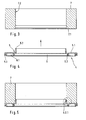
- the inner axial bend 5.2 is in accordance with the invention with the retaining lugs 5.2.1 provided, which snap into a groove 7.1 of the housing 7, so that the thrust bearing 4 is firmly attached to it.
- FIG. 7 shows further, the thrust bearing 4 in the direction of the arrow, that is, in the direction of assembly the housing 7 approximated and with the inner axial bend 5.2 inserted into the receiving bore 7.2 of the housing 7 and snapped.
- the groove 7.3 shown in FIG. 7 only differs from that in FIG. 6 by their shape. It is rectangular.
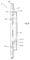
- FIG. 8 shows a further axial angle disk 8 in perspective Shown representation, which in turn has the radial section 8.2, the its inner diameter in the axial bend 8.2 and on its outer diameter passes into the axial bend 8.3.
- Both bends 8.2, 8.3 are provided with retaining lugs 8.2.1, 8.3.1, which are opposite to each other.
- the rounded design of the retaining lug 8.2.1 can be seen particularly well. This originates from point 8.2.1.1, rises in the axial direction and spreads in the circumferential direction and ends in the spaced apart Points 8.2.1.2 and 8.2.1.3. Points 8.2.1.2 and 8.2.1.3 are marked by a arcuate line connected together. In this way are holding lugs 8.2.1, 8.3.1 created a precisely defined, condensed and thus stable Have shape and have a high surface quality.
Landscapes
- Engineering & Computer Science (AREA)
- General Engineering & Computer Science (AREA)
- Mechanical Engineering (AREA)
- Rolling Contact Bearings (AREA)
Abstract
Description
- Figur 1
- einen Längsschnitt durch ein erfindungsgemäß ausgebildetes Axiallager,
- Figur 2
- eine vergrößerte Darstellung einer Einzelheit gemäß Figur 1,
- Figuren 3, 4 und 5
- die Montage eines erfindungsgemäß ausgestalteten Lagers in eine Anschlußkonstruktion,
- Figuren 6 und 7
- eine vergrößerte Darstellung einer Einzelheit aus Figur 5 und
- Figur 8
- eine perspektivische Darstellung einer erfindungsgemäß ausgebildeten Axialwinkelscheibe.
- 1
- Axiallager
- 2
- Axialwinkelscheibe
- 2.1
- Radialabschnitt
- 2.2
- axiale Abwinkelung
- 2.2.1
- Haltenase
- 3
- Axialnadelkranz
- 3.1
- Lagernadel
- 3.2
- Käfig
- 3.2.1
- radialer Flansch
- 4
- Axiallager
- 5
- Axialwinkelscheibe
- 5.1
- Radialabschnitt
- 5.2
- axiale Abwinkelung
- 5.2.1
- Haltenase
- 5.3
- axiale Abwinkelung
- 6
- Axialnadelkranz
- 6.1
- Lagernadel
- 6.2
- Käfig
- 7
- Gehäuse
- 7.1
- Nut
- 7.2
- Aufnahmebohrung
- 7.3
- Nut
- 8
- Axialwinkelscheibe
- 8.1
- Radialabschnitt
- 8.2
- axiale Abwinkelung
- 8.2.1
- Haltenase
- 8.2.1.1
- Punkt
- 8.2.1.2
- Punkt
- 8.2.1.3
- Punkt
- 8.3
- axiale Abwinkelung
- 8.3.1
- Haltenase
- s
- Nasenhöhe
- b
- Wandstärke
Claims (6)
- Einteilig ausgebildete Axialwinkelscheibe, insbesondere für ein Axiallager, mit einem eine Laufbahn bildenden Radialabschnitt, an den sich zumindest eine axiale Abwinkelung anschließt, die an wenigstens einer Umfangsstelle mit einer radial hervorspringenden Haltenase versehen ist, welche ein zugehöriges Bauteil hintergreift, so daß eine aus Axialwinkelscheibe und Bauteil bestehende unverlierbare Baueinheit gebildet ist und/oder welche in eine zugehörige Ausnehmung einer Anschlußkonstruktion eingreift, so daß eine aus Axialwinkelscheibe und Anschlußkonstruktion bestehende unverlierbare Baueinheit gebildet ist, wobei die Haltenase in Montagerichtung einen unter einem Winkel ansteigenden Verlauf nimmt und an ihrem Ende eine in radialer Richtung abfallende Anlaufkante aufweist, dadurch gekennzeichnet, daß die Haltenase (2.2.1, 5.2.1, 8.2.1, 8.3.1) mit Hilfe einer Anprägung derart hergestellt ist, daß ein nicht unterbrochener Materialzusammenhang zwischen Abwinkelung (2.2, 5.2, 8.2, 8.3) und Haltenase (2.2.1, 5.2.1, 8.2.1, 8.3.1) realisiert ist, wobei die sich in radialer Richtung erstreckende Nasenhöhe einen maximalen Betrag s von 2/3 der Wandstärke b der axialen Abwinkelung (2.2, 5.2, 8.2, 8.3) annimmt und die Haltenase (2.2.1, 5.2.1, 8.2.1, 8.3.1) in verrundeter Form ausgebildet ist.
- Axialwinkelscheibe (2) nach Anspruch 1, dadurch gekennzeichnet, daß die axiale Abwinkelung (2.2) am äußeren peripheren Ende des Radialabschnittes (2.1) angeordnet ist und die Haltenase (2.2.1) einen Käfig (3.2) hintergreift, so daß ein aus Axialwinkelscheibe (2) und Käfig (3.2) bestehendes Axiallager (1) gebildet ist.
- Axialwinkelscheibe (5) nach Anspruch 1, dadurch gekennzeichnet, daß die axiale Abwinkelung (5.2) am inneren peripheren Ende des Radialabschnittes (5.1) angeordnet ist und die Haltenase (5.2.1) in eine zugehörige Ausnehmung (7.1, 7.3) eines Gehäuses (7) eingreift, so daß eine aus Axiallager (4) und Gehäuse (7) bestehende unverlierbare Baueinheit gebildet ist.
- Axialwinkelscheibe (2, 5, 8) nach Anspruch 1, dadurch gekennzeichnet, daß die Haltenase (2.2.1, 5.2.1, 8.2.1, 8.3.1) an mehreren gleichmäßig voneinander beabstandeten Umfangsstellen angeordnet ist.
- Axialwinkelscheibe (5) nach Anspruch 1, dadurch gekennzeichnet, daß die Haltenase (5.2.1) in eine umlaufende Nut (7.1, 7.3) eingreift.
- Axialwinkelscheibe (5) nach Anspruch 5, dadurch gekennzeichnet, daß die Nut (7.1, 7.3) im Längsschnitt gesehen einen rechteck- oder einen dreieckförmigen Verlauf nimmt.
Applications Claiming Priority (2)
| Application Number | Priority Date | Filing Date | Title |
|---|---|---|---|
| DE10227377 | 2002-06-20 | ||
| DE10227377A DE10227377B4 (de) | 2002-06-20 | 2002-06-20 | Axialwinkelscheibe |
Publications (2)
| Publication Number | Publication Date |
|---|---|
| EP1375939A2 true EP1375939A2 (de) | 2004-01-02 |
| EP1375939A3 EP1375939A3 (de) | 2005-08-24 |
Family
ID=29716544
Family Applications (1)
| Application Number | Title | Priority Date | Filing Date |
|---|---|---|---|
| EP03010151A Ceased EP1375939A3 (de) | 2002-06-20 | 2003-05-06 | Montage einer Axialrollerlagerbaueinheit |
Country Status (3)
| Country | Link |
|---|---|
| US (1) | US6945700B2 (de) |
| EP (1) | EP1375939A3 (de) |
| DE (1) | DE10227377B4 (de) |
Cited By (2)
| Publication number | Priority date | Publication date | Assignee | Title |
|---|---|---|---|---|
| DE102004053194A1 (de) * | 2004-11-04 | 2006-05-11 | Ina-Schaeffler Kg | Selbsthaltendes Axialwälzlager |
| CN102138017A (zh) * | 2009-04-20 | 2011-07-27 | 日本精工株式会社 | 推力滚子轴承以及该推力轴承挡圈的制造方法 |
Families Citing this family (11)
| Publication number | Priority date | Publication date | Assignee | Title |
|---|---|---|---|---|
| WO2006034785A2 (de) * | 2004-09-28 | 2006-04-06 | Schaeffler Kg | Bauteil, insbesondere axiallagerscheibe, mit einer verdrehsicherung |
| DE102005027486B4 (de) * | 2005-06-15 | 2012-04-19 | Schaeffler Technologies Gmbh & Co. Kg | Radial-Nadellager, insbesondere Nadelhülse |
| DE102008016880B4 (de) | 2008-04-02 | 2017-05-04 | Schaeffler Technologies AG & Co. KG | Axiallager mit einer Axialwinkelscheibe mit einer eine Montagesicherung darstellenden Haltezunge und Träger mit einem solchen Axiallager |
| JP5083056B2 (ja) * | 2008-06-13 | 2012-11-28 | 日本精工株式会社 | スラストころ軸受用レースの取付装置及び取付方法 |
| JP5884580B2 (ja) * | 2012-03-19 | 2016-03-15 | 株式会社ジェイテクト | スラスト針状ころ軸受装置 |
| DE102015211304A1 (de) * | 2014-06-24 | 2015-12-24 | Schaeffler Technologies AG & Co. KG | Bauelement |
| DE102015201487A1 (de) * | 2015-01-29 | 2016-04-21 | Schaeffler Technologies AG & Co. KG | Zweireihiges Axialnadellager |
| DE102015201485A1 (de) * | 2015-01-29 | 2016-04-21 | Schaeffler Technologies AG & Co. KG | Zweireihiges Axialnadellager |
| DE102016210696B3 (de) * | 2016-06-15 | 2017-11-23 | Schaeffler Technologies AG & Co. KG | Axialwinkelscheibe |
| DE102018115182B4 (de) * | 2018-06-25 | 2023-02-23 | Schaeffler Technologies AG & Co. KG | Axialwälzlager |
| US11319994B2 (en) * | 2019-11-21 | 2022-05-03 | Jtekt Corporation | Thrust roller bearing |
Citations (1)
| Publication number | Priority date | Publication date | Assignee | Title |
|---|---|---|---|---|
| DE2264117A1 (de) | 1971-12-30 | 1973-07-12 | Torrington Co | Waelzlagerlaufring, damit gebildetes waelzlager und verfahren zum herstellen des waelzlagerlaufrings |
Family Cites Families (12)
| Publication number | Priority date | Publication date | Assignee | Title |
|---|---|---|---|---|
| US3999816A (en) * | 1971-09-21 | 1976-12-28 | Nadella | Race plate for a thrust needle or roller bearing |
| IT1031388B (it) * | 1974-02-25 | 1979-04-30 | Pitner Alfred | Reggispinta ad elementi di rotolamento cilindrici |
| US4783183A (en) * | 1987-12-28 | 1988-11-08 | The Torrington Company | Thrust bearing assembly |
| USRE34813E (en) * | 1987-12-28 | 1994-12-27 | The Torrington Company | Thrust bearing assembly |
| DE3935633C2 (de) * | 1989-10-26 | 1995-05-04 | Schaeffler Waelzlager Kg | Axialwälzlager |
| US5110223A (en) * | 1990-03-27 | 1992-05-05 | Ina Bearing Company, Inc. | Shim thrust bearing apparatus |
| DE9214980U1 (de) * | 1992-11-04 | 1992-12-24 | Skf Gmbh, 97421 Schweinfurt | Wälzlager mit Impulsring für ABS-Systeme |
| US5647675A (en) * | 1993-07-17 | 1997-07-15 | Ina Walzlager Schaeffler Kg | Angular thrust disc |
| DE9310708U1 (de) * | 1993-07-17 | 1993-09-02 | INA Wälzlager Schaeffler KG, 91074 Herzogenaurach | Axialwinkelscheibe |
| JP3316307B2 (ja) * | 1994-06-07 | 2002-08-19 | 日本トムソン株式会社 | スラスト軸受 |
| DE19542600C2 (de) * | 1995-11-15 | 2003-05-08 | Ina Schaeffler Kg | Formschlüssige Verbindung von zwei Teilen |
| JPH11336751A (ja) * | 1998-05-25 | 1999-12-07 | Ntn Corp | スラストころ軸受およびその保持器 |
-
2002
- 2002-06-20 DE DE10227377A patent/DE10227377B4/de not_active Expired - Lifetime
-
2003
- 2003-05-06 EP EP03010151A patent/EP1375939A3/de not_active Ceased
- 2003-06-20 US US10/600,486 patent/US6945700B2/en not_active Expired - Lifetime
Patent Citations (1)
| Publication number | Priority date | Publication date | Assignee | Title |
|---|---|---|---|---|
| DE2264117A1 (de) | 1971-12-30 | 1973-07-12 | Torrington Co | Waelzlagerlaufring, damit gebildetes waelzlager und verfahren zum herstellen des waelzlagerlaufrings |
Cited By (3)
| Publication number | Priority date | Publication date | Assignee | Title |
|---|---|---|---|---|
| DE102004053194A1 (de) * | 2004-11-04 | 2006-05-11 | Ina-Schaeffler Kg | Selbsthaltendes Axialwälzlager |
| CN102138017A (zh) * | 2009-04-20 | 2011-07-27 | 日本精工株式会社 | 推力滚子轴承以及该推力轴承挡圈的制造方法 |
| CN102138017B (zh) * | 2009-04-20 | 2014-02-26 | 日本精工株式会社 | 推力滚子轴承以及该推力轴承挡圈的制造方法 |
Also Published As
| Publication number | Publication date |
|---|---|
| US20040105604A1 (en) | 2004-06-03 |
| DE10227377B4 (de) | 2004-11-11 |
| US6945700B2 (en) | 2005-09-20 |
| EP1375939A3 (de) | 2005-08-24 |
| DE10227377A1 (de) | 2004-01-15 |
Similar Documents
| Publication | Publication Date | Title |
|---|---|---|
| EP1419319B2 (de) | Selbstlochendes, verdreh- und auspresssicher in ein blech einpressbares befestigungselement. | |
| EP2063136B1 (de) | Verbindungselement mit einer Schraube und einer daran unverlierbar angeordneten Hülse | |
| EP1228331B1 (de) | Anschlussarmatur für umfangsgerippte längliche körper mit einem einrastenden haltevorsprung | |
| DE10100465B4 (de) | Kugellager-Halteteil | |
| EP0726400A1 (de) | Befestigungselement aus Kunststoff | |
| DE10227377B4 (de) | Axialwinkelscheibe | |
| DE69614622T2 (de) | Rohrkupplung | |
| EP4095396B1 (de) | Toleranzausgleichsvorrichtung | |
| DE3137836A1 (de) | Lastverteilende zwischenlegscheibe zur verwendung bei zusammendrueckbarem material | |
| EP2032864B1 (de) | Scheibe und damit versehene schraubenverbindung | |
| DE3542055A1 (de) | Kugellagerkaefig | |
| WO1999030048A1 (de) | Nadellagerkäfig und verfahren zu seiner herstellung | |
| WO2019091945A1 (de) | Verliersicherung für schrauben und montageeinheit | |
| EP0171745A1 (de) | Aus einem Kunststoffspreizdübel und einer Befestigungsschraube bestehender Befestigungssatz | |
| DE102007042034A1 (de) | Befestigungssystem zum Befestigen von Bauelementen, insbesondere für Kraftfahrzeuge | |
| EP1945936A1 (de) | Dichtscheibe, insbesondere zum abdichten eines kraftstoffinjektors gegenüber einem motorblock, sowie kraftstoffinjektor | |
| WO2024126088A1 (de) | Spreizverbinder und verbindung zweier bauteile mit dem spreizverbinder | |
| WO2011003394A1 (de) | Käfig für ein kugellager und verfahren zur herstellung des käfigs | |
| DE102005027486B4 (de) | Radial-Nadellager, insbesondere Nadelhülse | |
| DE102017223636A1 (de) | Montageeinheit sowie Fixierhülse für eine solche Montageeinheit | |
| DE20016150U1 (de) | Vorrichtung zum Verbinden von Bauteilen | |
| DE2443366A1 (de) | Sicherungselement fuer grosse waelzlager und waelzlagerteile | |
| DE102017126037A1 (de) | Spreizdübel | |
| DE102022133218A1 (de) | Spreizverbinder und Verbindung zweier Bauteile mit dem Spreizverbinder | |
| DE102013113993A1 (de) | Montageeinheit |
Legal Events
| Date | Code | Title | Description |
|---|---|---|---|
| PUAI | Public reference made under article 153(3) epc to a published international application that has entered the european phase |
Free format text: ORIGINAL CODE: 0009012 |
|
| 17P | Request for examination filed |
Effective date: 20030506 |
|
| AK | Designated contracting states |
Kind code of ref document: A2 Designated state(s): AT BE BG CH CY CZ DE DK EE ES FI FR GB GR HU IE IT LI LU MC NL PT RO SE SI SK TR |
|
| AX | Request for extension of the european patent |
Extension state: AL LT LV MK |
|
| PUAL | Search report despatched |
Free format text: ORIGINAL CODE: 0009013 |
|
| AK | Designated contracting states |
Kind code of ref document: A3 Designated state(s): AT BE BG CH CY CZ DE DK EE ES FI FR GB GR HU IE IT LI LU MC NL PT RO SE SI SK TR |
|
| AX | Request for extension of the european patent |
Extension state: AL LT LV MK |
|
| RAP1 | Party data changed (applicant data changed or rights of an application transferred) |
Owner name: SCHAEFFLER KG |
|
| AKX | Designation fees paid |
Designated state(s): CZ DE FR GB IT |
|
| 17Q | First examination report despatched |
Effective date: 20060712 |
|
| STAA | Information on the status of an ep patent application or granted ep patent |
Free format text: STATUS: THE APPLICATION HAS BEEN REFUSED |
|
| 18R | Application refused |
Effective date: 20090131 |
|
| P01 | Opt-out of the competence of the unified patent court (upc) registered |
Effective date: 20230523 |