EP1375729A2 - Support, en particulier séchoir à linge - Google Patents
Support, en particulier séchoir à linge Download PDFInfo
- Publication number
- EP1375729A2 EP1375729A2 EP03010229A EP03010229A EP1375729A2 EP 1375729 A2 EP1375729 A2 EP 1375729A2 EP 03010229 A EP03010229 A EP 03010229A EP 03010229 A EP03010229 A EP 03010229A EP 1375729 A2 EP1375729 A2 EP 1375729A2
- Authority
- EP
- European Patent Office
- Prior art keywords
- stand
- holding
- particular according
- rods
- stand according
- Prior art date
- Legal status (The legal status is an assumption and is not a legal conclusion. Google has not performed a legal analysis and makes no representation as to the accuracy of the status listed.)
- Withdrawn
Links
- 238000001035 drying Methods 0.000 title description 2
- 239000000725 suspension Substances 0.000 claims description 28
- 238000003780 insertion Methods 0.000 claims 1
- 230000037431 insertion Effects 0.000 claims 1
- 230000002093 peripheral effect Effects 0.000 description 3
- 238000006073 displacement reaction Methods 0.000 description 2
- NJPPVKZQTLUDBO-UHFFFAOYSA-N novaluron Chemical compound C1=C(Cl)C(OC(F)(F)C(OC(F)(F)F)F)=CC=C1NC(=O)NC(=O)C1=C(F)C=CC=C1F NJPPVKZQTLUDBO-UHFFFAOYSA-N 0.000 description 2
- 230000000717 retained effect Effects 0.000 description 2
- 239000011343 solid material Substances 0.000 description 2
- 230000001360 synchronised effect Effects 0.000 description 2
- 230000004308 accommodation Effects 0.000 description 1
- 230000009286 beneficial effect Effects 0.000 description 1
- 230000015572 biosynthetic process Effects 0.000 description 1
- POIUWJQBRNEFGX-XAMSXPGMSA-N cathelicidin Chemical compound C([C@@H](C(=O)N[C@@H](CCCNC(N)=N)C(=O)N[C@@H](CCCCN)C(=O)N[C@@H](CO)C(=O)N[C@@H](CCCCN)C(=O)N[C@@H](CCC(O)=O)C(=O)N[C@@H](CCCCN)C(=O)N[C@@H]([C@@H](C)CC)C(=O)NCC(=O)N[C@@H](CCCCN)C(=O)N[C@@H](CCC(O)=O)C(=O)N[C@@H](CC=1C=CC=CC=1)C(=O)N[C@@H](CCCCN)C(=O)N[C@@H](CCCNC(N)=N)C(=O)N[C@@H]([C@@H](C)CC)C(=O)N[C@@H](C(C)C)C(=O)N[C@@H](CCC(N)=O)C(=O)N[C@@H](CCCNC(N)=N)C(=O)N[C@@H]([C@@H](C)CC)C(=O)N[C@@H](CCCCN)C(=O)N[C@@H](CC(O)=O)C(=O)N[C@@H](CC=1C=CC=CC=1)C(=O)N[C@@H](CC(C)C)C(=O)N[C@@H](CCCNC(N)=N)C(=O)N[C@@H](CC(N)=O)C(=O)N[C@@H](CC(C)C)C(=O)N[C@@H](C(C)C)C(=O)N1[C@@H](CCC1)C(=O)N[C@@H](CCCNC(N)=N)C(=O)N[C@@H]([C@@H](C)O)C(=O)N[C@@H](CCC(O)=O)C(=O)N[C@@H](CO)C(O)=O)NC(=O)[C@H](CC=1C=CC=CC=1)NC(=O)[C@H](CC(O)=O)NC(=O)CNC(=O)[C@H](CC(C)C)NC(=O)[C@@H](N)CC(C)C)C1=CC=CC=C1 POIUWJQBRNEFGX-XAMSXPGMSA-N 0.000 description 1
- 238000005253 cladding Methods 0.000 description 1
- 230000000295 complement effect Effects 0.000 description 1
- 238000010276 construction Methods 0.000 description 1
- 238000005553 drilling Methods 0.000 description 1
- 230000000694 effects Effects 0.000 description 1
- 230000002349 favourable effect Effects 0.000 description 1
- 239000011521 glass Substances 0.000 description 1
- 230000006698 induction Effects 0.000 description 1
- 230000003993 interaction Effects 0.000 description 1
- 235000013372 meat Nutrition 0.000 description 1
- 239000002184 metal Substances 0.000 description 1
- 238000000034 method Methods 0.000 description 1
- 230000000284 resting effect Effects 0.000 description 1
- 210000002435 tendon Anatomy 0.000 description 1
- 239000004753 textile Substances 0.000 description 1
- 238000005406 washing Methods 0.000 description 1
Images


Classifications
-
- D—TEXTILES; PAPER
- D06—TREATMENT OF TEXTILES OR THE LIKE; LAUNDERING; FLEXIBLE MATERIALS NOT OTHERWISE PROVIDED FOR
- D06F—LAUNDERING, DRYING, IRONING, PRESSING OR FOLDING TEXTILE ARTICLES
- D06F57/00—Supporting means, other than simple clothes-lines, for linen or garments to be dried or aired
- D06F57/08—Folding stands
Definitions
- the invention relates to a collapsible, freely erectable Stands, especially clothes racks, with hinged hinged Holding rods and the holding rods transversely connecting suspension rods, the Holding rods considered in terms of their upper ends, from a Storage collapsed position in a use-distance position can be distanced from one another, further feet being formed on the base side are and the holding rods at the bottom without crossing in one with each a support area connected to a base converge.
- a clothes horse with advanced scissor rack function is from the Pro • Idea catalog, known in 2002.
- the support rods are on the front there Sections of a pair of Nuremberg scissors, of which middle sections are in Complement crossing feet on the bottom. The sections and the The feet are connected to each other over several days using suspension rods.
- a clothes horse according to the features of the preamble of Claim 1 results from FR-2 360 707.
- the hinged Articulated support rods are connected to a U-bracket via a suspension rod designed.
- the ends of the holding rods facing the stand have meandering offsets. Cross sections of it limit the horizontal use distance here.
- the Articulation points are offset in the vertical direction of the stand.
- the Articulation of the support rods is such that they are spaced in two Floors are grouped and still vertically offset in terms of articulation converge.
- Bottom feet of the stand can be in the Meaning of a space-saving storage collapsible position in the Essentially in the plane of the U-shaped stand Valves.
- the folding position of the holding rods is secured by a hook.
- GB 2 272 635 A proposes a washing line as well hanging clothes rack with hinged hinged support bars to provide. But they are across a bar in the articulation area connected.
- the holding rods extend from the strips like stakes. Your upper, free ends can be fitted with hollow textiles, e.g. socks.
- the middle holding rods are firmly held in the U-shaped stand.
- the feet can be cantilevered on the bottom side according to a basic version pull out and push back into the mounting area to save space.
- the object of the invention is a collapsible, freely erectable Stands, especially clothes horse, structurally simple, advantageous in handling as well as training to dry.
- At least one holding rod is in the use distance position of the Stands oriented on a vertical. It forms, as it were Two-column stand on which the holding rods fold down or on which they fold in a defined position. Added to this is the advantage that this holding rod practically the same hanging ability is achieved as with the foldable Holding bars and hanging bars. It is also advantageous if a middle support bar in the use spacing oriented on the vertical runs. This results in a hanging area that is balanced on both sides.
- an advantageous feature of the invention is that the Bracket area is formed by a bearing plate with which the Holding rods are articulated on the foot side.
- the plate shape allows one row-shaped linkage of the crossover-free connection.
- a stand advantageously consists of two opposite Stand-sections.
- the intermediate field of the counterpart may be too Control purposes. Accordingly, it turns out training as favorable that the base sections by a assigned transverse clip connected to their respective free end regions are secured in the folding direction.
- the cross bar extends like one String into an arch, the arch through the stand sections is provided. This is the cross bar practically formed by control rods split formed with a central division joint. At the division joint then attacks the foot of a support bar.
- the corresponding sliding bearing is vertical oriented.
- This holding bar cannot be folded down. He poses as if Double column the central U-shaped unit holding rods / suspension rod. It then follow the others outwards on the bearing plate Units of support rods / suspension rods. Their exhibition in the Use distance is defined by simple means. So that brings Invention proposed that the use spacing of the support rods is secured by connection. To this end, the procedure is such that the Holding rods above the mounting area in the opening direction Bounding elements are connected to limit the maximum Aufklappweite. The stretching position of the limiting elements is determined by the resulting weight of a support rod is reached.
- the pedestal sections are interconnected by cross bars are connected.
- Such trusses stabilize the underfloor area of the Stand and also guarantee synchronous folding movements of the Stand sections when indicated switching to one or the other Functional position of the stand.
- the pedestal sections are hinged to the bearing plate so that they can be folded down are with regard to a vertical extension of the stand size of the stand when folded.
- the adjustment dimension is chosen so that the holding rods connected to the crossbar on the foot side collapsed state on the head side of the adjacent support rods each surmounted. So the associated hanging bar is cantilevered. On one Graspable overhang is of course noted.
- Such a graspable Surplus can also be independent of the collation of the Feet can be realized simply by a corresponding vertical Excess length, in any case in the folded position a hanging bar is arranged higher than other suspension rods.
- the higher is expedient arranged suspension rod with the sliding in the bearing plate Holding rod connected.
- To the holding rods in the collapsed position of the Securing the stand against unwanted folding out is one on a holding rod Retaining latch attached to the latching bracket of the other retaining rods. It can act as a simple spring finger that can evade into the Folding level of the support rods protrudes.
- the holding latch is as Retainer trained. Your resting space takes a plurality of Holding rods, whereby only the peripheral is held accordingly.
- the storage collapsible position the stand is secured in place.
- a snap-in as a die part Locking device is in any case designed for a holding rod.
- said Bearing plate has another function. It works expediently Snap-in with the slide-mounted holding rod together, since this from Offers a relocation stroke at home. So it becomes consequent proceeded that the locking receptacle, assigned to a bottom side of the Bearing plate, with the protruding foot of the sliding support rod interacts.
- the sliding support rod at right angles to the longitudinal extent of the same
- the locking pin protrudes as a male part of the locking device for driving into the a footprint vertically open latch.
- the locking pin is the counter locking means is an axially correspondingly elongated pivot pin of the dividing joint. The latter is given a more extensive function.
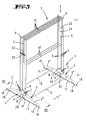
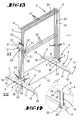
- the illustrated, usable as a clothes horse, free-standing stand S both Embodiments has an upper, staggered height Hanging area 1 and a lower setting area 2.
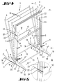
- the articulation points of the pair of feet 3 provided in the area near the floor the bearing plate 4 are designated 6. It is e.g. B. refer to Fig. 6.
- Holding rods 5 realized. There is a holding rod between these groups 5, which is not in the articulation to the bearing plate 4, but this is assigned to be vertically displaceable.
- the Bearing plate 4 takes into account a bore 8 in which the vertical displaceable, central holding rod 5 leads without tilting.
- Holding rods 5 are closed with a cap. Below the corresponding caps 9 attaches a hanging bar 10 between each pair of holding bars 5.
- the intermediate suspension rod 10 leads together with the ground-level mounting area H leading holding rods 5 to a U-bracket. Except for the middle U-bracket, everyone can be folded out like a fan. The corresponding fan is in full execution from Fig. 1 and in partial application from FIG. 4. Such U-bracket can also be the same be folded in one piece from tube or solid material.
- the unfolding movement of the holding rods 5 is due to the shield-like bearing plate 4 sided.
- a bearing trench 11 is provided in the bearing plate 4.
- the articulation points 7 of the holding rods 5 can be seen as close as possible the Lagergrabenground 12. Since the parallel trench walls clearly follow Continue above the relevant articulation area and the width of the Bearing trench 11 is matched to the outer diameter of the holding rods 5, there is a transverse tilting in the axial direction of the articulation points 7 avoiding, rich guide system on the trench walls. It is on Fig. 8 directed.
- the same principle is applied to the feet 3.
- the relevant tunnel which is open to a footprint 13 of the stand S, is included Designated 14.
- the stand sections 3 ', 3 are good on the tunnel walls led to.
- the tunnel ceiling secures the arc of the same to each other. Foldability is taken into account, simply by sufficient Frontal rounding of the vertical longitudinal center plane x of the stand S facing end of the sections 3 ', 3 ".
- the base sections 3 ′, 3 ′′ are furthermore formed by cross bars 15 connected with each other.
- the crossbar-like cross bars 15 set approximately in Region of the longitudinal center of said sections 3 'or 3 ". It can be about act a welded joint.
- the displacement stroke of the central holding rod 5 is as an encoder or Control means for the space-saving folding of the Stand sections 3 ', 3 "are used.
- the paired holding rod 5 extended like a foot beyond the underside of the bearing plate 4.
- This Base of the central holding rod 5 bears the reference number 16. It passes the described tunnel 14. There is enough passage between the two spaced joints 6 instead.
- the lower, free end of the foot 16 engages with respect to the arcuate feet 3 tendon-like control linkage, which itself extends just above the footprint 13 of the stand S. It is concrete with respect to the control linkage around a crossbar 17.
- the free ends the transverse clasp 17 are articulated at 19 with the end region of the Stand sections 3 ', 3 "connected. These free end portions of the sections 3 ', 3 "are equipped with a cap 18, forming an anti-slip device Stands S.
- the hinge points 19 of the respective end regions extend in Folding direction of the feet 3, or their sections 3 ', 3 ", so underside of the same.
- the transverse clasp 17 becomes Folding down or partially folding the stand sections 3 ', 3 "over the foot 16 by means of the central holding rod 5 in the direction of Bracket area H pulled.
- the cross clasp 17 is in two parts educated. The attack of foot 16 or on the ground is consequent free end of the same via a dividing joint 20 instead.
- the folding actuation the sections 3 ', 3 " is synchronous with respect to both ends of the stand S. exercisable, simply due to the fact that the central holding rod 5 -like already indicated above in pairs, i.e. also as easy to handle U-bracket is designed.
- the direction of pull on the controlling U-bracket is also indicated by arrows indicated.
- the fold-out holding rods 5 are above the holding area H in Opening direction arrow z connected by limiting elements 22.
- the stretching position of the limiting elements 22 has already been reached by the resulting weight of a holding rod 5 or the entire U-bracket.
- the limiting elements 22 are from across the entire end face of the stator S. trending chains formed. The fixation can be done by screwing happen.
- a second floor of the hanging can be horizontal, lower lying Suspension rods 10 'can be reached. Because of the towards the center A U-bracket with regard to staffing is becoming increasingly close roll over.
- the base sections 3 ', 3 "on the bearing plate 4 can be seen in this way hinged at the bottom that folds up in a space-saving way Condition of the stand S extended vertically upwards.
- the stand S according to the second embodiment is basically the same construction; the reference numbers are used analogously, some without textual repetitions.
- the holding rod 5, which is mounted in a sliding manner in the bearing plate 4, is not merely related of its exposed grip position, but also in the sense a fastening base for securing the holding rods 5 in the folding position.
- This is embodied in the design and assignment of a holding branch 26.
- To Plug-in assignment of the holding peg 26 has a central, vertical, cylindrical opening 27 on. Their clear diameter corresponds to that Outside diameter of the inserted holding rod 5.
- the Retaining peg 26 is used for a horizontal, diametrically transverse opening 27 Bore 28.
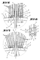
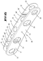
- the holding latch 26 is designed in the form of a retaining clip. That is what Following the pivoting curve of the articulated holding rods 5, essentially curved around the articulation points 7. Reference is made to FIG. 16.
- the top view shown in FIG. 17 makes it clear that the retaining clip has the shape of an H-profile. This extends in the area of the H-bridge Meat circumscribing the vertical opening 27. Of this Area 30 go out in opposite directions, limited by parallel the fork-shaped H-legs of the holding peg 26.
- the H-legs form resilient locking fingers 31. Inside sit on them Retaining tabs 26 '. The direct distance between two such Retaining tabs 26 'is smaller than the outer diameter of the holding rods 5. The standing height of the retaining lugs 26 ', on the other hand, is such that they pass through will-like folding of the articulated holding rods 5 like a snap can be overcome.
- the length of the locking spaces 30 of the holding latch 26 is such that a A plurality, here three holding rods 5 are accommodated therein in cross-section.
- the fork-like locking fingers 31 sit under formation a catch opening 32 to the outside.
- the horizontal room length of this practically a vestibule opening 32 corresponds to that in the Horizontal measured length of the room 30.
- the length of the room 30 is shorter than the effective length of a limiting element 22.
- the locking fingers 31 are broken through like a window.
- the corresponding Perforation is particularly clear from Fig. 15.
- the windows are 33 designated.
- the effect of the holding bracket 26 is given even if per Side only a locking finger 31 is realized because the articulated in the bearing plate 4 Holding rods 5 are guided by the trenches 11 there.
- the orderly alignment is also present at the height of the holding branch 26.
- the resilient retaining clip that is to say holding bracket 26, can be made of metal be or also made of plastic.
- peripheral holding rods can be unlatched, for example become; the rest are retained via the retaining tabs 26 '.
- the exhibition of the entire group of three on holding rods 5 is shown in FIG. 21 removable.
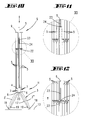
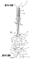
- a third training in connection with the central, vertical slide bearing support rod 5 consists in the interaction with a locking device, which the storage collapsed position of the Stand S maintained. It is also necessary to form this detent Bearing plate 4 involved.
- the position in question clearly results from Fig. 19. In this position the articulated feet 3, more precisely the Sections 3 ', 3 "leaving stability, folded together.
- the bearing plate 4 provides the die part of the said locking device a snap-in receptacle 34. This is vertically open towards the footprint 13. spatial it extends in the longitudinal central plane x-x of the stand S, in which the runs down into a foot 16, central holding rod 5, in effective proximity to the catch 34.
- the locking receptacle 34 is located on the bottom side of the bearing plate 4.
- the Surrounding recording 34 circumscribing environment dominates this lower bottom of the Bearing plate 4 recognizable.
- the design is such that two resilient Protrude 35.
- the actual receiving cavity of the latching receptacle 34 is horizontal running bore, the opening of which starts beyond the equator and in Einlenkflanken 35 merges, forming a catch funnel for the Securing means.
- the counter-locking means is the male part of the locking device a locking pin 36.
- The is perpendicular to the longitudinal extension of the sliding support rod 5 or his foot 16.
- the protrudes Locking pin 36 in the effective range of the fixed locking receptacle 34 is sufficient for safe entry into the locking receptacle 34.
- the locking pin is cylindrical shape, adapted to the dimension of the locking receptacle 34 forming Drilling. Relief is given with will.
- Such a locking receptacle 34 can also be on the inside of the bearing plate 4 be realized, as well as the locking device at the other end of the stand can sit or can be additionally provided there.
- Such a measure is conceivable for long stands S. To length one To enable downsizing, the horizontal components 10, 10 ', 15 be designed telescopic.
- a particularly advantageous embodiment of the training of the described Locking protection consists in the locking pin 36 providing the counter locking means is an axially correspondingly elongated pivot pin of the division joint 20.
- the induction of the locking between the locking receptacle 34 and the Locking pin 36 happens automatically by pulling the middle U-bracket, consisting of the middle holding rods 5 and the free-standing one Pull handle available hanging bar 10. The position is 19 before.
Landscapes
- Engineering & Computer Science (AREA)
- Textile Engineering (AREA)
- Holders For Apparel And Elements Relating To Apparel (AREA)
- Drying Of Solid Materials (AREA)
Applications Claiming Priority (2)
| Application Number | Priority Date | Filing Date | Title |
|---|---|---|---|
| DE2002126938 DE10226938A1 (de) | 2002-06-17 | 2002-06-17 | Ständer, insbesondere Wäscheständer |
| DE10226938 | 2002-06-17 |
Publications (2)
| Publication Number | Publication Date |
|---|---|
| EP1375729A2 true EP1375729A2 (fr) | 2004-01-02 |
| EP1375729A3 EP1375729A3 (fr) | 2004-03-17 |
Family
ID=29594584
Family Applications (1)
| Application Number | Title | Priority Date | Filing Date |
|---|---|---|---|
| EP03010229A Withdrawn EP1375729A3 (fr) | 2002-06-17 | 2003-05-07 | Support, en particulier séchoir à linge |
Country Status (2)
| Country | Link |
|---|---|
| EP (1) | EP1375729A3 (fr) |
| DE (1) | DE10226938A1 (fr) |
Families Citing this family (1)
| Publication number | Priority date | Publication date | Assignee | Title |
|---|---|---|---|---|
| DE102005061622A1 (de) * | 2005-12-21 | 2007-07-05 | Leifheit Ag | Wäschetrockner |
Citations (4)
| Publication number | Priority date | Publication date | Assignee | Title |
|---|---|---|---|---|
| DE158528C (fr) | ||||
| DE2430083A1 (de) | 1974-06-22 | 1976-01-08 | Muenkel Kg Karl | Scheren-waeschetrockner |
| FR2360707A1 (fr) | 1976-06-25 | 1978-03-03 | Ducros Georges | Support de linge repasse ou a repasser |
| GB2272635A (en) | 1992-11-20 | 1994-05-25 | Philip Harcourt Coe | Portable drying aid for clothing |
Family Cites Families (6)
| Publication number | Priority date | Publication date | Assignee | Title |
|---|---|---|---|---|
| US2353374A (en) * | 1943-03-17 | 1944-07-11 | John S Thompson | Clothes drier |
| IT208704Z2 (it) * | 1986-11-19 | 1988-05-28 | Siro Spa | Stendi-biancheria domestico corredato di vaschetta porta-mollette,i cui bracci articolati a ventaglio sono collegati da aste snodate in mezzeria a mo' di ginocchio |
| JP3232504B2 (ja) * | 1996-09-06 | 2001-11-26 | 貞雄 中野 | 開脚アジャスター付折畳式物干器 |
| DE19906534B4 (de) * | 1999-02-17 | 2007-11-15 | Carl Freudenberg Kg | Gelenk für einen Wäschetrockner |
| JP4271305B2 (ja) * | 1999-07-23 | 2009-06-03 | アイリスオーヤマ株式会社 | 物干台 |
| JP2003053099A (ja) * | 2001-08-20 | 2003-02-25 | Sekisui Jushi Co Ltd | 物干し台 |
-
2002
- 2002-06-17 DE DE2002126938 patent/DE10226938A1/de not_active Withdrawn
-
2003
- 2003-05-07 EP EP03010229A patent/EP1375729A3/fr not_active Withdrawn
Patent Citations (4)
| Publication number | Priority date | Publication date | Assignee | Title |
|---|---|---|---|---|
| DE158528C (fr) | ||||
| DE2430083A1 (de) | 1974-06-22 | 1976-01-08 | Muenkel Kg Karl | Scheren-waeschetrockner |
| FR2360707A1 (fr) | 1976-06-25 | 1978-03-03 | Ducros Georges | Support de linge repasse ou a repasser |
| GB2272635A (en) | 1992-11-20 | 1994-05-25 | Philip Harcourt Coe | Portable drying aid for clothing |
Also Published As
| Publication number | Publication date |
|---|---|
| EP1375729A3 (fr) | 2004-03-17 |
| DE10226938A1 (de) | 2003-12-24 |
Similar Documents
| Publication | Publication Date | Title |
|---|---|---|
| EP0486428B1 (fr) | Bras à vêtements pour suspendre les vêtements | |
| DE60212335T2 (de) | Klapprahmenkonstruktion | |
| DE3830456C2 (fr) | ||
| DE212018000247U1 (de) | Seitlich tragendes Fahrzeug-Dachzelt | |
| DE8908193U1 (de) | Schwenkbarer Mehrfachkleiderbügel mit Führungsschiene | |
| EP0181584A2 (fr) | Présentoir pour vêtements avec colonnes polygonales réglables en hauteur | |
| EP1375729A2 (fr) | Support, en particulier séchoir à linge | |
| EP1627948A1 (fr) | Séchoir à linge | |
| EP1331301B1 (fr) | Séchoir à linge pliable | |
| DE4437200A1 (de) | Instrumentenständer, insbesondere für Gitarren | |
| WO1990009130A1 (fr) | Cintre | |
| DE202021100420U1 (de) | Wäschetrocknungsgestell | |
| DE1460827A1 (de) | Waeschetrockner | |
| DE1434946A1 (de) | Ausziehbare Tragkonstruktion | |
| EP0213280B1 (fr) | Séchoir à linge extensible | |
| DE10046687A1 (de) | Wäschetrockengestell | |
| DE20314289U1 (de) | Tisch mit Mehrfachfunktion | |
| WO2006018075A1 (fr) | Sechoir a linge | |
| DE102006054950B3 (de) | Zusammenklappbares Standgestell für einen Bügeltisch | |
| DE20304655U1 (de) | Zusammenklappbarer Trockenständer | |
| DE29601539U1 (de) | Klappbarer Wäschetrockner | |
| CH685302A5 (de) | Ausziehbarer Wäschetrockner. | |
| DE8505519U1 (de) | Regal, insbesondere zur stapelbaren Lagerung von Brennholz | |
| WO2008052779A1 (fr) | Élément de recouvrement d'une garniture de table et ensemble avec un élément de recouvrement et au moins une table | |
| EP0488929A1 (fr) | Dispositif pour suspendre le linge, en particulier pour le sécher |
Legal Events
| Date | Code | Title | Description |
|---|---|---|---|
| PUAI | Public reference made under article 153(3) epc to a published international application that has entered the european phase |
Free format text: ORIGINAL CODE: 0009012 |
|
| AK | Designated contracting states |
Kind code of ref document: A2 Designated state(s): AT BE BG CH CY CZ DE DK EE ES FI FR GB GR HU IE IT LI LU MC NL PT RO SE SI SK TR |
|
| AX | Request for extension of the european patent |
Extension state: AL LT LV MK |
|
| PUAL | Search report despatched |
Free format text: ORIGINAL CODE: 0009013 |
|
| AK | Designated contracting states |
Kind code of ref document: A3 Designated state(s): AT BE BG CH CY CZ DE DK EE ES FI FR GB GR HU IE IT LI LU MC NL PT RO SE SI SK TR |
|
| AX | Request for extension of the european patent |
Extension state: AL LT LV MK |
|
| AKX | Designation fees paid | ||
| REG | Reference to a national code |
Ref country code: DE Ref legal event code: 8566 |
|
| STAA | Information on the status of an ep patent application or granted ep patent |
Free format text: STATUS: THE APPLICATION IS DEEMED TO BE WITHDRAWN |
|
| 18D | Application deemed to be withdrawn |
Effective date: 20040918 |