EP1375080A2 - Machine-outil avec un mécanisme de blocage pour bloquer son arbre d'entraínement - Google Patents
Machine-outil avec un mécanisme de blocage pour bloquer son arbre d'entraínement Download PDFInfo
- Publication number
- EP1375080A2 EP1375080A2 EP03006698A EP03006698A EP1375080A2 EP 1375080 A2 EP1375080 A2 EP 1375080A2 EP 03006698 A EP03006698 A EP 03006698A EP 03006698 A EP03006698 A EP 03006698A EP 1375080 A2 EP1375080 A2 EP 1375080A2
- Authority
- EP
- European Patent Office
- Prior art keywords
- blocking
- drive shaft
- rotation
- machine tool
- lever
- Prior art date
- Legal status (The legal status is an assumption and is not a legal conclusion. Google has not performed a legal analysis and makes no representation as to the accuracy of the status listed.)
- Granted
Links
Images

Classifications
-
- B—PERFORMING OPERATIONS; TRANSPORTING
- B25—HAND TOOLS; PORTABLE POWER-DRIVEN TOOLS; MANIPULATORS
- B25F—COMBINATION OR MULTI-PURPOSE TOOLS NOT OTHERWISE PROVIDED FOR; DETAILS OR COMPONENTS OF PORTABLE POWER-DRIVEN TOOLS NOT PARTICULARLY RELATED TO THE OPERATIONS PERFORMED AND NOT OTHERWISE PROVIDED FOR
- B25F5/00—Details or components of portable power-driven tools not particularly related to the operations performed and not otherwise provided for
- B25F5/001—Gearings, speed selectors, clutches or the like specially adapted for rotary tools
-
- B—PERFORMING OPERATIONS; TRANSPORTING
- B23—MACHINE TOOLS; METAL-WORKING NOT OTHERWISE PROVIDED FOR
- B23Q—DETAILS, COMPONENTS, OR ACCESSORIES FOR MACHINE TOOLS, e.g. ARRANGEMENTS FOR COPYING OR CONTROLLING; MACHINE TOOLS IN GENERAL CHARACTERISED BY THE CONSTRUCTION OF PARTICULAR DETAILS OR COMPONENTS; COMBINATIONS OR ASSOCIATIONS OF METAL-WORKING MACHINES, NOT DIRECTED TO A PARTICULAR RESULT
- B23Q5/00—Driving or feeding mechanisms; Control arrangements therefor
- B23Q5/02—Driving main working members
- B23Q5/04—Driving main working members rotary shafts, e.g. working-spindles
- B23Q5/20—Adjusting or stopping working-spindles in a predetermined position
-
- B—PERFORMING OPERATIONS; TRANSPORTING
- B25—HAND TOOLS; PORTABLE POWER-DRIVEN TOOLS; MANIPULATORS
- B25B—TOOLS OR BENCH DEVICES NOT OTHERWISE PROVIDED FOR, FOR FASTENING, CONNECTING, DISENGAGING OR HOLDING
- B25B15/00—Screwdrivers
- B25B15/02—Screwdrivers operated by rotating the handle
- B25B15/04—Screwdrivers operated by rotating the handle with ratchet action
-
- B—PERFORMING OPERATIONS; TRANSPORTING
- B25—HAND TOOLS; PORTABLE POWER-DRIVEN TOOLS; MANIPULATORS
- B25B—TOOLS OR BENCH DEVICES NOT OTHERWISE PROVIDED FOR, FOR FASTENING, CONNECTING, DISENGAGING OR HOLDING
- B25B21/00—Portable power-driven screw or nut setting or loosening tools; Attachments for drilling apparatus serving the same purpose
Definitions
- the invention relates to a machine tool, in particular a hand machine tool, with a motor-driven drive shaft for rotatingly driving a workpiece Machining tool and one accessible from the outside and fastening screw which can be rotated by means of a turning tool or fastening nut for the rotationally fixed connection of the processing tool with the drive shaft, the drive shaft a blocking device for blocking the drive shaft in loosening and / or tightening the fastening screw or fastening nut assigned to the corresponding direction of rotation is.
- Such blocking devices are known in many ways. With them, the drive shaft when changing the machining tool held on so that they could, for example when loosening the fastening screw or fastening nut can't turn.
- the present invention is therefore based on the object to create a machine tool of the type mentioned at the beginning, loosening and / or tightening the fastening screw or fastening nut compared to the previous constructions is relieved.
- Blocking device a rotatably connected to the drive shaft Locking gear and a locking gear assigned to the locking gear around a stationary on the machine tool Swivel axis swiveling, manually operated ratchet lever contains, the latch lever one-armed or two-armed and is out of engagement with the spring force Blocking gear is held in the initial position and against the spring force with a one-armed ratchet lever in a blocking position and with two-armed ratchet lever in two opposite blocking positions can be pivoted with the locking gear in each locking position against twisting in either loosening or tightening corresponding to the fastening screw or fastening nut Direction of rotation is blocked and in the opposite direction of rotation can rattle past the ratchet lever and where between the fastening screw or fastening nut and the drive shaft has a frictional force, so that the Drive shaft when turning the fastening screw or Fastening nut opposite in the blocked direction of rotation Direction of rotation is taken.
- the turning tool must be released and / or Tighten on the mounting screw or mounting nut not implemented, regardless of how long the rotation required for loosening and / or tightening the fastening screw or fastening nut.
- the blocking device according to the invention is in such Machine tools particularly advantageous that have a collet have for receiving the machining tool and where the fastening nut overlaps the collet Union nut is so that when tightening the union nut this the collet against the machining tool stressed.
- the thread of such a union nut has a relatively small slope, so that to Loosen and / or tighten the tension several turns required are.
- Blocking device and associated safety device has a usual structure, so that a description the other construction of the router is unnecessary.
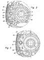
- the router has one around an axis of rotation during operation 1 rotating drive shaft 2 by a, not shown Drive motor is driven forth.
- Am from the machine housing 3 projecting end portion of the drive shaft 2 is a Inner cone 4 formed.
- a collet 5 is used, the one Inner cone 4 forms the corresponding outer cone 6.
- the collet 5 has axially directed slots 7 through which the Collet wall in, separated by the slots, strip-like elongated jaws is divided.
- a fastening nut 11 designed as a union nut is arranged.
- the mounting nut 11 has at its Conical surface 10 opposite area 12 an internal thread 13 with which they are on an external thread 14 on the drive shaft 2 is screwed on.
- the fastening nut 11 is exposed, so that it is from the outside is accessible and rotated by means of a turning tool can be.
- the turning tool can be, for example, a polygonal wrench be that of a correspondingly polygonal Outer peripheral surface of the mounting nut 11 is attached.
- a blocking device 16 is therefore assigned to the drive shaft 2, with which the drive shaft 2 can be blocked. This blocking can be done in one way or another Direction of rotation take place so that the drive shaft too can hold tight when tightening the fastening nut 11.
- the blocking device 16 contains a rotationally fixed with the Drive shaft 2 connected, arranged coaxially to the drive shaft 2 Locking gear 17, the embodiment has circumferential external teeth 18.
- the blocking gear 17 can be arranged within the machine housing 3 his.
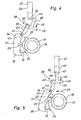
- the blocking gear 17 is a hand from the outside actuatable ratchet lever 19 assigned to a fixed arranged on the machine tool, parallel to the drive shaft 2 extending pivot axis 20 is pivotable.
- the Pawl lever 19 around a two-armed lever which extends in the circumferential direction of the gear 17 seen on both sides of the pivot axis 20 each form a lever arm 21 or 22. Every lever arm 21, 22 has on its side facing the gear 27 toothing device formed by at least one tooth or a tooth gap 23 or 24 on the teeth 18 of the Gear 17 is assigned.
- the pawl lever 19 is in its initial position, in which the two toothing devices 23, 24 lie opposite the gear 17 at a distance, so that the pawl lever 19 is disengaged from the blocking gear 17.
- the pawl lever 19 is held in this starting position by spring force.
- the ratchet lever can be released from the above-mentioned starting position 19 against the spring force in one or the other Swivel direction so that it is in two opposite to each other Blocking positions can be pivoted in which either one toothing device 23 or the other Gear device 24 with the gear 17 in gear engagement stands (in FIG. 5, the toothing device 23 engages into the gear teeth 18).
- the gear 18 against rotation in the corresponding Direction of rotation blocked from the outside against the relevant one Gear device 23.24 is directed.
- gear 17 against rotation in the direction secured according to arrow 25 In the opposite direction can gear 17, on the other hand, engages with it Gear device, in the case of FIG. 5 the gear device 23, rattle past. With this rattle past the ratchet lever slips with its relevant toothing device via the gear 17 and leads one of the teeth 18 corresponding swiveling movements out.
- the drive shaft non-rotatably connected to the gear 17 2 optionally blocked in both directions of rotation, depending on the direction in which the pawl lever 19 is pivoted. So it is in the case of the embodiment the two-armed ratchet lever 19 possible, the drive shaft 2 both when loosening and when tightening the fastening nut 11 to block.
- a frictional force is effective, so that the drive shaft 2 when turning the fastening nut 11 by means of the turning tool in the opposite direction of the blocked direction of rotation Direction of rotation is taken.
- a driving friction ring 26 is arranged is between the mounting nut 11 and the collet 5 .
- the friction ring could also be on another part rotatably connected to the drive shaft 2 or attack directly on the drive shaft 2.
- the mounting nut 11 when the drive shaft is blocked 2 to turn a little in the release direction, e.g. corresponds to the arrow 25 in Fig. 5, after which the fastening nut 11 with the turning tool remaining attached, taking it with you the drive shaft 2 rotates back (here the gear ratchets 17 past the relevant toothing device 23). Subsequently can then the mounting nut 11 again blocked drive shaft 2 can be rotated in the release direction.
- the pawl lever 19 is expediently by means of a first one Spring device 27,28 (see Fig. 2) resiliently around one Pivot axis 20 supported pivotable actuator 31, this in turn by means of a second spring device 29, 30 (see Fig. 3) resilient against the machine housing 3, when Embodiment against a bearing flange 32 of the drive shaft 2 associated bearing 33 is supported.
- the second spring device 29, 30 holds the actuating element 31 and with this the pawl lever 19 in the starting position. If the actuator 31 by the user in one or other direction panned, contrary to the force of the second Spring device 29,30 takes place, the pawl lever 19th taken over the first spring device 27,28. In the respective Blocked position by pressing against the relevant Side of the actuating element 31 is reached, the actuating element 31 is relative to the ratchet lever 19 pivoted further.
- the actuating element 31 is in the manner of one on the pivot axis 20 seated seesaw with two arms 21 or 22 of the ratchet lever 19 associated rocker arms 34,35.
- the actuating element 31 can be one on the Blocking gear 17 side facing open recess 36, in which the ratchet lever 19 is immersed.
- the first spring device and the second spring device are expediently by two on both sides of the Pivot axis 20 arranged springs 27.28 and 29.30 formed. As can be seen from FIGS. 1 to 3, the two spring devices 27.28 and 29.30 in the axial direction of the drive shaft 2 staggered.
- the blocking device described cannot only be used for routers but also with other machine tools, in particular be used in handheld power tools where the drive shaft when changing the for machining the Machining tool intended workpiece got to. Furthermore, the attachment of the machining tool could instead of a fastening nut, also a fastening screw take place, as is the case with circular saws the case is.
- Another variation is that instead of one two-armed ratchet lever only one armed ratchet lever starts. In this case, only half lies, so to speak the blocking device shown. Such a ratchet lever can only be swiveled into a blocking position. there the blocked direction of rotation of the drive shaft of the release or the tightening direction of the fastening nut or fastening screw correspond, depending on whether you have the drive shaft wants to block when loosening or tightening.
- the machine tool has a hand switch 37 which can be operated by hand for switching its drive motor on and off.
- the hand switch 37 in the exemplary embodiment is a pressure switch that can be moved in a linear direction essentially parallel to the pivot axis 20, that is to say in FIGS. 4 and 5, perpendicular to the plane of the drawing.
- the safety device 38 prevents, on the one hand, that when the latch lever is pivoted into the blocking position 19 (Fig. 5), in which the blocked direction of rotation 25 of the direction of rotation of the machining tool, the hand switch 37 from his keeping the machine in the shutdown state Switch-off position in the switch-on position that switches on the machine can be moved.
- the securing device 38 prevents the Pawl lever from its initial position to the locked position can be pivoted when the hand switch 37 in its Switched on position and thus switched on the machine tool has been.
- the securing device 38 contains in the exemplary embodiment a pivoting element 39 which is fixed around a arranged on the machine housing 3, to the pivot axis 20 of the Pawl lever 19 parallel pivot axis 40 is pivotable.
- the swivel element 39 has a driving section 41 assigned to a stop surface 42 on the actuating element 31 is.
- the stop surface could instead arranged on the actuating element 31 on the pawl lever 19 itself his.
- the swivel element 39 is in accordance with a spring force Arrow 43 so acted that the driving game 41 against the stop surface 42 is held.
- the swivel element 39 forms on the other hand, a locking section 44, one transverse to the articulation axis 40 arranged locking recess 45 and one lateral contact surface 46 of the hand switch 37 is assigned.
- the pawl lever 19 is in its initial position (Fig.
- the locking section 44 is next to the perpendicular to 4 and 5 extending lateral contact surface 46 arranged.
- the also perpendicular to the plane of the drawing extending movement path of the hand switch 37 runs thus past the blocking section 44.
- the Locking section 44 open locking recess 45 in the Switch-off position of the hand switch 37 opposite the blocking section 44 and is thus in the swivel path of the blocking section 44.
- the hand switch 37 on the other hand, is in its off position (Fig. 5), the pawl lever 19 by immersing the Blocking part 44 in the locking recess 45 in his Blocking position are transferred. Now the hand switch can 37 can no longer be moved.
- the swivel element 39 has multiple arms formed, the driving section 41 on a first arm 47 and the locking portion 45 is arranged on a second arm 48 and the spring force 43 acts on a third arm 48.
Applications Claiming Priority (2)
| Application Number | Priority Date | Filing Date | Title |
|---|---|---|---|
| DE10227983 | 2002-06-22 | ||
| DE2002127983 DE10227983C1 (de) | 2002-06-22 | 2002-06-22 | Werkzeugmaschine mit einer Blockiereinrichtung zum Blockieren ihrer Antriebswelle |
Publications (3)
| Publication Number | Publication Date |
|---|---|
| EP1375080A2 true EP1375080A2 (fr) | 2004-01-02 |
| EP1375080A3 EP1375080A3 (fr) | 2007-09-19 |
| EP1375080B1 EP1375080B1 (fr) | 2010-04-28 |
Family
ID=29285717
Family Applications (1)
| Application Number | Title | Priority Date | Filing Date |
|---|---|---|---|
| EP20030006698 Expired - Lifetime EP1375080B1 (fr) | 2002-06-22 | 2003-03-26 | Machine-outil avec un mécanisme de blocage pour bloquer son arbre d'entraînement |
Country Status (2)
| Country | Link |
|---|---|
| EP (1) | EP1375080B1 (fr) |
| DE (2) | DE10227983C1 (fr) |
Cited By (1)
| Publication number | Priority date | Publication date | Assignee | Title |
|---|---|---|---|---|
| DE102020200922A1 (de) | 2020-01-27 | 2021-07-29 | Robert Bosch Gesellschaft mit beschränkter Haftung | Spannvorrichtung |
Families Citing this family (4)
| Publication number | Priority date | Publication date | Assignee | Title |
|---|---|---|---|---|
| DE102004009590A1 (de) * | 2004-02-25 | 2005-09-15 | Thyssenkrupp Presta Steertec Gmbh | Vorrichtung zum hydraulischen Balancieren von Drehschieberventilen |
| NL1033187C2 (nl) * | 2007-01-08 | 2008-07-09 | Bosch Gmbh Robert | Elektrisch gereedschap, zoals een haakse slijper. |
| US8057134B2 (en) | 2007-06-26 | 2011-11-15 | Techtronic Power Tools Technology Limited | Chuck assembly |
| US8075229B2 (en) | 2007-06-26 | 2011-12-13 | Techtronic Power Tools Technology Limited | Multi-speed drill and chuck assembly |
Citations (9)
| Publication number | Priority date | Publication date | Assignee | Title |
|---|---|---|---|---|
| US4448098A (en) * | 1982-03-10 | 1984-05-15 | Katsuyuki Totsu | Electrically driven screw-driver |
| US4696208A (en) * | 1985-12-13 | 1987-09-29 | Lay Tsay T | Direction-changeable structure of hand tool handle |
| US4754669A (en) * | 1985-10-24 | 1988-07-05 | Black & Decker Inc. | Motor driven screwdriver with spindle lock |
| DE4128651A1 (de) * | 1991-08-29 | 1993-03-04 | Gardena Kress & Kastner Gmbh | Elektroschrauber |
| DE4239559A1 (de) * | 1992-11-25 | 1994-05-26 | Festo Kg | Handwerkzeugmaschine mit einer Blockiereinrichtung zum Blockieren der Werkzeugspindel beim Werkzeugwechsel |
| US5576501A (en) * | 1996-01-03 | 1996-11-19 | Huang; Chin-Tan | Torque-controlling ratchet connector structure |
| DE19753304A1 (de) * | 1997-12-02 | 1999-06-10 | Scintilla Ag | Vorrichtung zur Arretierung einer Welle |
| US6098500A (en) * | 1998-12-11 | 2000-08-08 | Joda Enterprises, Inc. | Hand tool with ratchet handle and associated quick release mechanism |
| US20020020264A1 (en) * | 2000-08-17 | 2002-02-21 | Markus Hartmann | Electric power tool with locking mechanism |
-
2002
- 2002-06-22 DE DE2002127983 patent/DE10227983C1/de not_active Expired - Fee Related
-
2003
- 2003-03-26 EP EP20030006698 patent/EP1375080B1/fr not_active Expired - Lifetime
- 2003-03-26 DE DE50312653T patent/DE50312653D1/de not_active Expired - Lifetime
Patent Citations (9)
| Publication number | Priority date | Publication date | Assignee | Title |
|---|---|---|---|---|
| US4448098A (en) * | 1982-03-10 | 1984-05-15 | Katsuyuki Totsu | Electrically driven screw-driver |
| US4754669A (en) * | 1985-10-24 | 1988-07-05 | Black & Decker Inc. | Motor driven screwdriver with spindle lock |
| US4696208A (en) * | 1985-12-13 | 1987-09-29 | Lay Tsay T | Direction-changeable structure of hand tool handle |
| DE4128651A1 (de) * | 1991-08-29 | 1993-03-04 | Gardena Kress & Kastner Gmbh | Elektroschrauber |
| DE4239559A1 (de) * | 1992-11-25 | 1994-05-26 | Festo Kg | Handwerkzeugmaschine mit einer Blockiereinrichtung zum Blockieren der Werkzeugspindel beim Werkzeugwechsel |
| US5576501A (en) * | 1996-01-03 | 1996-11-19 | Huang; Chin-Tan | Torque-controlling ratchet connector structure |
| DE19753304A1 (de) * | 1997-12-02 | 1999-06-10 | Scintilla Ag | Vorrichtung zur Arretierung einer Welle |
| US6098500A (en) * | 1998-12-11 | 2000-08-08 | Joda Enterprises, Inc. | Hand tool with ratchet handle and associated quick release mechanism |
| US20020020264A1 (en) * | 2000-08-17 | 2002-02-21 | Markus Hartmann | Electric power tool with locking mechanism |
Cited By (1)
| Publication number | Priority date | Publication date | Assignee | Title |
|---|---|---|---|---|
| DE102020200922A1 (de) | 2020-01-27 | 2021-07-29 | Robert Bosch Gesellschaft mit beschränkter Haftung | Spannvorrichtung |
Also Published As
| Publication number | Publication date |
|---|---|
| EP1375080A3 (fr) | 2007-09-19 |
| DE10227983C1 (de) | 2003-11-27 |
| EP1375080B1 (fr) | 2010-04-28 |
| DE50312653D1 (de) | 2010-06-10 |
Similar Documents
| Publication | Publication Date | Title |
|---|---|---|
| EP0650805B1 (fr) | Outil électrique | |
| EP1112155B1 (fr) | Scie a chaine comportant un dispositif de tension de chaine pourvu d'un systeme de debrayage de securite | |
| DE60034395T2 (de) | Kupplung für rotierendes Schneidwerkzeug | |
| DE10258372B4 (de) | Spannaufbau | |
| DE102006055014A1 (de) | Zusatzhandgriff mit Exzenterspannhebel für eine Handwerkzeugmaschine | |
| EP1618990B1 (fr) | Outil motorisé portatif, en particulier meuleuse d'angle | |
| WO1988005386A1 (fr) | Dispositif de serrage pour le blocage axial d'un outil, notamment d'une meule | |
| EP0336930B1 (fr) | Dispositif de serrage pour la fixation amovible d'un outil, notamment d'un disque abrasif | |
| EP2213419A1 (fr) | Outil manuel à moteur doté d'un dispositif de serrage pour un outil | |
| DE1478828A1 (de) | Motorisch angetriebenes Schraubgeraet | |
| EP0680798A1 (fr) | Mandrin sans clef | |
| DE102006001986A1 (de) | Spannvorrichtung zum lösbaren Befestigen eines scheibenförmigen Werkzeugs | |
| EP2851155A2 (fr) | Mécanisme à rochet à denture fine | |
| DE102007044251A1 (de) | Drehmomentwerkzeug und Verfahren zum Festziehen oder Lösen von Verbindungen | |
| DE19654272A1 (de) | Motorgetriebenes Werkzeug mit einem Mechanismus zum Einstellen der Drehwinkelposition einer Werkzeugspitze | |
| DE602004003267T2 (de) | Fussplattespannvorrichtung für ein Kraftwerkzeug und ein Kraftwerkzeug mit einer solchen Spannvorrichtung | |
| DE19606795C2 (de) | Bohrfutter | |
| EP0577981A2 (fr) | Tête pour une pièce à main médicale ou dentaire comportant un outil de traitement oscillant | |
| DE4328595A1 (de) | Handschraubendreher | |
| EP1952947A1 (fr) | Outil à main motorisé permettant perçage et vissage | |
| DE102006000294A1 (de) | Handwerkzeuggerät mit Schutzhaube | |
| EP0333731A1 (fr) | Outillage a main portatif, notamment meuleuse d'angle | |
| EP0050238A1 (fr) | Moyen de réglage pour élément de construction réglable, particulièrement pour un dispositif de tension de courroies de transmission comprenant un bras tendeur | |
| DE4239559C2 (de) | Handwerkzeugmaschine mit einer Blockiereinrichtung zum Blockieren der Werkzeugspindel beim Werkzeugwechsel | |
| EP0612589B1 (fr) | Dispositif de commande pour outils électriques |
Legal Events
| Date | Code | Title | Description |
|---|---|---|---|
| PUAI | Public reference made under article 153(3) epc to a published international application that has entered the european phase |
Free format text: ORIGINAL CODE: 0009012 |
|
| AK | Designated contracting states |
Kind code of ref document: A2 Designated state(s): AT BE BG CH CY CZ DE DK EE ES FI FR GB GR HU IE IT LI LU MC NL PT RO SE SI SK TR |
|
| AX | Request for extension of the european patent |
Extension state: AL LT LV MK |
|
| PUAL | Search report despatched |
Free format text: ORIGINAL CODE: 0009013 |
|
| AK | Designated contracting states |
Kind code of ref document: A3 Designated state(s): AT BE BG CH CY CZ DE DK EE ES FI FR GB GR HU IE IT LI LU MC NL PT RO SE SI SK TR |
|
| AX | Request for extension of the european patent |
Extension state: AL LT LV MK |
|
| 17P | Request for examination filed |
Effective date: 20070927 |
|
| 17Q | First examination report despatched |
Effective date: 20080313 |
|
| AKX | Designation fees paid |
Designated state(s): CH DE FR GB IT LI |
|
| GRAP | Despatch of communication of intention to grant a patent |
Free format text: ORIGINAL CODE: EPIDOSNIGR1 |
|
| GRAS | Grant fee paid |
Free format text: ORIGINAL CODE: EPIDOSNIGR3 |
|
| GRAA | (expected) grant |
Free format text: ORIGINAL CODE: 0009210 |
|
| AK | Designated contracting states |
Kind code of ref document: B1 Designated state(s): CH DE FR GB IT LI |
|
| REG | Reference to a national code |
Ref country code: GB Ref legal event code: FG4D Free format text: NOT ENGLISH |
|
| REG | Reference to a national code |
Ref country code: CH Ref legal event code: EP |
|
| REF | Corresponds to: |
Ref document number: 50312653 Country of ref document: DE Date of ref document: 20100610 Kind code of ref document: P |
|
| PLBE | No opposition filed within time limit |
Free format text: ORIGINAL CODE: 0009261 |
|
| STAA | Information on the status of an ep patent application or granted ep patent |
Free format text: STATUS: NO OPPOSITION FILED WITHIN TIME LIMIT |
|
| PG25 | Lapsed in a contracting state [announced via postgrant information from national office to epo] |
Ref country code: IT Free format text: LAPSE BECAUSE OF FAILURE TO SUBMIT A TRANSLATION OF THE DESCRIPTION OR TO PAY THE FEE WITHIN THE PRESCRIBED TIME-LIMIT Effective date: 20100428 |
|
| 26N | No opposition filed |
Effective date: 20110131 |
|
| REG | Reference to a national code |
Ref country code: CH Ref legal event code: PL |
|
| PG25 | Lapsed in a contracting state [announced via postgrant information from national office to epo] |
Ref country code: CH Free format text: LAPSE BECAUSE OF NON-PAYMENT OF DUE FEES Effective date: 20110331 Ref country code: LI Free format text: LAPSE BECAUSE OF NON-PAYMENT OF DUE FEES Effective date: 20110331 |
|
| REG | Reference to a national code |
Ref country code: DE Ref legal event code: R082 Ref document number: 50312653 Country of ref document: DE Representative=s name: PATENTANWAELTE MAGENBAUER & KOLLEGEN, DE |
|
| REG | Reference to a national code |
Ref country code: DE Ref legal event code: R081 Ref document number: 50312653 Country of ref document: DE Owner name: FESTOOL GROUP GMBH & CO. KG, DE Free format text: FORMER OWNER: FESTOOL GMBH, 73240 WENDLINGEN, DE Effective date: 20121119 Ref country code: DE Ref legal event code: R082 Ref document number: 50312653 Country of ref document: DE Representative=s name: PATENTANWAELTE MAGENBAUER & KOLLEGEN, DE Effective date: 20121119 Ref country code: DE Ref legal event code: R081 Ref document number: 50312653 Country of ref document: DE Owner name: FESTOOL GMBH, DE Free format text: FORMER OWNER: FESTOOL GMBH, 73240 WENDLINGEN, DE Effective date: 20121119 Ref country code: DE Ref legal event code: R082 Ref document number: 50312653 Country of ref document: DE Representative=s name: PATENTANWAELTE MAGENBAUER & KOLLEGEN PARTNERSC, DE Effective date: 20121119 |
|
| REG | Reference to a national code |
Ref country code: DE Ref legal event code: R082 Ref document number: 50312653 Country of ref document: DE Representative=s name: PATENTANWAELTE MAGENBAUER & KOLLEGEN PARTNERSC, DE |
|
| REG | Reference to a national code |
Ref country code: DE Ref legal event code: R082 Ref document number: 50312653 Country of ref document: DE Representative=s name: PATENTANWAELTE MAGENBAUER & KOLLEGEN PARTNERSC, DE Effective date: 20141104 Ref country code: DE Ref legal event code: R081 Ref document number: 50312653 Country of ref document: DE Owner name: FESTOOL GMBH, DE Free format text: FORMER OWNER: FESTOOL GROUP GMBH & CO. KG, 73240 WENDLINGEN, DE Effective date: 20141104 |
|
| REG | Reference to a national code |
Ref country code: FR Ref legal event code: PLFP Year of fee payment: 14 |
|
| REG | Reference to a national code |
Ref country code: FR Ref legal event code: PLFP Year of fee payment: 15 |
|
| REG | Reference to a national code |
Ref country code: FR Ref legal event code: PLFP Year of fee payment: 16 |
|
| PGFP | Annual fee paid to national office [announced via postgrant information from national office to epo] |
Ref country code: GB Payment date: 20220324 Year of fee payment: 20 Ref country code: DE Payment date: 20220120 Year of fee payment: 20 |
|
| PGFP | Annual fee paid to national office [announced via postgrant information from national office to epo] |
Ref country code: FR Payment date: 20220322 Year of fee payment: 20 |
|
| REG | Reference to a national code |
Ref country code: DE Ref legal event code: R071 Ref document number: 50312653 Country of ref document: DE |
|
| REG | Reference to a national code |
Ref country code: GB Ref legal event code: PE20 Expiry date: 20230325 |
|
| PG25 | Lapsed in a contracting state [announced via postgrant information from national office to epo] |
Ref country code: GB Free format text: LAPSE BECAUSE OF EXPIRATION OF PROTECTION Effective date: 20230325 |
|
| P01 | Opt-out of the competence of the unified patent court (upc) registered |
Effective date: 20230519 |