EP1373579B1 - Kühlplatte - Google Patents
Kühlplatte Download PDFInfo
- Publication number
- EP1373579B1 EP1373579B1 EP02732511A EP02732511A EP1373579B1 EP 1373579 B1 EP1373579 B1 EP 1373579B1 EP 02732511 A EP02732511 A EP 02732511A EP 02732511 A EP02732511 A EP 02732511A EP 1373579 B1 EP1373579 B1 EP 1373579B1
- Authority
- EP
- European Patent Office
- Prior art keywords
- cooling plate
- cooling
- plate part
- section
- cross
- Prior art date
- Legal status (The legal status is an assumption and is not a legal conclusion. Google has not performed a legal analysis and makes no representation as to the accuracy of the status listed.)
- Expired - Lifetime
Links
- 238000001816 cooling Methods 0.000 title claims abstract description 173
- 239000002826 coolant Substances 0.000 claims abstract description 14
- 239000000725 suspension Substances 0.000 claims description 15
- RYGMFSIKBFXOCR-UHFFFAOYSA-N Copper Chemical compound [Cu] RYGMFSIKBFXOCR-UHFFFAOYSA-N 0.000 claims description 10
- 229910052802 copper Inorganic materials 0.000 claims description 10
- 239000010949 copper Substances 0.000 claims description 10
- 229910000881 Cu alloy Inorganic materials 0.000 claims description 4
- 230000007423 decrease Effects 0.000 claims description 2
- 239000000498 cooling water Substances 0.000 description 8
- 239000000463 material Substances 0.000 description 4
- XLYOFNOQVPJJNP-UHFFFAOYSA-N water Substances O XLYOFNOQVPJJNP-UHFFFAOYSA-N 0.000 description 4
- 238000004519 manufacturing process Methods 0.000 description 3
- 238000003801 milling Methods 0.000 description 3
- 238000005096 rolling process Methods 0.000 description 3
- 239000007787 solid Substances 0.000 description 3
- 229910045601 alloy Inorganic materials 0.000 description 2
- 239000000956 alloy Substances 0.000 description 2
- 238000005452 bending Methods 0.000 description 2
- 210000000988 bone and bone Anatomy 0.000 description 2
- 230000007704 transition Effects 0.000 description 2
- 239000004793 Polystyrene Substances 0.000 description 1
- 230000015572 biosynthetic process Effects 0.000 description 1
- 230000001419 dependent effect Effects 0.000 description 1
- 238000011161 development Methods 0.000 description 1
- 230000018109 developmental process Effects 0.000 description 1
- 238000009826 distribution Methods 0.000 description 1
- 230000002349 favourable effect Effects 0.000 description 1
- 239000004033 plastic Substances 0.000 description 1
- 229920002223 polystyrene Polymers 0.000 description 1
- 230000008092 positive effect Effects 0.000 description 1
- 239000011819 refractory material Substances 0.000 description 1
- 238000005507 spraying Methods 0.000 description 1
- 238000003466 welding Methods 0.000 description 1
Images




Classifications
-
- F—MECHANICAL ENGINEERING; LIGHTING; HEATING; WEAPONS; BLASTING
- F27—FURNACES; KILNS; OVENS; RETORTS
- F27D—DETAILS OR ACCESSORIES OF FURNACES, KILNS, OVENS OR RETORTS, IN SO FAR AS THEY ARE OF KINDS OCCURRING IN MORE THAN ONE KIND OF FURNACE
- F27D1/00—Casings; Linings; Walls; Roofs
- F27D1/12—Casings; Linings; Walls; Roofs incorporating cooling arrangements
-
- C—CHEMISTRY; METALLURGY
- C21—METALLURGY OF IRON
- C21B—MANUFACTURE OF IRON OR STEEL
- C21B7/00—Blast furnaces
- C21B7/10—Cooling; Devices therefor
-
- F—MECHANICAL ENGINEERING; LIGHTING; HEATING; WEAPONS; BLASTING
- F27—FURNACES; KILNS; OVENS; RETORTS
- F27B—FURNACES, KILNS, OVENS OR RETORTS IN GENERAL; OPEN SINTERING OR LIKE APPARATUS
- F27B1/00—Shaft or like vertical or substantially vertical furnaces
- F27B1/10—Details, accessories or equipment specially adapted for furnaces of these types
- F27B1/24—Cooling arrangements
-
- F—MECHANICAL ENGINEERING; LIGHTING; HEATING; WEAPONS; BLASTING
- F27—FURNACES; KILNS; OVENS; RETORTS
- F27D—DETAILS OR ACCESSORIES OF FURNACES, KILNS, OVENS OR RETORTS, IN SO FAR AS THEY ARE OF KINDS OCCURRING IN MORE THAN ONE KIND OF FURNACE
- F27D9/00—Cooling of furnaces or of charges therein
- F27D2009/0002—Cooling of furnaces
- F27D2009/001—Cooling of furnaces the cooling medium being a fluid other than a gas
- F27D2009/0013—Cooling of furnaces the cooling medium being a fluid other than a gas the fluid being water
-
- F—MECHANICAL ENGINEERING; LIGHTING; HEATING; WEAPONS; BLASTING
- F27—FURNACES; KILNS; OVENS; RETORTS
- F27D—DETAILS OR ACCESSORIES OF FURNACES, KILNS, OVENS OR RETORTS, IN SO FAR AS THEY ARE OF KINDS OCCURRING IN MORE THAN ONE KIND OF FURNACE
- F27D9/00—Cooling of furnaces or of charges therein
- F27D2009/0002—Cooling of furnaces
- F27D2009/0045—Cooling of furnaces the cooling medium passing a block, e.g. metallic
-
- F—MECHANICAL ENGINEERING; LIGHTING; HEATING; WEAPONS; BLASTING
- F27—FURNACES; KILNS; OVENS; RETORTS
- F27D—DETAILS OR ACCESSORIES OF FURNACES, KILNS, OVENS OR RETORTS, IN SO FAR AS THEY ARE OF KINDS OCCURRING IN MORE THAN ONE KIND OF FURNACE
- F27D9/00—Cooling of furnaces or of charges therein
- F27D2009/0002—Cooling of furnaces
- F27D2009/0045—Cooling of furnaces the cooling medium passing a block, e.g. metallic
- F27D2009/0048—Cooling of furnaces the cooling medium passing a block, e.g. metallic incorporating conduits for the medium
-
- F—MECHANICAL ENGINEERING; LIGHTING; HEATING; WEAPONS; BLASTING
- F27—FURNACES; KILNS; OVENS; RETORTS
- F27D—DETAILS OR ACCESSORIES OF FURNACES, KILNS, OVENS OR RETORTS, IN SO FAR AS THEY ARE OF KINDS OCCURRING IN MORE THAN ONE KIND OF FURNACE
- F27D9/00—Cooling of furnaces or of charges therein
- F27D2009/0002—Cooling of furnaces
- F27D2009/0051—Cooling of furnaces comprising use of studs to transfer heat or retain the liner
-
- F—MECHANICAL ENGINEERING; LIGHTING; HEATING; WEAPONS; BLASTING
- F27—FURNACES; KILNS; OVENS; RETORTS
- F27D—DETAILS OR ACCESSORIES OF FURNACES, KILNS, OVENS OR RETORTS, IN SO FAR AS THEY ARE OF KINDS OCCURRING IN MORE THAN ONE KIND OF FURNACE
- F27D9/00—Cooling of furnaces or of charges therein
- F27D2009/0002—Cooling of furnaces
- F27D2009/0056—Use of high thermoconductive elements
- F27D2009/0062—Use of high thermoconductive elements made from copper or copper alloy
Definitions
- the invention relates to a cooling plate for ver-provided with a refractory lining Shaft furnaces, in particular for blast furnaces, with one to the furnace interior pointing first rolled cold plate part and a second rolled backward cooling plate part, which are welded together, and with a between the first and the second cooling plate part resulting cooling channel and with pipe sections for coolant inlet or coolant outlet.
- both the first and the second cooling plate part are made Copper or a low alloy copper alloy.
- the invention relates a cooling system.
- a generic cooling plate is disclosed in German Offenlegungsschrift DE-A-100 00 987. This discloses a cooling plate for having a refractory Lined shaft furnaces with acted upon by a coolant Cooling channels, at least those facing the furnace interior Front side of a groove equipped with refractory material, preferably of copper or a low alloy copper alloy manufactured billet consists, with two trough-shaped rolling profiles with their Troughs are each welded to the outside and welded together in the back rolled profile or additional profile holes for receiving the Inserted ends of pipe fittings and they are welded and wherein the free ends of the rolled sections are closed by caps.
- the bending of the first cooling plate part or shield and the introduction of Grooves in the curved shield is technically complex.
- the low flow velocity leads to a low heat transfer coefficient ⁇ from the inside of the cooling channel to the cooling water.
- Cooling plate for with a refractory lining provided shaft furnace, consisting of copper with arranged on the Klachseite the cooling plates Coolant channels, in part through the Cooling plate itself and the other part through welded sheets are limited.
- the invention is therefore based on the object, a generic cooling plate with improved production, flow and cooling properties to accomplish.
- the first cooling plate part or the Shield of the cooling plate or the Stavelets no longer curved, but is as a billet with a flat front to the furnace interior, i. With a flat hot side, formed, and the cross sectional area of the between is the cooling channel resulting from the first and the second cooling plate part in the - seen in relation to the longitudinal extent of the cross-sectional area - End areas is greater than in the middle area.
- End areas of the cooling channel cross section are the areas near the connecting lines or welds the two cooling plate parts.
- the end areas can be any shape assuming they have a larger cross-sectional area than the central area.
- This cross-sectional shape according to the invention causes the largest Part of the cooling water no longer in the middle area, but in the heat-loaded End portions of the cooling channel flows, with higher flow rates and thus more favorable heat transfer coefficient values be achieved.
- the cross section in the middle region is in the ratio so be interpreted that the there - lower amounts of heat - well dissipated can be.
- the end regions of Cooling channel cross-section formed half-sided or bulged on both sides.
- the center region results in a cooling channel cross-section, the in approximately with the shape of a bone or cut in its longitudinal axis Half-bone is comparable. This shape is a special good ratio of flow rate of the cooling water to accumulating Achieved thermal loads.
- a cooling channel with such a bone shape is different structural combinations proposed.
- a roughly half-bony Cross section are either a first cooling plate part with in his used water-side back recesses introduced or a double trough-shaped, with bulges pointing towards the furnace wall, shaped second cooling plate part.
- Such a first cooling plate part is provided with a in approximately plan second cooling plate part combined; a trough-shaped second cooling plate part is provided with a first cooling plate part with a flat water side Back combined.
- a bone-shaped cross-section is a first cooling plate part with recesses with a corresponding second cooling plate part with recesses or with a double trough-shaped second cooling plate part combined.
- the recesses which are preferably parallel to the longitudinal axis of the cooling plate, are introduced by roll forming or by milling.
- the trough-shaped second cooling plate part which is formed thinner than the first cooling plate part is made by roll forming or bending.
- Both the first and the second cooling plate part are made of copper or a copper alloy.
- the trough-shaped second cooling plate part according to a preferred embodiment across its width on a different material thickness. It is on formed thicker edges than in its center region. This has the advantage that in the region of the increased heat flow, i. in the edge area, more copper material and thus more material is available for heat conduction. Due to the reinforced edge areas, the weld seam can also be used for connection the two parts are made solid with each other. This carries for the mechanical stability of the cooling plate and thus also for further improvement the cooling characteristics.
- a second cooling plate part can be welded to the edges of the first cooling plate part be, according to a preferred embodiment, it is in the sense a supplementary profile with its to the back of the first cooling plate part bent longitudinal edges welded to the back of the first cooling plate part.
- the free ends of the two are together connected cooling plate parts with caps closed, and the pipe sections for the coolant inlet and outlet protrude through holes in the rear second cooling plate part.
- the first cooling plate part which is provided with cooling channel recesses, hollowed out at the height of the pipe sections, for example, by milling away the copper.
- a transition of the so enlarged entrance or exit area to the cooling channel wells is achieved in that the depth of the cavity ramped to the cooling channel recesses decreases.
- the reason for the lower pressure losses is a now present softer transition from the round tube section to the invention proposed cooling channel cross-section with larger end portions and small center area.
- a bridge-bracket connection is to suspend the cooling plate the furnace wall of the shaft furnace proposed that the cooling plate at least having two suspension points, wherein a first suspension point as a solid connection in the upper part of the cooling plate, preferably above the Pipe section for coolant inlet or - outlet, is formed and a second suspension point as a loose connection in the lower part of the cooling plate, preferably just above the pipe section for coolant inlet or exit, is trained.
- This advantageous suspension with Lostig which are preferably designed as a suspension, it is achieved that the lower part of the cooling plate can thermally expand.
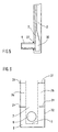
- Fig. 1 shows a cooling plate 1 and a Stavelet with a first cooling plate part 2, which faces the oven interior O i , and a second rear cooling plate part 3, which are welded together.
- the welds 4 are on the protected, cold side of the cooling plate or Stavelets.
- the cooling channel 7 Between the water-side rear side 5 of the first cooling plate part 2 as a rolled copper block and the water-side side 6 of the second cooling plate part 3 results in the cooling channel 7, which is fed with a cooling medium, preferably cooling water.
- a cooling medium preferably cooling water.
- For the water inlet and outlet pipe sections 8, 9 are mounted in bores in the second cooling plate part 3.
- the first cooling plate part 2 is designed as a solid rolling block with a flat - in the sense of non-curved - front side 14, in the transverse to the longitudinal axis of the cooling plate 1 extending grooves 15 are introduced, which facilitate the application of refractory stamping or spraying at the completion of assembly.
- the cooling channel 7 becomes rearward, i. to Oven wall pointing, with a roughly flat or slightly outward arched second cooling plate part 3 closed in the sense of an additional part. It results in a cooling channel 7 with a cross-sectional area, wherein the end portions 18, 19 - seen in relation to the longitudinal extent (x-direction) - a larger Have cross-sectional area than the central region 20th
- FIG. 2 Another preferred embodiment of a cooling plate 101 with a claimed Cooling channel cross-section, Fig. 2.
- the desired cross section of the channel 107 - here the cross section perpendicular to the longitudinal axis of the cooling plate - by the shape of the second cooling plate part 103 determined. This is twice trough-shaped.
- the troughs 121, 122 and the formation of a - here - short or longer center portion 123 is the desired cooling channel cross section with larger end areas 118, 119 compared to the center area 120 created the cross section.
- Fig. 4 shows the longitudinal section of a cooling plate 1 in mounting position on the Oven wall, for example, the wall of a blast furnace. After locking the Cooling plate 1 by means of the bridge-holder principle is the remaining space between Cooling plate 1 and furnace wall 10 filled with backfill 26.
- the Pipe sections 8 and 9 are welded to the second cooling plate part 3 (27).
- the cooling channel 7 is closed by means of caps 28, 29 at the free ends.
- FIG. 5 A further preferred embodiment of the cooling plate 1, starting from the Embodiment of FIG. 1, is shown with Fig. 5.
- the massively trained first cooling plate part 1 is in the areas that the pipe sections 8, 9 for the Water inlet or outlet opposite, further hollowed out (cavities 30) so that the entrance or exit area increases.
- This cross-sectional enlargement Slowly - ramp-like - to the course of the cooling channel wells 16, 17 adapted. This has a positive effect on a reduction from cooling water pressure losses.
- the edge areas 2a, b (or even fin areas) are not covered, there is a risk of waviness of the first Cooling plate part. This is done by inserting slots 31 in the edge areas 2a, b transversely to the longitudinal axis of the cooling plate, extending from the edge region 32 extend to approximately the second cooling plate part 3. by virtue of In the case of the slots, the edge areas can become thermally stress-free expand.
- the cooling plates according to the invention are assembled into cooling systems. They are arranged, for example, immediately next to each other, wherein their stability supported by a tongue and groove principle in the first cooling plate parts can be. Alternatively, the edge regions of the first cooling plate parts also be arranged overlapping.
- FIG. 7 A section of such a cooling system 33 comprising a plurality of cooling plates 1 and Stavelets shows the Fig. 7, with the addition of another preferred Suspension system for the stavelets on the furnace wall 10 is shown.
- each cooling plate 1 or each Stavelet several suspension points 34-39, here six each, with the respective upper suspension points 34, 35 as benchmarks and the underlying suspension points 36-39 as Losus are formed.
Landscapes
- Engineering & Computer Science (AREA)
- Chemical & Material Sciences (AREA)
- Mechanical Engineering (AREA)
- General Engineering & Computer Science (AREA)
- Metallurgy (AREA)
- Materials Engineering (AREA)
- Manufacturing & Machinery (AREA)
- Organic Chemistry (AREA)
- Blast Furnaces (AREA)
- Furnace Housings, Linings, Walls, And Ceilings (AREA)
- Heat-Exchange Devices With Radiators And Conduit Assemblies (AREA)
- Crystals, And After-Treatments Of Crystals (AREA)
- Devices That Are Associated With Refrigeration Equipment (AREA)
- Tunnel Furnaces (AREA)
Description
- Fig. 1
- einen Querschnitt einer Kühlplatte nach einer ersten Ausführungsform;
- Fig. 2
- einen Querschnitt einer Kühlplatte nach einer zweiten Ausführungsform;
- Fig. 3
- einen bevorzugt ausgebildeten zweiten Kühlplattenteil nach Fig. 2;
- Fig. 4
- einen Längsschnitt einer an einer Schachtofenwandung montierten Kühlplatte;
- Fig. 5
- einen Teilausschnitt eines Längsschnitts eines bevorzugt ausgebildeten ersten Kühlplattenteils nach Fig. 1;
- Fig. 6
- eine Seitenansicht einer Kühlplatte mit einem bevorzugt ausgebildeten ersten Kühlplattenteil;
- Fig. 7
- einen Ausschnitt eines an einer Ofenwandung montierten Kühlsystems;
- Fig. 8
- den Längsschnitt A-A einer Kühlplatte nach Fig. 7;
- Fig. 9
- den in Fig. 8 dargestellten oberen Teilausschnitt in vergrößerter Darstellung;
- Fig. 10
- die in Fig. 8 dargestellten unteren Teilausschnitte in vergrößerter Darstellung.
Claims (12)
- Kühlplatte (1, 101) für mit einer feuerfesten Auskleidung versehene Schachtöfen,
mit einem zum Ofeninneren (Oi) weisenden ersten Kühlplattenteil (2, 102) sowie einem zweiten rückwärtigen Kühlplattenteil (3, 103), die miteinander verschweißt sind, und
mit einem sich zwischen dem ersten und dem zweiten Kühlplattenteil ergebenden Kühlkanal (7, 107) sowie
mit Rohrabschnitten (8, 9) zum Kühlmitteleintritt bzw. Kühlmittelaustritt
dadurch gekennzeichnet, daß der erste Kühlplattenteil (2, 102) als Walzblock mit einer planen Frontseite (14) zum Ofeninneren (Oi) ausgebildet ist und
daß die Querschnittsfläche des Kühlkanals in Bezug auf die Längserstreckung des Querschnitts in den Endbereichen (18, 19; 118, 119) größer ist als im Mittenbereich (20; 120). - Kühlplatte nach Anspruch 1,
dadurch gekennzeichnet, daß die Endbereiche (18, 19; 118, 119) halbseitig oder beidseitig ausgewölbt sind. - Kühlplatte nach Anspruch 1 oder 2,
dadurch gekennzeichnet, daß der Kühlkanalquerschnitt auf seiner zum Ofeninneren (Oi) hinweisenden Seite durch das erste Kühlplattenteil (2) mit mindestens zwei in seiner Rückseite (5) verlaufenden Vertiefungen (16, 17) gebildet ist. - Kühlplatte nach einem der Ansprüche 1 bis 3,
dadurch gekennzeichnet, daß der Kühlkanalquerschnitt rückwärtig durch ein mindestens doppelt muldenförmig, mit zur Ofenwand hinweisenden Auswölbungen, geformtes zweites Kühlplattenteil (103) gebildet ist. - Kühlplatte nach Anspruch 3,
dadurch gekennzeichnet, daß der Kühlkanalquerschnitt rückwärtig durch ein in etwa planes zweites Kühlplattenteil (3) gebildet ist. - Kühlplatte nach Anspruch 4 oder 5,
dadurch gekennzeichnet, daß das zweite Kühlplattenteil (103) in seinem Kantenbereich (324, 325) dicker als in seinem Mittenbereich ausgebildet ist. - Kühlplatte nach einem der Ansprüche 1 bis 6,
dadurch gekennzeichnet, daß das zweite Kühlplattenteil (3, 103) mit seinen Längskanten an die Rückseite (5) des ersten Kühlplattenteils (2, 102) verschweißt ist. - Kühlplatte nach Anspruch 7,
dadurch gekennzeichnet, daß das zweite Kühlplattenteil (3) beabstandet zu den Kanten (2a, b) des ersten Kühlplattenteils (2) an dessen Rückseite verschweißt ist und in die Kantenbereiche (2a,b) des ersten Kühlplattenteils (2) senkrecht zur Längsachse der Kühlplatte mindestens ein Schlitz (31) eingebracht ist. - Kühlplatte nach einem der Ansprüche 3 bis 8,
dadurch gekennzeichnet, daß die Rohrabschnitte (8, 9) für den Kühlmitteleintritt und ― austritt durch Bohrungen im rückseitigen zweiten Kühlplattenteil (3) ragen und daß in Höhe dieser Rohrabschnitte (8, 9) der erste Kühlplattenteil (2) ausgehöhlt ist und die Tiefe der Aushöhlung (39) rampenartig zu den Kühlkanal-Vertiefungen (16,17) hin abnimmt. - Kühlplatte nach einem der Ansprüche 1 bis 9,
dadurch gekennzeichnet, daß die Kühlplatte (1, 101) zwecks Verbindung mit der Ofenwandung (10) des Schachtofens mindestens zwei Aufhängungspunkte (34, 38) aufweist, wobei ein erster Aufhängungspunkt (34) als feste Verbindung im oberen Teil der Kühlplatte und ein zweiter Aufhängungspunkt (38) als lose Verbindung im unteren Teil der Kühlplatte ausgebildet ist. - Kühlplatte nach Anspruch 10,
dadurch gekennzeichnet, daß der erste Aufhängungspunkt (34) als feste Verbindung eine Schraubenverbindung umfaßt und daß der zweite Aufhängungspunkt (38) als lose Verbindung eine Einhängeverbindung umfaßt. - System (33) zur Kühlung von mit einer feuerfesten Auskleidung versehene Schachtöfen umfassend eine Mehrzahl von nebeneinander und/oder übereinander angeordneten Kühlplatten (1, 101) aus gewalztem Kupfer oder einer gewalzten Kupferlegierung nach einem der Ansprüche 1 bis 11.
Applications Claiming Priority (3)
| Application Number | Priority Date | Filing Date | Title |
|---|---|---|---|
| DE10114720A DE10114720A1 (de) | 2001-03-23 | 2001-03-23 | Kühlplatte |
| DE10114720 | 2001-03-23 | ||
| PCT/EP2002/003186 WO2002077296A1 (de) | 2001-03-23 | 2002-03-21 | Kühlplatte |
Publications (2)
| Publication Number | Publication Date |
|---|---|
| EP1373579A1 EP1373579A1 (de) | 2004-01-02 |
| EP1373579B1 true EP1373579B1 (de) | 2005-05-25 |
Family
ID=7679025
Family Applications (1)
| Application Number | Title | Priority Date | Filing Date |
|---|---|---|---|
| EP02732511A Expired - Lifetime EP1373579B1 (de) | 2001-03-23 | 2002-03-21 | Kühlplatte |
Country Status (14)
| Country | Link |
|---|---|
| US (2) | US20040129187A1 (de) |
| EP (1) | EP1373579B1 (de) |
| JP (1) | JP2004521189A (de) |
| KR (1) | KR20030083008A (de) |
| CN (1) | CN1228454C (de) |
| AT (1) | ATE296359T1 (de) |
| BR (1) | BR0206774A (de) |
| CA (1) | CA2440169A1 (de) |
| DE (2) | DE10114720A1 (de) |
| MX (1) | MXPA03008556A (de) |
| PL (1) | PL363754A1 (de) |
| RU (1) | RU2294966C2 (de) |
| UA (1) | UA74638C2 (de) |
| WO (1) | WO2002077296A1 (de) |
Families Citing this family (9)
| Publication number | Priority date | Publication date | Assignee | Title |
|---|---|---|---|---|
| DE10114720A1 (de) * | 2001-03-23 | 2002-09-26 | Sms Demag Ag | Kühlplatte |
| EP1391521A1 (de) * | 2002-08-20 | 2004-02-25 | Voest-Alpine Industrieanlagenbau GmbH & Co. | Kühlplatte für metallurgische Öfen |
| ITGE20030033A1 (it) | 2003-05-14 | 2004-11-15 | Sms Demag S P A | Reattore siderurgico per la produzione di ghisa. |
| JP5260402B2 (ja) | 2009-04-30 | 2013-08-14 | 三菱重工業株式会社 | 板状体の製造方法、板状体、ガスタービン燃焼器およびガスタービン |
| CN103090660B (zh) * | 2011-11-04 | 2015-01-21 | 天地龙控股集团有限公司 | 竖炉不锈钢防撞段 |
| PL3562964T3 (pl) * | 2016-12-30 | 2021-05-17 | Arcelormittal | Miedziane płyty chłodzące z wielowarstwowymi występami zawierające materiał odporny za zużycie, do wielkiego pieca |
| CN108796153A (zh) * | 2018-08-30 | 2018-11-13 | 河钢股份有限公司承德分公司 | 高炉炉皮外挂冷却器及冷却方法 |
| CN109489411A (zh) * | 2018-12-29 | 2019-03-19 | 广州立中锦山合金有限公司 | 竖炉的冷却板 |
| CN114480762B (zh) * | 2022-01-21 | 2023-11-17 | 郑州宇光复合材料有限公司 | 一种高炉铸铜冷却壁 |
Family Cites Families (12)
| Publication number | Priority date | Publication date | Assignee | Title |
|---|---|---|---|---|
| LU76349A1 (de) * | 1976-12-08 | 1977-06-09 | ||
| SU658171A1 (ru) * | 1977-12-23 | 1979-04-25 | Киевский Ордена Ленина Политехнический Институт Имени 50-Летия Великой Октябрьской Социалистической Революции | Охлаждаемый элемент металлургических печей |
| SU908805A1 (ru) * | 1979-08-06 | 1982-02-28 | Предприятие П/Я А-7697 | Холодильна плита шахтной печи |
| SU1673600A1 (ru) * | 1989-05-31 | 1991-08-30 | Днепропетровский Завод Металлургического Оборудования | Холодильник доменной печи |
| US6126893A (en) * | 1996-07-09 | 2000-10-03 | Nippon Steel Corporation | Stave for cooling of blast furnace walls and method of manufacturing same |
| DE19801425C2 (de) * | 1998-01-16 | 2000-08-10 | Sms Demag Ag | Kühlplatte für Schachtöfen |
| FR2775695B1 (fr) * | 1998-03-05 | 2000-04-28 | Forcast Int | Plaque de refroidissement pour un four a cuve muni d'un revetement refractaire, et notamment pour haut fourneau |
| DE10000987A1 (de) * | 1999-04-09 | 2000-10-12 | Sms Demag Ag | Kühlplatte für Schachtöfen |
| AU776335B2 (en) * | 1999-04-09 | 2004-09-02 | Sms Demag Aktiengesellschaft | Stave for cool shaft kilns |
| DE19943287A1 (de) * | 1999-09-10 | 2001-03-15 | Sms Demag Ag | Kupferkühlplatte für metallurgische Öfen |
| DE20001397U1 (de) * | 2000-01-27 | 2000-08-10 | SMS Demag AG, 40237 Düsseldorf | Kühlplatte für Schachtöfen |
| DE10114720A1 (de) * | 2001-03-23 | 2002-09-26 | Sms Demag Ag | Kühlplatte |
-
2001
- 2001-03-23 DE DE10114720A patent/DE10114720A1/de not_active Withdrawn
-
2002
- 2002-03-21 PL PL02363754A patent/PL363754A1/xx unknown
- 2002-03-21 RU RU2003131183/02A patent/RU2294966C2/ru not_active IP Right Cessation
- 2002-03-21 DE DE50203199T patent/DE50203199D1/de not_active Expired - Fee Related
- 2002-03-21 AT AT02732511T patent/ATE296359T1/de not_active IP Right Cessation
- 2002-03-21 CN CNB028070488A patent/CN1228454C/zh not_active Expired - Fee Related
- 2002-03-21 US US10/471,063 patent/US20040129187A1/en not_active Abandoned
- 2002-03-21 WO PCT/EP2002/003186 patent/WO2002077296A1/de not_active Ceased
- 2002-03-21 BR BR0206774-9A patent/BR0206774A/pt not_active IP Right Cessation
- 2002-03-21 CA CA002440169A patent/CA2440169A1/en not_active Abandoned
- 2002-03-21 UA UA2003109520A patent/UA74638C2/uk unknown
- 2002-03-21 EP EP02732511A patent/EP1373579B1/de not_active Expired - Lifetime
- 2002-03-21 MX MXPA03008556A patent/MXPA03008556A/es not_active Application Discontinuation
- 2002-03-21 JP JP2002575336A patent/JP2004521189A/ja not_active Withdrawn
- 2002-03-21 KR KR10-2003-7012377A patent/KR20030083008A/ko not_active Ceased
-
2006
- 2006-06-28 US US11/476,473 patent/US20060279027A1/en not_active Abandoned
Also Published As
| Publication number | Publication date |
|---|---|
| DE10114720A1 (de) | 2002-09-26 |
| JP2004521189A (ja) | 2004-07-15 |
| ATE296359T1 (de) | 2005-06-15 |
| EP1373579A1 (de) | 2004-01-02 |
| RU2294966C2 (ru) | 2007-03-10 |
| CN1228454C (zh) | 2005-11-23 |
| MXPA03008556A (es) | 2004-06-30 |
| BR0206774A (pt) | 2004-02-25 |
| CN1498277A (zh) | 2004-05-19 |
| CA2440169A1 (en) | 2002-10-03 |
| US20060279027A1 (en) | 2006-12-14 |
| PL363754A1 (en) | 2004-11-29 |
| WO2002077296A1 (de) | 2002-10-03 |
| KR20030083008A (ko) | 2003-10-23 |
| US20040129187A1 (en) | 2004-07-08 |
| UA74638C2 (en) | 2006-01-16 |
| DE50203199D1 (de) | 2005-06-30 |
| RU2003131183A (ru) | 2005-02-10 |
Similar Documents
| Publication | Publication Date | Title |
|---|---|---|
| DE19719252C2 (de) | Zweiflutiger und in Luftrichtung einreihiger hartverlöteter Flachrohrverdampfer für eine Kraftfahrzeugklimaanlage | |
| EP0697090B1 (de) | Rippenrohr-wärmeaustauscher | |
| DE69503972T2 (de) | Verstärkte Endplatte für Wärmetauscher | |
| DE112005001699T5 (de) | Wärmetauscher | |
| EP1317978B1 (de) | Kokillenrohr zum Stranggiessen von Metallen | |
| DE19751356C2 (de) | Kühlelemente für Schachtöfen | |
| DE2719165C2 (de) | Kühlelement für einen metallurgischen Ofen | |
| EP1373579A1 (de) | Kühlplatte | |
| DE3419734A1 (de) | Luftgekuehlter oberflaechenkondensator | |
| DE102018115202A1 (de) | Wärmeaustauscher | |
| DE2308480A1 (de) | Waermetauscher | |
| EP1736257B1 (de) | Flüssigkeitsgekühlte Kokille zum Stranggiessen von Metallen | |
| EP1248063B1 (de) | Wärmeübertrager | |
| DE4340506A1 (de) | Heiz- oder Kühleinrichtung | |
| DE102006029043B4 (de) | Wärmeübertragungseinheit für eine Verbrennungskraftmaschine | |
| DE2703632A1 (de) | Waermetauschrohr eines radiators fuer raumtemperierung | |
| DE60014953T2 (de) | Mit Kühlplatten ausgestatteter Schachtofen und Verfahren zu seiner Herstellung | |
| DE3229757C2 (de) | Profilrohr für Wärmetauscher, insbesondere für Raumheizkörper | |
| EP3831569B1 (de) | Verfahren zur herstellung eines kunststoffprofils | |
| DE2722937A1 (de) | Rolle fuer rollenherdofen | |
| AT512324B1 (de) | Solarkollektor mit einer Vielzahl von rinnenförmigen Profilierungen | |
| DE20017369U1 (de) | Betonkerntemperierungsmodule | |
| EP1553363A1 (de) | Heiz- bzw. Kühlkörper-Verteileranordnung | |
| DE19835666C2 (de) | Temperierbares Rahmenelement | |
| DE102005007692A1 (de) | Wellenrippe für ein Kühlsystem |
Legal Events
| Date | Code | Title | Description |
|---|---|---|---|
| PUAI | Public reference made under article 153(3) epc to a published international application that has entered the european phase |
Free format text: ORIGINAL CODE: 0009012 |
|
| 17P | Request for examination filed |
Effective date: 20030708 |
|
| AK | Designated contracting states |
Kind code of ref document: A1 Designated state(s): AT BE CH CY DE DK ES FI FR GB GR IE IT LI LU MC NL PT SE TR |
|
| AX | Request for extension of the european patent |
Extension state: AL LT LV MK RO SI |
|
| GRAP | Despatch of communication of intention to grant a patent |
Free format text: ORIGINAL CODE: EPIDOSNIGR1 |
|
| GRAS | Grant fee paid |
Free format text: ORIGINAL CODE: EPIDOSNIGR3 |
|
| GRAA | (expected) grant |
Free format text: ORIGINAL CODE: 0009210 |
|
| AK | Designated contracting states |
Kind code of ref document: B1 Designated state(s): AT BE CH CY DE DK ES FI FR GB GR IE IT LI LU MC NL PT SE TR |
|
| PG25 | Lapsed in a contracting state [announced via postgrant information from national office to epo] |
Ref country code: IE Free format text: LAPSE BECAUSE OF FAILURE TO SUBMIT A TRANSLATION OF THE DESCRIPTION OR TO PAY THE FEE WITHIN THE PRESCRIBED TIME-LIMIT Effective date: 20050525 |
|
| REG | Reference to a national code |
Ref country code: GB Ref legal event code: FG4D Free format text: NOT ENGLISH |
|
| REG | Reference to a national code |
Ref country code: CH Ref legal event code: EP |
|
| REG | Reference to a national code |
Ref country code: IE Ref legal event code: FG4D Free format text: LANGUAGE OF EP DOCUMENT: GERMAN |
|
| REF | Corresponds to: |
Ref document number: 50203199 Country of ref document: DE Date of ref document: 20050630 Kind code of ref document: P |
|
| PG25 | Lapsed in a contracting state [announced via postgrant information from national office to epo] |
Ref country code: GR Free format text: LAPSE BECAUSE OF FAILURE TO SUBMIT A TRANSLATION OF THE DESCRIPTION OR TO PAY THE FEE WITHIN THE PRESCRIBED TIME-LIMIT Effective date: 20050825 Ref country code: DK Free format text: LAPSE BECAUSE OF FAILURE TO SUBMIT A TRANSLATION OF THE DESCRIPTION OR TO PAY THE FEE WITHIN THE PRESCRIBED TIME-LIMIT Effective date: 20050825 Ref country code: SE Free format text: LAPSE BECAUSE OF FAILURE TO SUBMIT A TRANSLATION OF THE DESCRIPTION OR TO PAY THE FEE WITHIN THE PRESCRIBED TIME-LIMIT Effective date: 20050825 |
|
| PG25 | Lapsed in a contracting state [announced via postgrant information from national office to epo] |
Ref country code: ES Free format text: LAPSE BECAUSE OF FAILURE TO SUBMIT A TRANSLATION OF THE DESCRIPTION OR TO PAY THE FEE WITHIN THE PRESCRIBED TIME-LIMIT Effective date: 20050905 |
|
| GBT | Gb: translation of ep patent filed (gb section 77(6)(a)/1977) |
Effective date: 20050916 |
|
| PG25 | Lapsed in a contracting state [announced via postgrant information from national office to epo] |
Ref country code: PT Free format text: LAPSE BECAUSE OF FAILURE TO SUBMIT A TRANSLATION OF THE DESCRIPTION OR TO PAY THE FEE WITHIN THE PRESCRIBED TIME-LIMIT Effective date: 20051027 |
|
| REG | Reference to a national code |
Ref country code: IE Ref legal event code: FD4D |
|
| RAP2 | Party data changed (patent owner data changed or rights of a patent transferred) |
Owner name: PAUL WURTH S.A. |
|
| PGFP | Annual fee paid to national office [announced via postgrant information from national office to epo] |
Ref country code: DE Payment date: 20060214 Year of fee payment: 5 |
|
| PGFP | Annual fee paid to national office [announced via postgrant information from national office to epo] |
Ref country code: FR Payment date: 20060215 Year of fee payment: 5 |
|
| PGFP | Annual fee paid to national office [announced via postgrant information from national office to epo] |
Ref country code: BE Payment date: 20060216 Year of fee payment: 5 |
|
| PGFP | Annual fee paid to national office [announced via postgrant information from national office to epo] |
Ref country code: AT Payment date: 20060217 Year of fee payment: 5 Ref country code: NL Payment date: 20060217 Year of fee payment: 5 |
|
| PGFP | Annual fee paid to national office [announced via postgrant information from national office to epo] |
Ref country code: GB Payment date: 20060220 Year of fee payment: 5 |
|
| NLT2 | Nl: modifications (of names), taken from the european patent patent bulletin |
Owner name: PAUL WURTH S.A. Effective date: 20060104 |
|
| PGFP | Annual fee paid to national office [announced via postgrant information from national office to epo] |
Ref country code: FI Payment date: 20060330 Year of fee payment: 5 |
|
| ET | Fr: translation filed | ||
| PG25 | Lapsed in a contracting state [announced via postgrant information from national office to epo] |
Ref country code: CH Free format text: LAPSE BECAUSE OF NON-PAYMENT OF DUE FEES Effective date: 20060331 Ref country code: MC Free format text: LAPSE BECAUSE OF NON-PAYMENT OF DUE FEES Effective date: 20060331 Ref country code: LI Free format text: LAPSE BECAUSE OF NON-PAYMENT OF DUE FEES Effective date: 20060331 |
|
| PGFP | Annual fee paid to national office [announced via postgrant information from national office to epo] |
Ref country code: IT Payment date: 20060331 Year of fee payment: 5 |
|
| PLBE | No opposition filed within time limit |
Free format text: ORIGINAL CODE: 0009261 |
|
| STAA | Information on the status of an ep patent application or granted ep patent |
Free format text: STATUS: NO OPPOSITION FILED WITHIN TIME LIMIT |
|
| PGFP | Annual fee paid to national office [announced via postgrant information from national office to epo] |
Ref country code: LU Payment date: 20060403 Year of fee payment: 5 |
|
| 26N | No opposition filed |
Effective date: 20060228 |
|
| REG | Reference to a national code |
Ref country code: CH Ref legal event code: PL |
|
| PG25 | Lapsed in a contracting state [announced via postgrant information from national office to epo] |
Ref country code: FI Free format text: LAPSE BECAUSE OF NON-PAYMENT OF DUE FEES Effective date: 20070321 |
|
| PG25 | Lapsed in a contracting state [announced via postgrant information from national office to epo] |
Ref country code: AT Free format text: LAPSE BECAUSE OF NON-PAYMENT OF DUE FEES Effective date: 20070321 |
|
| GBPC | Gb: european patent ceased through non-payment of renewal fee |
Effective date: 20070321 |
|
| NLV4 | Nl: lapsed or anulled due to non-payment of the annual fee |
Effective date: 20071001 |
|
| BERE | Be: lapsed |
Owner name: *SMS DEMAG A.G. Effective date: 20070331 |
|
| PG25 | Lapsed in a contracting state [announced via postgrant information from national office to epo] |
Ref country code: BE Free format text: LAPSE BECAUSE OF NON-PAYMENT OF DUE FEES Effective date: 20070331 |
|
| REG | Reference to a national code |
Ref country code: FR Ref legal event code: ST Effective date: 20071130 |
|
| PG25 | Lapsed in a contracting state [announced via postgrant information from national office to epo] |
Ref country code: DE Free format text: LAPSE BECAUSE OF NON-PAYMENT OF DUE FEES Effective date: 20071002 Ref country code: NL Free format text: LAPSE BECAUSE OF NON-PAYMENT OF DUE FEES Effective date: 20071001 |
|
| PG25 | Lapsed in a contracting state [announced via postgrant information from national office to epo] |
Ref country code: GB Free format text: LAPSE BECAUSE OF NON-PAYMENT OF DUE FEES Effective date: 20070321 |
|
| PG25 | Lapsed in a contracting state [announced via postgrant information from national office to epo] |
Ref country code: TR Free format text: LAPSE BECAUSE OF FAILURE TO SUBMIT A TRANSLATION OF THE DESCRIPTION OR TO PAY THE FEE WITHIN THE PRESCRIBED TIME-LIMIT Effective date: 20050525 Ref country code: FR Free format text: LAPSE BECAUSE OF NON-PAYMENT OF DUE FEES Effective date: 20070402 |
|
| PG25 | Lapsed in a contracting state [announced via postgrant information from national office to epo] |
Ref country code: CY Free format text: LAPSE BECAUSE OF FAILURE TO SUBMIT A TRANSLATION OF THE DESCRIPTION OR TO PAY THE FEE WITHIN THE PRESCRIBED TIME-LIMIT Effective date: 20050525 |
|
| PG25 | Lapsed in a contracting state [announced via postgrant information from national office to epo] |
Ref country code: LU Free format text: LAPSE BECAUSE OF NON-PAYMENT OF DUE FEES Effective date: 20070321 |
|
| PG25 | Lapsed in a contracting state [announced via postgrant information from national office to epo] |
Ref country code: IT Free format text: LAPSE BECAUSE OF NON-PAYMENT OF DUE FEES Effective date: 20070321 |