EP1372225B1 - Hochfrequenz Verbindungsvorrichtung - Google Patents
Hochfrequenz Verbindungsvorrichtung Download PDFInfo
- Publication number
- EP1372225B1 EP1372225B1 EP02405470A EP02405470A EP1372225B1 EP 1372225 B1 EP1372225 B1 EP 1372225B1 EP 02405470 A EP02405470 A EP 02405470A EP 02405470 A EP02405470 A EP 02405470A EP 1372225 B1 EP1372225 B1 EP 1372225B1
- Authority
- EP
- European Patent Office
- Prior art keywords
- bronze
- connector
- frequency
- coaxial
- weight
- Prior art date
- Legal status (The legal status is an assumption and is not a legal conclusion. Google has not performed a legal analysis and makes no representation as to the accuracy of the status listed.)
- Expired - Lifetime
Links
- 229910000906 Bronze Inorganic materials 0.000 claims description 24
- 239000010974 bronze Substances 0.000 claims description 23
- KUNSUQLRTQLHQQ-UHFFFAOYSA-N copper tin Chemical compound [Cu].[Sn] KUNSUQLRTQLHQQ-UHFFFAOYSA-N 0.000 claims description 23
- HCHKCACWOHOZIP-UHFFFAOYSA-N Zinc Chemical compound [Zn] HCHKCACWOHOZIP-UHFFFAOYSA-N 0.000 claims description 4
- 229910052725 zinc Inorganic materials 0.000 claims description 4
- 239000011701 zinc Substances 0.000 claims description 4
- 230000007613 environmental effect Effects 0.000 claims description 3
- 239000000203 mixture Substances 0.000 claims description 3
- 239000002184 metal Substances 0.000 claims description 2
- 229910052751 metal Inorganic materials 0.000 claims description 2
- 210000004907 gland Anatomy 0.000 claims 1
- 229910001369 Brass Inorganic materials 0.000 description 6
- 239000010951 brass Substances 0.000 description 6
- QGZKDVFQNNGYKY-UHFFFAOYSA-N Ammonia Chemical compound N QGZKDVFQNNGYKY-UHFFFAOYSA-N 0.000 description 4
- 230000007797 corrosion Effects 0.000 description 4
- 238000005260 corrosion Methods 0.000 description 4
- 238000005336 cracking Methods 0.000 description 4
- 239000004020 conductor Substances 0.000 description 3
- 229910000831 Steel Inorganic materials 0.000 description 2
- 229910045601 alloy Inorganic materials 0.000 description 2
- 239000000956 alloy Substances 0.000 description 2
- 229910021529 ammonia Inorganic materials 0.000 description 2
- 238000009434 installation Methods 0.000 description 2
- 239000012212 insulator Substances 0.000 description 2
- 239000010959 steel Substances 0.000 description 2
- 150000003464 sulfur compounds Chemical class 0.000 description 2
- OAICVXFJPJFONN-UHFFFAOYSA-N Phosphorus Chemical compound [P] OAICVXFJPJFONN-UHFFFAOYSA-N 0.000 description 1
- BQCADISMDOOEFD-UHFFFAOYSA-N Silver Chemical compound [Ag] BQCADISMDOOEFD-UHFFFAOYSA-N 0.000 description 1
- PDYXSJSAMVACOH-UHFFFAOYSA-N [Cu].[Zn].[Sn] Chemical compound [Cu].[Zn].[Sn] PDYXSJSAMVACOH-UHFFFAOYSA-N 0.000 description 1
- 238000005266 casting Methods 0.000 description 1
- 229920001971 elastomer Polymers 0.000 description 1
- 239000000806 elastomer Substances 0.000 description 1
- 238000003754 machining Methods 0.000 description 1
- 239000000463 material Substances 0.000 description 1
- 238000007789 sealing Methods 0.000 description 1
- 229910052709 silver Inorganic materials 0.000 description 1
- 239000004332 silver Substances 0.000 description 1
- 239000010935 stainless steel Substances 0.000 description 1
- 229910001220 stainless steel Inorganic materials 0.000 description 1
Images
Classifications
-
- H—ELECTRICITY
- H01—ELECTRIC ELEMENTS
- H01R—ELECTRICALLY-CONDUCTIVE CONNECTIONS; STRUCTURAL ASSOCIATIONS OF A PLURALITY OF MUTUALLY-INSULATED ELECTRICAL CONNECTING ELEMENTS; COUPLING DEVICES; CURRENT COLLECTORS
- H01R24/00—Two-part coupling devices, or either of their cooperating parts, characterised by their overall structure
- H01R24/38—Two-part coupling devices, or either of their cooperating parts, characterised by their overall structure having concentrically or coaxially arranged contacts
- H01R24/40—Two-part coupling devices, or either of their cooperating parts, characterised by their overall structure having concentrically or coaxially arranged contacts specially adapted for high frequency
- H01R24/56—Two-part coupling devices, or either of their cooperating parts, characterised by their overall structure having concentrically or coaxially arranged contacts specially adapted for high frequency specially adapted to a specific shape of cables, e.g. corrugated cables, twisted pair cables, cables with two screens or hollow cables
-
- H—ELECTRICITY
- H01—ELECTRIC ELEMENTS
- H01R—ELECTRICALLY-CONDUCTIVE CONNECTIONS; STRUCTURAL ASSOCIATIONS OF A PLURALITY OF MUTUALLY-INSULATED ELECTRICAL CONNECTING ELEMENTS; COUPLING DEVICES; CURRENT COLLECTORS
- H01R13/00—Details of coupling devices of the kinds covered by groups H01R12/70 or H01R24/00 - H01R33/00
- H01R13/646—Details of coupling devices of the kinds covered by groups H01R12/70 or H01R24/00 - H01R33/00 specially adapted for high-frequency, e.g. structures providing an impedance match or phase match
-
- H—ELECTRICITY
- H01—ELECTRIC ELEMENTS
- H01R—ELECTRICALLY-CONDUCTIVE CONNECTIONS; STRUCTURAL ASSOCIATIONS OF A PLURALITY OF MUTUALLY-INSULATED ELECTRICAL CONNECTING ELEMENTS; COUPLING DEVICES; CURRENT COLLECTORS
- H01R13/00—Details of coupling devices of the kinds covered by groups H01R12/70 or H01R24/00 - H01R33/00
- H01R13/02—Contact members
- H01R13/03—Contact members characterised by the material, e.g. plating, or coating materials
-
- H—ELECTRICITY
- H01—ELECTRIC ELEMENTS
- H01R—ELECTRICALLY-CONDUCTIVE CONNECTIONS; STRUCTURAL ASSOCIATIONS OF A PLURALITY OF MUTUALLY-INSULATED ELECTRICAL CONNECTING ELEMENTS; COUPLING DEVICES; CURRENT COLLECTORS
- H01R13/00—Details of coupling devices of the kinds covered by groups H01R12/70 or H01R24/00 - H01R33/00
- H01R13/46—Bases; Cases
- H01R13/52—Dustproof, splashproof, drip-proof, waterproof, or flameproof cases
-
- H—ELECTRICITY
- H01—ELECTRIC ELEMENTS
- H01R—ELECTRICALLY-CONDUCTIVE CONNECTIONS; STRUCTURAL ASSOCIATIONS OF A PLURALITY OF MUTUALLY-INSULATED ELECTRICAL CONNECTING ELEMENTS; COUPLING DEVICES; CURRENT COLLECTORS
- H01R24/00—Two-part coupling devices, or either of their cooperating parts, characterised by their overall structure
- H01R24/38—Two-part coupling devices, or either of their cooperating parts, characterised by their overall structure having concentrically or coaxially arranged contacts
- H01R24/40—Two-part coupling devices, or either of their cooperating parts, characterised by their overall structure having concentrically or coaxially arranged contacts specially adapted for high frequency
-
- H—ELECTRICITY
- H01—ELECTRIC ELEMENTS
- H01R—ELECTRICALLY-CONDUCTIVE CONNECTIONS; STRUCTURAL ASSOCIATIONS OF A PLURALITY OF MUTUALLY-INSULATED ELECTRICAL CONNECTING ELEMENTS; COUPLING DEVICES; CURRENT COLLECTORS
- H01R2103/00—Two poles
-
- H—ELECTRICITY
- H01—ELECTRIC ELEMENTS
- H01R—ELECTRICALLY-CONDUCTIVE CONNECTIONS; STRUCTURAL ASSOCIATIONS OF A PLURALITY OF MUTUALLY-INSULATED ELECTRICAL CONNECTING ELEMENTS; COUPLING DEVICES; CURRENT COLLECTORS
- H01R24/00—Two-part coupling devices, or either of their cooperating parts, characterised by their overall structure
- H01R24/38—Two-part coupling devices, or either of their cooperating parts, characterised by their overall structure having concentrically or coaxially arranged contacts
- H01R24/40—Two-part coupling devices, or either of their cooperating parts, characterised by their overall structure having concentrically or coaxially arranged contacts specially adapted for high frequency
- H01R24/42—Two-part coupling devices, or either of their cooperating parts, characterised by their overall structure having concentrically or coaxially arranged contacts specially adapted for high frequency comprising impedance matching means or electrical components, e.g. filters or switches
- H01R24/48—Two-part coupling devices, or either of their cooperating parts, characterised by their overall structure having concentrically or coaxially arranged contacts specially adapted for high frequency comprising impedance matching means or electrical components, e.g. filters or switches comprising protection devices, e.g. overvoltage protection
-
- H—ELECTRICITY
- H01—ELECTRIC ELEMENTS
- H01R—ELECTRICALLY-CONDUCTIVE CONNECTIONS; STRUCTURAL ASSOCIATIONS OF A PLURALITY OF MUTUALLY-INSULATED ELECTRICAL CONNECTING ELEMENTS; COUPLING DEVICES; CURRENT COLLECTORS
- H01R24/00—Two-part coupling devices, or either of their cooperating parts, characterised by their overall structure
- H01R24/38—Two-part coupling devices, or either of their cooperating parts, characterised by their overall structure having concentrically or coaxially arranged contacts
- H01R24/40—Two-part coupling devices, or either of their cooperating parts, characterised by their overall structure having concentrically or coaxially arranged contacts specially adapted for high frequency
- H01R24/56—Two-part coupling devices, or either of their cooperating parts, characterised by their overall structure having concentrically or coaxially arranged contacts specially adapted for high frequency specially adapted to a specific shape of cables, e.g. corrugated cables, twisted pair cables, cables with two screens or hollow cables
- H01R24/564—Corrugated cables
Definitions
- the invention relates to a device according to the preamble of claim 1.
- stainless steel is used in high-frequency engineering according to the international standard "Fed. Spec. QQ-S-764".
- this steel causes passive intermodulation products and therefore can not be used in a variety of high frequency applications.
- brass according to the standard "QQ-B-626” is also used.
- brass has the disadvantage of stress corrosion cracking and must therefore be protected against aggressive environmental influences in an outdoor use and in particular in a humid, dirty environment installation, additionally with insulating tape or shrink tubing. This will incur additional costs during installation.
- the US-A-3,568,111 discloses a device of the type mentioned, in which a cylindrical housing is made of bronze.
- the invention has for its object to provide a device of the type mentioned, which is largely resistant to stress corrosion cracking in aggressive ambient atmosphere, but still comparable in terms of electrical properties, machinability and galvanizability with brass is and generates negligible passive intermodulation products.
- the object is achieved in a high-frequency component of the type mentioned according to claim 1.
- bronze and in particular cast bronze, is much more stable than aggressive media, especially ammonia and sulfur compounds.
- Bronze is much less susceptible to stress corrosion cracking, especially in the case of mechanical stresses, even with residual stresses in the aforementioned aggressive media.
- the resistance in aggressive media is guaranteed even if the components are not protected by heat shrink tubing, tape and the like and thus exposed to the ambient atmosphere directly.
- the use of bronze as a contact part in electrical components is known per se.
- a significant advantage of the high-frequency component according to the invention is seen in the fact that bronze can be processed essentially as inexpensively as brass.
- bronze alloys can be machined by machining and in this way connectors can be produced in a cost-effective manner.
- the replacement of brass by bronze, in particular cast bronze is thus possible at essentially no additional cost.
- the high-frequency component is in particular and preferably a coaxial connector or a lightning protection component.
- a particularly high resistance results from the fact that the proportion of zinc less than 7% by weight, preferably about 6% by weight.
- a particularly preferred alloy has the composition CuZn6Sn4Pb3.
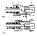
- FIGS. 1 and 2 show a section through a coaxial connector according to the invention.
- the high-frequency component is a coaxial plug 2, which has a housing 3 to which a coaxial cable 10 with a nut 4 is releasably attached.
- the coaxial cable 10 has in known manner an inner conductor 11, an insulator 12, a corrugated sheath 13 as an outer conductor and a sheath 14.
- the inner conductor 11 is connected via a connecting sleeve 19 with a plug pin 20 which is surrounded by an insulator 21.
- With a further nut 28 of the coaxial connector 2 is screwed to a plug part, not shown here.
- the nut 4 is not completely screwed onto the housing 3.
- a sealing mass 7, for example, an elastomer partially displaced in an annular space 9 and seals this case a screwed onto the corrugated sheath 13 threaded ring 17 to the outside.
- the front end of the corrugated sheath 13 is deformed when screwing the nut 4 as shown.
- a ring 8 limits the depth of engagement of the nut. 4
- the two nuts 4 and 28 and the housing 3 are made of bronze, in particular cast bronze.
- the outwardly protected threaded ring 17 may be made as usual from brass.
- the two nuts 4 and 28 are preferably on their surfaces refined, for example, silvered, whereby the contact resistance is improved.
- the pin 20 is preferably made of bronze, in particular cast bronze and finished on its surface, in particular silver plated.
- the bronze preferably has a comparatively low zinc content.
- the bronze has a zinc content of less than 7% by weight.
- the copper-tin-zinc casting alloy used is preferably a lead-containing multi-metal bronze and has, for example, the composition CuZn6Sn4Pb3.
- the device according to the invention is, for example, part of a high-frequency lightning protection component, a component of an external antenna, a power divider or a high-frequency coupler.
- the bronze used thus forms supporting, exposed to the ambient atmosphere and under mechanical tension parts of the coaxial connector 1. It is also at mechanical stresses in corrosive media, such as ammonia and sulfur compounds, resistant. The resistance relates in particular to stress corrosion cracking, which can lead to breakage of the components.
- the connecting part 1 is therefore particularly suitable for outdoor applications, for example for outdoor antenna systems, which are permanently exposed to the environmental atmosphere. Additional protection is therefore not required even with aggressive media. The surfaces can thus be exposed directly to the ambient atmosphere.
Landscapes
- Coupling Device And Connection With Printed Circuit (AREA)
- Connector Housings Or Holding Contact Members (AREA)
- Details Of Aerials (AREA)
Description
- Die Erfindung betrifft eine Vorrichtung nach dem Oberbegriff des Anspruchs 1.
- Für Vorrichtungen zum elektrischen Kontaktieren von beispielsweise Koaxialkabeln wird in der Hochfrequenztechnik nach der internationalen Norm "Fed. Spec. QQ-S-764" rostfreier Stahl (Stainless Steel) verwendet. Dieser Stahl verursacht jedoch passive Intermodulationsprodukte und kann daher in einer Vielzahl von Hochfrequenzanwendungen nicht verwendet werden. Alternativ zum genannten Stahl werden deshalb auch Messing nach der Norm "QQ-B-626" verwendet. Messing weist jedoch den Nachteil der Spannungsrisskorrosion auf und muss daher bei einem Ausseneinsatz und insbesondere bei einer Installation in feuchter, verschmutzter Umgebung zusätzlich mit isolierendem Band oder einem Schrumpfschlauch gegen aggressive Umwelteinflüsse geschützt werden. Dadurch werden zusätzliche Kosten bei der Installation verursacht.
- Die
US-A-3,568,111 offenbart eine Vorrichtung der genannten Art, bei welcher ein zylindrisches Gehäuse aus Bronze hergestellt ist. - Der Erfindung liegt die Aufgabe zugrunde, eine Vorrichtung der genannten Art zu schaffen, die in aggressiver Umgebungsatmosphäre gegen Spannungsrisskorrosion weitgehend resistent ist, aber dennoch bezüglich den elektrischen Eigenschaften, maschineller Bearbeitbarkeit sowie Galvanisierbarkeit mit Messing vergleichbar ist und vernachlässigbare passive Intermodulationsprodukte erzeugt.
Die Aufgabe ist bei einer Hochfrequenzkomponente der genannten Art gemäss Anspruch 1 gelöst. Untersuchungen haben gezeigt, dass Bronze und insbesondere Gussbronze gegenüber aggressiven Medien und insbesondere Ammoniak sowie Schwefelverbindungen wesentlich stabiler ist als Messing. Bronze ist insbesondere bei mechanischen Spannungen, auch bei Eigenspannungen in den genannten aggressiven Medien wesentlich weniger anfällig gegen Spannungsrisskorrosion. Die Beständigkeit in aggressiven Medien ist auch dann gewährleistet, wenn die Komponenten nicht durch Schrumpfschläuche, Klebeband und desgleichen geschützt und somit der Umgebungsatmosphäre direkt ausgesetzt sind. Die Verwendung von Bronze als Kontaktteil bei elektrischen Komponenten ist an sich bekannt. Beispielsweise zeigen dieEP 1 209 771A ,US 2002/0034 890 und dieEP 0 858 133A Federbuchsen und eine Kontaktklammer aus Phosphorbronze. Die Bronze wird hier als Federwerkstoff verwendet. Die oben genannte Aufgabe wird aber dadurch nicht gelöst. Angestrebt wird hier lediglich ein besserer Kontakt. - Ein wesentlicher Vorteil der erfindungsgemässen Hochfrequenzkomponente wird darin gesehen, dass Bronze im Wesentlichen ebenso kostengünstig bearbeitet werden kann wie Messing. Insbesondere lassen sich Bronzelegierungen durch Zerspanen bearbeiten und auf diese Weise können insbesondere kostengünstig Verbinder hergestellt werden. Der Ersatz von Messing durch Bronze, insbesondere Gussbronze ist somit im Wesentlichen ohne zusätzliche Kosten möglich.
- Die Hochfrequenzkomponente ist insbesondere und vorzugsweise ein Koaxialverbinder oder eine Blitzschutzkomponente.
- Eine besonders hohe Beständigkeit ergibt sich dadurch, dass der Anteil von Zink kleiner als 7Gew.% vorzugsweise etwa 6Gew.% ist. Eine besonders bevorzugte Legierung besitzt die Zusammensetzung CuZn6Sn4Pb3.
- Ein Ausführungsbeispiel einer erfindungsgemässen Hochfrequenzkomponente wird nachfolgend anhand der Figuren 1 und 2 erläutert, die jeweils einen Schnitt durch einen erfindungsgemässen Koaxialstecker zeigen.
- Die Hochfrequenzkomponente ist gemäss den Figuren 1 und 2 ein Koaxialstecker 2, der ein Gehäuse 3 autweist, an dem ein Koaxialkabel 10 mit einer Mutter 4 lösbar befestigt ist. Das Koaxialkabel 10 weist in an sich bekannter Weise einen Innenleiter 11, einen Isolator 12, einen Wellmantel 13 als Aussenleiter und eine Hülle 14 auf. Der Innenleiter 11 ist über eine Verbindungshülse 19 mit einem Steckerstift 20 verbunden, der von einem Isolator 21 umgeben ist. Mit einer weiteren Mutter 28 wird der Koaxialstecker 2 mit einem hier nicht gezeigten Steckerteil verschraubt.
- In der Figur 1 ist die Mutter 4 noch nicht vollständig auf das Gehäuse 3 aufgeschraubt. Beim weiteren Aufschrauben der Mutter 4 bis zu der in Figur 2 gezeigten Position wird eine dichtende Masse 7, aus beispielsweise einem Elastomer teilweise in einen Ringraum 9 verdrängt und dichtet hierbei einen auf den Wellmantel 13 aufgeschraubten Gewindering 17 nach aussen ab. Das vordere Ende des Wellmantels 13 wird beim Aufschrauben der Mutter 4 wie ersichtlich deformiert. Ein Ring 8 begrenzt die Einschraubtiefe der Mutter 4.
- Die beiden Muttern 4 und 28 als auch das Gehäuse 3 sind aus Bronze, insbesondere Gussbronze hergestellt. Der nach aussen geschützte Gewindering 17 kann wie üblich aus Messing hergestellt sein. Die beiden Muttern 4 und 28 sind an ihren Oberflächen vorzugsweise veredelt, beispielsweise versilbert, wodurch der Kontaktwiderstand verbessert wird. Ebenfalls ist der Steckerstift 20 vorzugsweise aus Bronze, insbesondere Gussbronze hergestellt und an seiner Oberfläche veredelt, insbesondere versilbert.
- Die Bronze weist vorzugsweise einen vergleichsweise tiefen Zinkanteil auf. Die Bronze besitzt einen Zinkanteil von weniger als 7Gew.%.
- Die verwendete Kupfer-Zinn-Zink-Gusslegierung ist vorzugsweise eine Mehrstoffbronze mit Blei und besitzt beispielsweise die Zusammensetzung CuZn6Sn4Pb3.
- Die erfindungsgemässe Vorrichtung ist beispielsweise Teil einer Hochfrequenz-Blitzschutzkomponente, eine Komponente einer Aussenantenne, eines Leistungteilers oder eines Hochfrequenzkopplers.
- Die verwendete Bronze bildet somit tragende, der Umgebungsatmosphäre ausgesetzte sowie unter mechanischer Spannung stehende Teile des Koaxialsteckers 1. Sie ist auch bei mechanischen Spannungen in korrosiven Medien, beispielsweise Ammoniak und Schwefelverbindungen, beständig. Die Beständigkeit betrifft insbesondere diejenige gegen Spannungsrisskorrosion, die zu einem Brechen der Komponenten führen kann. Der Verbindungsteil 1 eignet sich deshalb besonderes für Aussenanwendungen, beispielsweise für Aussenantennenanlagen, welche der Umweltatmosphäre dauernd ausgesetzt sind. Ein zusätzlicher Schutz ist somit auch bei aggressiven Medien nicht erforderlich. Die Oberflächen können somit direkt der Umgebungsatmosphäre ausgesetzt sein.
Claims (8)
- Vorrichtung zum elektrischen Kontaktieren eines elektrisch leitenden Teils einer Hochfrequenzanlage, beispielsweise eines Koaxial-Kabels oder Wellrohr-Koaxialkabels oder Koaxialsteckverbinders, mit wenigstens einem tragenden Körper (3, 4, 28) aus Metall, der einen Innenleiter (11, 19, 20) umgibt, wobei wenigstens der tragende und den Umwelteinflüssen ausgesetzte Körper (3, 4, 28) aus Bronze hergestellt ist, dadurch gekennzeichnet, dass eine Bronze verwendet wird, bei welcher der Anteil an Zink kleiner als 7 Gew.%, vorzugsweise etwa 6 Gew.% ist.
- Vorrichtung nach Anspruch 1, dadurch gekennzeichnet, dass sie ein elektrischer Verbinder oder Verbinderteil (1) ist.
- Vorrichtung nach Anspruch 2, dadurch gekennzeichnet, dass der Verbinderteil (1) ein Teil eines Koaxialverbinders ist.
- Vorrichtung nach Anspruch 1, dadurch gekennzeichnet, dass sie ein Teil einer Hochfrequenz-Blitzschutzkomponente ist.
- Vorrichtung nach einem der Ansprüche 1 bis 4, dadurch gekennzeichnet, dass sie eine elektrische Komponente für eine Aussenantenne ist.
- Vorrichtung nach Anspruch 1, dadurch gekennzeichnet, dass sie ein Teil einer Kabelverschraubung, eines Leistungsteilers, eines Hochfrequenzfilters oder eines Hochfrequenzkopplers ist.
- Vorrichtung nach einem der Ansprüche 1 bis 6, dadurch gekennzeichnet, dass die Bronze eine Mehrstoffbronze mit Blei ist.
- Vorrichtung nach einem der Ansprüche 1 bis 8, dadurch gekennzeichnet, dass die Bronze die Zusammensetzung CuZn6Sn4Pb3 aufweist.
Priority Applications (8)
| Application Number | Priority Date | Filing Date | Title |
|---|---|---|---|
| EP02405470A EP1372225B1 (de) | 2002-06-10 | 2002-06-10 | Hochfrequenz Verbindungsvorrichtung |
| DE50210349T DE50210349D1 (de) | 2002-06-10 | 2002-06-10 | Hochfrequenz Verbindungsvorrichtung |
| KR10-2004-7019959A KR20050010869A (ko) | 2002-06-10 | 2003-05-12 | 고주파 시스템의 전기 전도성 부분과 전기적 접속을 위한 장치 |
| AU2003222705A AU2003222705B2 (en) | 2002-06-10 | 2003-05-12 | Device for electronically contacting an electrically conductive part of a high-frequency system |
| US10/517,579 US20050239327A1 (en) | 2002-06-10 | 2003-05-12 | Device for electronically contacting an electrically conductive part of a high-frequency system |
| CNB038135744A CN100356635C (zh) | 2002-06-10 | 2003-05-12 | 与高频系统的导电部件进行电接触的装置 |
| JP2004512239A JP2005529471A (ja) | 2002-06-10 | 2003-05-12 | 高周波設備の導電部の電気的接触を行うための装置 |
| PCT/CH2003/000301 WO2003105283A1 (de) | 2002-06-10 | 2003-05-12 | Vorrichtung zum elektronischen kontaktieren eines elektrisch leitenden teils einer hochfrequenzanlage |
Applications Claiming Priority (1)
| Application Number | Priority Date | Filing Date | Title |
|---|---|---|---|
| EP02405470A EP1372225B1 (de) | 2002-06-10 | 2002-06-10 | Hochfrequenz Verbindungsvorrichtung |
Publications (2)
| Publication Number | Publication Date |
|---|---|
| EP1372225A1 EP1372225A1 (de) | 2003-12-17 |
| EP1372225B1 true EP1372225B1 (de) | 2007-06-20 |
Family
ID=29558468
Family Applications (1)
| Application Number | Title | Priority Date | Filing Date |
|---|---|---|---|
| EP02405470A Expired - Lifetime EP1372225B1 (de) | 2002-06-10 | 2002-06-10 | Hochfrequenz Verbindungsvorrichtung |
Country Status (8)
| Country | Link |
|---|---|
| US (1) | US20050239327A1 (de) |
| EP (1) | EP1372225B1 (de) |
| JP (1) | JP2005529471A (de) |
| KR (1) | KR20050010869A (de) |
| CN (1) | CN100356635C (de) |
| AU (1) | AU2003222705B2 (de) |
| DE (1) | DE50210349D1 (de) |
| WO (1) | WO2003105283A1 (de) |
Families Citing this family (16)
| Publication number | Priority date | Publication date | Assignee | Title |
|---|---|---|---|---|
| US7344381B2 (en) * | 2004-04-29 | 2008-03-18 | Emerson Network Power Connectivity Solutions, Inc. | High frequency edge mount connector |
| CA2563865C (en) * | 2005-10-20 | 2010-04-27 | Thomas & Betts International, Inc. | Prepless coaxial cable connector |
| KR100593500B1 (ko) * | 2005-11-23 | 2006-06-30 | (주)기가레인 | 고주파 코넥터용 플러그 |
| CN101064402B (zh) * | 2006-04-29 | 2010-09-08 | 中国电子科技集团公司第二十三研究所 | 一种低互调的射频同轴连接器 |
| US7156696B1 (en) * | 2006-07-19 | 2007-01-02 | John Mezzalingua Associates, Inc. | Connector for corrugated coaxial cable and method |
| US7357672B2 (en) * | 2006-07-19 | 2008-04-15 | John Mezzalingua Associates, Inc. | Connector for coaxial cable and method |
| EP2063500A1 (de) * | 2007-11-22 | 2009-05-27 | Alcatel Lucent | Koaxiale Kabelverbindung und koaxiale Kabelanordnung |
| KR101671810B1 (ko) * | 2010-03-02 | 2016-11-02 | 엘에스전선 주식회사 | 동축케이블용 커넥터 |
| CN104966969B (zh) * | 2015-07-15 | 2017-04-19 | 鞍山中关科技有限公司 | 用于电磁脉冲能量传输的电缆快速换线机构 |
| US10637186B2 (en) * | 2016-06-29 | 2020-04-28 | John Mezzalingua Associates, LLC | Hybrid feed-through connector for coaxial cables |
| USD830306S1 (en) * | 2017-03-27 | 2018-10-09 | Huber+Suhner Ag | Electrical connector |
| CN108336617B (zh) * | 2018-04-04 | 2023-12-15 | 营口致远科技有限公司 | 安装快捷的射频同轴连接器 |
| CN108649309A (zh) * | 2018-05-18 | 2018-10-12 | 斯必能通讯器材(上海)有限公司 | 一种用于滤波器产品中的可调式输入耦合结构 |
| CN110970766A (zh) * | 2019-12-09 | 2020-04-07 | 江西博硕电子有限公司 | 一种压接式射频同轴连接器 |
| KR102432690B1 (ko) * | 2021-07-26 | 2022-08-17 | 주식회사유비씨에스 | 통신 케이블용 커넥터 어셈블리 |
| KR102432691B1 (ko) * | 2021-07-26 | 2022-08-17 | 주식회사유비씨에스 | 통신 케이블용 커넥터 어셈블리 |
Citations (1)
| Publication number | Priority date | Publication date | Assignee | Title |
|---|---|---|---|---|
| US3568111A (en) * | 1968-10-01 | 1971-03-02 | Raytheon Co | Connector for flexible transmission line |
Family Cites Families (15)
| Publication number | Priority date | Publication date | Assignee | Title |
|---|---|---|---|---|
| US2309100A (en) * | 1941-08-16 | 1943-01-26 | Chase Brass & Copper Co | Copper base alloy |
| US6620460B2 (en) * | 1992-04-15 | 2003-09-16 | Jet-Lube, Inc. | Methods for using environmentally friendly anti-seize/lubricating systems |
| US5987749A (en) * | 1992-09-21 | 1999-11-23 | U.S. Philips Corporation | Method of manufacturing a dynamic groove bearing, die suitable for use in such a method, and housing and bearing part manufactured by such a method |
| GB9619552D0 (en) * | 1996-09-19 | 1996-10-30 | Itt Ind Ltd | Coaxial connector body |
| CN2372801Y (zh) * | 1999-06-11 | 2000-04-05 | 北京三维电器公司 | 射频同轴电缆连接器 |
| DE10055992C2 (de) * | 2000-04-07 | 2003-07-10 | Spinner Gmbh Elektrotech | Verlötbarer koaxialer Steckverbinder |
| EP1295362B1 (de) * | 2000-06-30 | 2010-10-13 | Daume Patentbesitzgesellschaft mbH & Co. KG | Elektrisch leitende rohr- oder kabelschelle |
| JP3446726B2 (ja) * | 2000-08-11 | 2003-09-16 | 株式会社村田製作所 | 可動端子、同軸コネクタ及び通信装置 |
| US6830629B2 (en) * | 2000-08-31 | 2004-12-14 | The Ford Meter Box Company, Inc. | Method for treating brass |
| US6447616B1 (en) * | 2000-08-31 | 2002-09-10 | The Ford Meter Box Company | Method for treating brass |
| US6558177B2 (en) * | 2000-11-22 | 2003-05-06 | Tyco Electronics Corporation | Floating coaxial connector |
| US6759087B1 (en) * | 2002-04-10 | 2004-07-06 | Conspectus, Inc. | Solution for sealing porous metal substrates and process of applying the solution |
| US6789680B2 (en) * | 2002-06-13 | 2004-09-14 | Varco I/P, Inc. | Screen assembly for vibratory separator |
| US6905367B2 (en) * | 2002-07-16 | 2005-06-14 | Silicon Bandwidth, Inc. | Modular coaxial electrical interconnect system having a modular frame and electrically shielded signal paths and a method of making the same |
| US6712050B1 (en) * | 2002-11-04 | 2004-03-30 | Luis Gomez | Apparatus for improving combustion efficiency in internal combustion systems |
-
2002
- 2002-06-10 DE DE50210349T patent/DE50210349D1/de not_active Expired - Fee Related
- 2002-06-10 EP EP02405470A patent/EP1372225B1/de not_active Expired - Lifetime
-
2003
- 2003-05-12 US US10/517,579 patent/US20050239327A1/en not_active Abandoned
- 2003-05-12 JP JP2004512239A patent/JP2005529471A/ja active Pending
- 2003-05-12 KR KR10-2004-7019959A patent/KR20050010869A/ko not_active Ceased
- 2003-05-12 AU AU2003222705A patent/AU2003222705B2/en not_active Ceased
- 2003-05-12 WO PCT/CH2003/000301 patent/WO2003105283A1/de not_active Ceased
- 2003-05-12 CN CNB038135744A patent/CN100356635C/zh not_active Expired - Fee Related
Patent Citations (1)
| Publication number | Priority date | Publication date | Assignee | Title |
|---|---|---|---|---|
| US3568111A (en) * | 1968-10-01 | 1971-03-02 | Raytheon Co | Connector for flexible transmission line |
Also Published As
| Publication number | Publication date |
|---|---|
| AU2003222705B2 (en) | 2007-06-14 |
| JP2005529471A (ja) | 2005-09-29 |
| AU2003222705A1 (en) | 2003-12-22 |
| WO2003105283A1 (de) | 2003-12-18 |
| US20050239327A1 (en) | 2005-10-27 |
| CN100356635C (zh) | 2007-12-19 |
| EP1372225A1 (de) | 2003-12-17 |
| KR20050010869A (ko) | 2005-01-28 |
| DE50210349D1 (de) | 2007-08-02 |
| CN1659746A (zh) | 2005-08-24 |
Similar Documents
| Publication | Publication Date | Title |
|---|---|---|
| WO2003105283A1 (de) | Vorrichtung zum elektronischen kontaktieren eines elektrisch leitenden teils einer hochfrequenzanlage | |
| EP0553766B1 (de) | Kabelsteckverbinder und Kabeldurchführung | |
| WO2018154074A1 (de) | Steckverbinder, insbesondere für eine hochstromanwendung | |
| EP3163690A1 (de) | Stecker mit federkorb auf anschlussseite | |
| EP1470620B1 (de) | Polklemme | |
| EP3387710A1 (de) | Aussenleiteranordnung für einen koaxial-steckverbinder | |
| DE10258689B3 (de) | Koaxiale Steckverbindung | |
| EP3574559A1 (de) | Kabeldurchführung mit abschirmenden und abdichtenden eigenschaften | |
| WO2016169990A1 (de) | Steckverbindersystem | |
| EP1467441A2 (de) | Schnellanschliessbare Steckverbindung in Spannzangentechnik | |
| DE102010052627A1 (de) | Mantelleitungscrimpverbindung für Zug- und Druckentlastung einschließlich Schirmübertragung zur Metallhülse | |
| DE202011002286U1 (de) | Kabelverschraubunng mit Kontaktfeder | |
| EP3832806A1 (de) | Federhülse, schirmhülse zur kontaktierung von schirmungselementen | |
| EP0415136B1 (de) | Steckereinsatz für ein Metallrohrgehäuse | |
| DE2932612C3 (de) | Kabelschirmerdung | |
| CH684910A5 (de) | Koaxialer Steckverbinder. | |
| DE202012101303U1 (de) | Steckverbindergehäuse | |
| DE102011106736A1 (de) | Gehäusestecker und Gehäusebuchse sowie Werkzeug dafür | |
| EP3680991B1 (de) | Elektrisch geschirmte kupplungsanordnung und verwendung einer solchen | |
| DE202012001446U1 (de) | Elektrischer Kontaktpin für Ultraschallschweißen | |
| EP4566130B1 (de) | Strombuchse zur lösbaren verbindung mit einem stromstecker sowie stromkupplung bestehend aus einer solchen strombuchse sowie einem zugehörigen stromstecker | |
| DE102006003236A1 (de) | Kuppler, insbesondere Winkelkuppler nach dem Fakra-Standard, für fahrzeugtechnische Anwendungen | |
| EP4254683B1 (de) | Rundsteckverbinder und verfahren zum herstellen eines rundsteckverbinders | |
| EP4238188B1 (de) | Steckverbinderanordnung | |
| DE2557031B2 (de) | Opferanode, insbesondere zur verwendung bei einem metalltank |
Legal Events
| Date | Code | Title | Description |
|---|---|---|---|
| PUAI | Public reference made under article 153(3) epc to a published international application that has entered the european phase |
Free format text: ORIGINAL CODE: 0009012 |
|
| AK | Designated contracting states |
Kind code of ref document: A1 Designated state(s): AT BE CH CY DE DK ES FI FR GB GR IE IT LI LU MC NL PT SE TR |
|
| AX | Request for extension of the european patent |
Extension state: AL LT LV MK RO SI |
|
| 17P | Request for examination filed |
Effective date: 20040204 |
|
| AKX | Designation fees paid |
Designated state(s): CH DE FR LI SE |
|
| 17Q | First examination report despatched |
Effective date: 20060919 |
|
| GRAP | Despatch of communication of intention to grant a patent |
Free format text: ORIGINAL CODE: EPIDOSNIGR1 |
|
| GRAS | Grant fee paid |
Free format text: ORIGINAL CODE: EPIDOSNIGR3 |
|
| GRAA | (expected) grant |
Free format text: ORIGINAL CODE: 0009210 |
|
| AK | Designated contracting states |
Kind code of ref document: B1 Designated state(s): CH DE FR LI SE |
|
| REG | Reference to a national code |
Ref country code: CH Ref legal event code: EP |
|
| REF | Corresponds to: |
Ref document number: 50210349 Country of ref document: DE Date of ref document: 20070802 Kind code of ref document: P |
|
| REG | Reference to a national code |
Ref country code: CH Ref legal event code: NV Representative=s name: ISLER & PEDRAZZINI AG |
|
| REG | Reference to a national code |
Ref country code: CH Ref legal event code: PCAR Free format text: ISLER & PEDRAZZINI AG;POSTFACH 1772;8027 ZUERICH (CH) |
|
| REG | Reference to a national code |
Ref country code: SE Ref legal event code: TRGR |
|
| ET | Fr: translation filed | ||
| PLBE | No opposition filed within time limit |
Free format text: ORIGINAL CODE: 0009261 |
|
| STAA | Information on the status of an ep patent application or granted ep patent |
Free format text: STATUS: NO OPPOSITION FILED WITHIN TIME LIMIT |
|
| 26N | No opposition filed |
Effective date: 20080325 |
|
| PGFP | Annual fee paid to national office [announced via postgrant information from national office to epo] |
Ref country code: CH Payment date: 20080417 Year of fee payment: 7 |
|
| PGFP | Annual fee paid to national office [announced via postgrant information from national office to epo] |
Ref country code: SE Payment date: 20080519 Year of fee payment: 7 Ref country code: DE Payment date: 20080523 Year of fee payment: 7 |
|
| REG | Reference to a national code |
Ref country code: CH Ref legal event code: PL |
|
| REG | Reference to a national code |
Ref country code: FR Ref legal event code: ST Effective date: 20100226 |
|
| PG25 | Lapsed in a contracting state [announced via postgrant information from national office to epo] |
Ref country code: LI Free format text: LAPSE BECAUSE OF NON-PAYMENT OF DUE FEES Effective date: 20090630 Ref country code: FR Free format text: LAPSE BECAUSE OF NON-PAYMENT OF DUE FEES Effective date: 20090630 Ref country code: CH Free format text: LAPSE BECAUSE OF NON-PAYMENT OF DUE FEES Effective date: 20090630 |
|
| PGFP | Annual fee paid to national office [announced via postgrant information from national office to epo] |
Ref country code: FR Payment date: 20080513 Year of fee payment: 7 |
|
| PG25 | Lapsed in a contracting state [announced via postgrant information from national office to epo] |
Ref country code: DE Free format text: LAPSE BECAUSE OF NON-PAYMENT OF DUE FEES Effective date: 20100101 |
|
| PG25 | Lapsed in a contracting state [announced via postgrant information from national office to epo] |
Ref country code: SE Free format text: LAPSE BECAUSE OF NON-PAYMENT OF DUE FEES Effective date: 20090611 |