EP1369921A2 - Semiconductor package and method for packaging a semiconductor - Google Patents
Semiconductor package and method for packaging a semiconductor Download PDFInfo
- Publication number
- EP1369921A2 EP1369921A2 EP03012778A EP03012778A EP1369921A2 EP 1369921 A2 EP1369921 A2 EP 1369921A2 EP 03012778 A EP03012778 A EP 03012778A EP 03012778 A EP03012778 A EP 03012778A EP 1369921 A2 EP1369921 A2 EP 1369921A2
- Authority
- EP
- European Patent Office
- Prior art keywords
- substrate
- electrode pad
- semiconductor package
- package
- hole
- Prior art date
- Legal status (The legal status is an assumption and is not a legal conclusion. Google has not performed a legal analysis and makes no representation as to the accuracy of the status listed.)
- Withdrawn
Links
Images


Classifications
-
- H—ELECTRICITY
- H01—ELECTRIC ELEMENTS
- H01L—SEMICONDUCTOR DEVICES NOT COVERED BY CLASS H10
- H01L23/00—Details of semiconductor or other solid state devices
- H01L23/48—Arrangements for conducting electric current to or from the solid state body in operation, e.g. leads, terminal arrangements ; Selection of materials therefor
-
- H—ELECTRICITY
- H05—ELECTRIC TECHNIQUES NOT OTHERWISE PROVIDED FOR
- H05K—PRINTED CIRCUITS; CASINGS OR CONSTRUCTIONAL DETAILS OF ELECTRIC APPARATUS; MANUFACTURE OF ASSEMBLAGES OF ELECTRICAL COMPONENTS
- H05K3/00—Apparatus or processes for manufacturing printed circuits
- H05K3/30—Assembling printed circuits with electric components, e.g. with resistor
- H05K3/32—Assembling printed circuits with electric components, e.g. with resistor electrically connecting electric components or wires to printed circuits
- H05K3/34—Assembling printed circuits with electric components, e.g. with resistor electrically connecting electric components or wires to printed circuits by soldering
- H05K3/3452—Solder masks
-
- H—ELECTRICITY
- H01—ELECTRIC ELEMENTS
- H01L—SEMICONDUCTOR DEVICES NOT COVERED BY CLASS H10
- H01L23/00—Details of semiconductor or other solid state devices
- H01L23/12—Mountings, e.g. non-detachable insulating substrates
- H01L23/14—Mountings, e.g. non-detachable insulating substrates characterised by the material or its electrical properties
- H01L23/15—Ceramic or glass substrates
-
- H—ELECTRICITY
- H01—ELECTRIC ELEMENTS
- H01L—SEMICONDUCTOR DEVICES NOT COVERED BY CLASS H10
- H01L23/00—Details of semiconductor or other solid state devices
- H01L23/48—Arrangements for conducting electric current to or from the solid state body in operation, e.g. leads, terminal arrangements ; Selection of materials therefor
- H01L23/488—Arrangements for conducting electric current to or from the solid state body in operation, e.g. leads, terminal arrangements ; Selection of materials therefor consisting of soldered or bonded constructions
- H01L23/498—Leads, i.e. metallisations or lead-frames on insulating substrates, e.g. chip carriers
- H01L23/49811—Additional leads joined to the metallisation on the insulating substrate, e.g. pins, bumps, wires, flat leads
- H01L23/49816—Spherical bumps on the substrate for external connection, e.g. ball grid arrays [BGA]
-
- H—ELECTRICITY
- H01—ELECTRIC ELEMENTS
- H01L—SEMICONDUCTOR DEVICES NOT COVERED BY CLASS H10
- H01L23/00—Details of semiconductor or other solid state devices
- H01L23/48—Arrangements for conducting electric current to or from the solid state body in operation, e.g. leads, terminal arrangements ; Selection of materials therefor
- H01L23/488—Arrangements for conducting electric current to or from the solid state body in operation, e.g. leads, terminal arrangements ; Selection of materials therefor consisting of soldered or bonded constructions
- H01L23/498—Leads, i.e. metallisations or lead-frames on insulating substrates, e.g. chip carriers
- H01L23/49827—Via connections through the substrates, e.g. pins going through the substrate, coaxial cables
-
- H—ELECTRICITY
- H01—ELECTRIC ELEMENTS
- H01L—SEMICONDUCTOR DEVICES NOT COVERED BY CLASS H10
- H01L2924/00—Indexing scheme for arrangements or methods for connecting or disconnecting semiconductor or solid-state bodies as covered by H01L24/00
- H01L2924/0001—Technical content checked by a classifier
- H01L2924/0002—Not covered by any one of groups H01L24/00, H01L24/00 and H01L2224/00
-
- H—ELECTRICITY
- H01—ELECTRIC ELEMENTS
- H01L—SEMICONDUCTOR DEVICES NOT COVERED BY CLASS H10
- H01L2924/00—Indexing scheme for arrangements or methods for connecting or disconnecting semiconductor or solid-state bodies as covered by H01L24/00
- H01L2924/095—Indexing scheme for arrangements or methods for connecting or disconnecting semiconductor or solid-state bodies as covered by H01L24/00 with a principal constituent of the material being a combination of two or more materials provided in the groups H01L2924/013 - H01L2924/0715
- H01L2924/097—Glass-ceramics, e.g. devitrified glass
- H01L2924/09701—Low temperature co-fired ceramic [LTCC]
-
- H—ELECTRICITY
- H05—ELECTRIC TECHNIQUES NOT OTHERWISE PROVIDED FOR
- H05K—PRINTED CIRCUITS; CASINGS OR CONSTRUCTIONAL DETAILS OF ELECTRIC APPARATUS; MANUFACTURE OF ASSEMBLAGES OF ELECTRICAL COMPONENTS
- H05K1/00—Printed circuits
- H05K1/02—Details
- H05K1/03—Use of materials for the substrate
- H05K1/0306—Inorganic insulating substrates, e.g. ceramic, glass
-
- H—ELECTRICITY
- H05—ELECTRIC TECHNIQUES NOT OTHERWISE PROVIDED FOR
- H05K—PRINTED CIRCUITS; CASINGS OR CONSTRUCTIONAL DETAILS OF ELECTRIC APPARATUS; MANUFACTURE OF ASSEMBLAGES OF ELECTRICAL COMPONENTS
- H05K2201/00—Indexing scheme relating to printed circuits covered by H05K1/00
- H05K2201/01—Dielectrics
- H05K2201/0137—Materials
- H05K2201/017—Glass ceramic coating, e.g. formed on inorganic substrate
-
- H—ELECTRICITY
- H05—ELECTRIC TECHNIQUES NOT OTHERWISE PROVIDED FOR
- H05K—PRINTED CIRCUITS; CASINGS OR CONSTRUCTIONAL DETAILS OF ELECTRIC APPARATUS; MANUFACTURE OF ASSEMBLAGES OF ELECTRICAL COMPONENTS
- H05K3/00—Apparatus or processes for manufacturing printed circuits
- H05K3/46—Manufacturing multilayer circuits
- H05K3/4611—Manufacturing multilayer circuits by laminating two or more circuit boards
- H05K3/4626—Manufacturing multilayer circuits by laminating two or more circuit boards characterised by the insulating layers or materials
- H05K3/4629—Manufacturing multilayer circuits by laminating two or more circuit boards characterised by the insulating layers or materials laminating inorganic sheets comprising printed circuits, e.g. green ceramic sheets
Definitions
- the present invention relates to a semiconductor package, and more particularly, to a semiconductor package with a high reliability and fabrication method thereof.
- circuits for driving these electronic devices are also highly integrated.
- circuits and electronic parts are integrated in a single semiconductor package and mounted on printed circuit board (PCB).
- BGA ball grid array
- FIG. 1 illustrates a process of manufacturing a general ball grid array package.
- FIG. 2 is a flowchart illustrating a process of manufacturing the general ball grid array package shown in FIG. 1.
- the fabrication of the BGA package starts with cutting a green tape wound on a roller 12 in a predetermined size (S21).
- the green tape is formed as follows. Glass powder, bonding agent for maintaining viscosity of the glass powder, plasticizer for providing the bonding agent with flexibility so as to prevent the bonding agent from hardening, solvent for dissolving the bonding agent and the plasticizer, and small amounts of additional agents are mixed and dried to form slurry. The dried slurry is processed using a tape casting technique to be wound on the roller 12. Necessary substrates are provided by cutting the wound green tape in a predetermined size.
- a plurality of via holes 16 are formed using a mechanical punching technique on four green tapes 13a - 13d provided at the step S21 (S22).
- a conductive paste 18 is filled in the via hole 16 and the filled conductive paste 18 is dried (S23).
- the dried conductive paste serves as electrode pads.
- the conductive paste 18 filled in the via hole 16 connects circuit patterns 20 formed on the green tapes 13a - 13d with each other electrically during a post process.
- the circuit patterns 20 are formed on the green tapes 13a - 13d by using a screen printing technique (S24).
- a solder resist is coated on the lowest green tape 13d on which the electrode pad 54 is formed among the green tapes 13a - 3d on which the circuit patterns 20 are formed at the step S24 (S25).
- the solder resist is coated on the entire surface of the lowest green tape 13d except the electrode pad 54.
- the remaining green tapes 13a - 13c are aligned on the lowest green tape 13d coated with a solder resist at the step S25 (S26).
- the four green tapes 13a - 13d are aligned at the step S26, the four green tapes 13a - 13d are stacked and adhered to each other at a laminating process (S27).
- the green tapes 13a - 13d adhered to each other at the step S27 are co-fired with a predetermined heat (S28).
- S28 a predetermined heat
- Each of the green tapes 13a - 13d co-fired at the step S28 acts as a ceramic substrate and the ceramic substrates stacked at the step S28 becomes a circuit package 15 having a plurality of circuit layers.
- Electronic components 2 including passive elements such as resisters R, inductors L, capacitors C and active elements such as transistors and integrated circuit chip (IC) are mounted on the package 15 provided at the step S28 (S29).
- a material 5 functioning as a passivation layer is coated on the entire surface of the package 6 on which the electronic components are mounted (S30).
- each of solder balls 3 is adhered to each of the electrode pads positioned on the lower surface of the coated package 9 by using a solder ball reflow process (S31).
- the solder ball of the BGA package is adhered to the electrode pad formed on the PCB or the electrode pad formed on the substrate.
- the BGA package 10 may be formed by adding a process of coating an electrode pad on the substrate after firing the stacked substrate.
- the solder resist 1 formed on the BGA package 10 is formed using a screen printing technique on the area which the electrode pads do not exist.
- the solder ball 3 is easily deformed by the external force 52, as the height of the solder ball 3 decreases. In other words, as the height of the solder ball 3 increases, the solder ball 3 is not easily deformed by the external force. This is because the cohesion of the solder ball 3 increases. The deformation of the solder ball deteriorates the reliability of the BGA package.
- green tapes 13a - 13g used as a substrate and the solder resist 1 coated on the green tape shrink physicochemically in a firing process. Then, if the shrinkage of the solder resist 1 is different from that of the green tapes 13a - 13g, the BGA package in the firing process is cracked and deformed. To this end, it is necessary to develop a solder resist having the same shrinkage as that of the green tape.
- the BGA package is cracked and deformed since the solder resist made of the material different from that of the substrate and the shrinkage of the substrate is different from that of the solder resist.
- the electrode pad is reacted with a firing substrate and the electrode pad is injured due to nonuniform coating area and nonuniform coating thickness of the solder resist.
- the present invention is directed to a semiconductor package and method for packaging a semiconductor that substantially obviates one or more problems due to limitations and disadvantages of the related art.
- a semiconductor package comprises a first substrate on which a circuit pattern and an electrode pad are formed; a second substrate which is adhered to the first substrate and on which a hole is formed; and a solder ball adhered to the electrode pad through the hole formed on the second substrate.
- the first substrate and the second substrate are formed of same material and the second substrate is thick 10 - 100 ⁇ m.
- the second substrate can be used as a solder resist.
- a method for packaging a semiconductor package comprises the steps of: (a) forming a circuit pattern and an electrode pad on a first substrate; (b) forming a hole on a second substrate; (c) adhering the first substrate to the second substrate; and (d) adhering a solder ball to the electrode pad through the hole formed on the second substrate.
- a semiconductor package comprises a first substrate on which a circuit pattern and an electrode pad are formed; a second substrate which is adhered to the first substrate and on which a hole is formed, conductive material being coated on a inner wall of the hole; and a solder ball adhered to the electrode pad through the hole formed on the second substrate.
- the solder ball can be contacted with the electrode pad and the conductive material.
- a method for packaging a semiconductor package comprising the steps of: (a) forming a circuit pattern and an electrode pad on a first substrate; (b) forming a hole on a second substrate; (c) coating conductive material on a inner wall of the hole; (d) adhering the first substrate to the second substrate; and (e) adhering a solder ball to the electrode pad through the hole formed on the second substrate.
- FIGs. 4 and 5 illustrate a process of manufacturing a BGA package according to a first preferred embodiment.
- the BGA package manufacturing process starts with cutting a green tape wound on a roller 12 in a predetermined size (S41). Then, the green tape 13e positioned at the lowest layer serves as a solder resist substrate and is formed at a thickness of 10 - 100pm. The remaining green tapes 13a - 13d except the solder resist substrate are processed and formed as the circuit pattern substrates. Since the circuit pattern substrates and the solder resist substrate are formed of the same material, the BGA package can be prevented from being cracked and being nonuniform when fired.
- the green tapes are formed as follows.
- Glass powder, bonding agent for maintaining viscosity of the glass powder, plasticizer for providing the bonding agent with flexibility so as to prevent the bonding agent from hardening, solvent for dissolving the bonding agent and the plasticizer, and small amounts of additional agents are mixed and dried to form a slurry. After the slurry is dried, it is processed to have a predetermined thickness by using a doctor blade technique so that a green tape is formed. The manufactured green tape is wound on the roller 12.
- a plurality of via holes 16 are formed in five green tapes 13a - 13e provided at the step S41 by using the mechanical punching technique (S42). Then, the via hole 166 formed in the green tape 13e acts as a guide for exposing the electrode pad formed on any one of the remaining green tapes 13a - 13d to exterior.
- a conductive paste 18 is filled in the via hole 16 of the green tapes 13a - 13d for the substrate and the filled conductive paste 18 is dried (S43).
- the dried conductive paste 18 serves as electrode pads.
- the conductive paste 18 filled in the via hole 16 functions to electrically connect circuit patterns 20 formed on the green tapes 13a - 13d with each other at a post process.
- the conductive paste 18 is filled in the via hole 16 at the step S43 and each of the circuit patterns 20 is formed on each of the green tapes 13a - 13d for the substrate by using a screen printing technique (S44).
- the green tapes 13a - 13e are sequentially aligned such that the green tape 13e for the solder resist is positioned below the green tape 13d for the substrate positioned at the lowest layer among the green tapes 13a - 13d on which the circuit patterns 20 are formed at the step S44 (S45).
- the five green tapes 13a - 13e are laminated and adhered to each other at a laminating process (S46).
- the green tapes 13a - 13e adhered to each other at the step S46 are co-fired with a predetermined heat (S47).
- Each of the green tapes 13a - 13d for the substrate co-fired at the step S47 acts as a ceramic substrate and the ceramic substrates laminated at the step S47 become a circuit package 35 having a plurality of circuit layers.
- Electronic components 2 including passive elements such as resisters R, inductors L, capacitors C and active elements such as transistors and integrated circuit chip (IC) are mounted on the package 35 provided at the step S47 (S48).
- the material 5 acting as a passivation layer is coated on the entire surface of the package 36 formed at the step S48 (S49).
- each of the solder balls 3 is bonded to each of the electrode pads 18 formed on the substrates for the circuit pattern through the via hole formed in the substrate 31 for the solder resist positioned on the lower surface of the package 33 by using a solder ball reflow process (S50).
- the solder balls of the BGA package are bonded to the electrode pad formed on the PCB or the electrode pad formed on the substrate.
- the BGA package 30 may be formed by adding a process of coating an electrode pad on the substrate after firing the laminated substrate.
- the BGA package 30 according to the first embodiment of the present invention includes four green tapes for the substrate but the BGA package is formed by laminating a plurality of green tapes for substrate depending on circuit configuration to be manufactured.
- FIG. 6 is a cross-sectional view illustrating that the ball grid array package 30 according to the first embodiment of the present invention is mounted on the PCB.
- the thickness of the solder resist substrate 31 can be increased by increasing the thickness of the green tape 13e. If the thickness of the solder resist substrate 31 is increased, the height of the solder ball 3 formed on the via hole of the solder resist substrate 31 increases. As a result, resistance force of the solder ball 3 of the BGA package 30 mounted on the PCB 51 against shear stress (F) 52 exerted by temperature variation is increased to enhance adhesion with the electrode pad 54. The adhesion enhancement of the solder ball 3 and the electrode pad 54 improves the reliability of the BGA package 30.
- the BGA package can be prevented from being cracked and distorted.
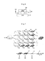
- FIGs. 7 and 8 illustrate a process of manufacturing a BGA package according to a second preferred embodiment.
- the BGA package manufacturing process starts with cutting a green tape wound on a roller 12 in a predetermined size (S71). Then, a green tape 13e positioned at the lowest layer serves as a solder resist substrate and is formed at a thickness of 10 - 100 ⁇ m. The remaining green tapes 13a - 13d except the solder resist substrate are processed and formed as the circuit pattern substrate.
- the green tapes are formed as follows. Glass powder, bonding agent for maintaining viscosity of the glass powder, plasticizer for providing the bonding agent with flexibility so as to prevent the bonding agent from hardening, solvent for dissolving the bonding agent and the plasticizer, and small amounts of additional agents are mixed and dried to form a slurry. After the slurry is dried, it is processed so as to have a predetermined thickness by using a doctor blade technique, so that a green tape is formed. The formed green tape is wound on the roller 12.
- a plurality of via holes 16 are formed in five green tapes 13a - 13e provided at the step S71 by using a mechanical punching technique (S72). Then, the via hole formed in the green tape 13e acts as a guide for exposing the electrode pad formed on any one of the remaining green tapes 13a - 13d to exterior.
- a conductive paste 18 is filled in a via hole 16 of the green tapes 13a - 13d for the substrate and a conductive material 18 is coated in the via hole 16 of the green tape 13e for the solder resist.
- the filled and coated conductive paste 18 is dried (S73).
- the dried conductive paste serves as electrode pads.
- the via hole of the green tapes 13a - 13d for the circuit pattern is completely filled with the conductive paste
- the via hole of the green tape 13e for the solder resist is coated with the conductive paste by a predetermined thickness on its inner wall. Accordingly, the via hole of the green tape 13e still has a predetermined size of hole.
- solder balls are bonded to the electrode pads or the conductive paste throughout a wider area.
- the conductive paste 18 filled in the via hole 16 electrically connects circuit patterns 20 formed on the green tapes 13a - 13d with each other electrically at a post process.
- the conductive paste 18 coated in the via hole of the green tape 13e is connected to an electrode pad that is an input/output pad formed on the green tape 13d for the lowest substrate electrically at a post process.
- the circuit patterns 20 are formed by using a screen printing technique (S74).
- the green tapes 13a - 13e are sequentially aligned so that the green tape 13e for the solder resist is positioned on the lower portion of the green tape 13d for the substrate positioned at the lowest green tape of the green tapes 13a - 3d on which the circuit patterns 20 are formed at the step S74 (S75).
- the five green tapes 13a - 13e are adhered in a stack structure to each other at a laminating process (S76).
- the green tapes 13a - 13e adhered to each other at the step S76 are co-fired with a predetermined heat (S77).
- a predetermined heat S77.
- Each of the green tapes 13a - 13d for the substrate co-fired at the step S77 acts as a ceramic substrate, and the ceramic substrates laminated at the step S47 become a circuit package 65 having a plurality of circuit layers.
- Electronic components 2 including passive elements such as resisters R, inductors L, capacitors C and active elements such as transistors and integrated circuit chip (IC) are mounted on the package 65 provided at the step S77 (S78).
- Material 5 acting as a passivation layer is coated on the entire surface of the package 66 formed at the step S78 (S79).
- each of solder balls 3 is bonded to each of the electrode pads 54 formed on the substrates for the circuit pattern through the via hole 16 formed in the substrate 61 for the solder resist positioned on the lower surface of the package 63 by using a solder ball reflow process (S80).
- the solder balls of the BGA package are bonded to the electrode pad formed on the PCB or the electrode pad formed on the substrate.
- the BGA package 60 may be formed by adding a process of coating an electrode pad on the substrate after plasticizing the laminated substrate.
- the BGA package 60 according to the second embodiment of the present invention includes four green tapes for the substrate but the BGA package is formed by laminating a plurality of green tapes for the substrate depending on circuit configuration to be manufactured.
- FIG. 9 is a cross-sectional view illustrating that the ball grid array package 60 according to the first embodiment of the present invention is mounted on the PCB 51.
- the thickness of the solder resist substrate 61 can be increased by increasing the thickness of the green tape 13e. If the thickness of the substrate 61 of the solder resist is increased, the height of the solder ball 3 formed on the via hole of the substrate 61 for the solder resist increases. As a result, resistance force of the solder ball 3 of the BGA package 60 mounted on the PCB 51 against a shear deformation force (F) 52 exerted by the temperature variation is increased to enhance adhesion with the electrode pad 54.
- F shear deformation force
- the conductive paste 18 coated on the via hole 16 of the solder resist 61 in contact with the solder ball 3 is electrically connected to the electrode pad 54 formed on the substrate so that the electrical adhesion area of the solder ball 3 and the electrode pad 54 is increased.
- the adhesion and adhesion area enhancement between the solder ball 3 and the electrode pad 54 improve the reliability of the BGA package 30.
- solder resists 31 and 61 of the BGA package 30 and 60 according to the embodiments of the present invention are formed of the green tape 12 that is the same material as that used for the substrate, the shrinkages of the substrate and the solder resist are the same, so that crack and distortion of the BGA package that may be caused by the firing process are prevented.
- the green tape 12 is formed with a predetermined thickness by using the above-mentioned doctor blade technique and the via hole of the green tape is formed using the mechanical punching technique, the solder resist is uniform in its thickness and has a uniform area of via hole. Accordingly, the reaction between the BGA package electrode pattern and the firing substrate which was generated during the conventional firing process is prevented.
- the thickness of the solder resist can be freely controlled, the height of the solder ball can be increased. Accordingly, the resistance force against the external shear stress increases.
- the conductive paste coated on the via hole of the solder resist increases the electric adhesion area between the solder ball and the electrode pad. Accordingly, the BGA package according to the embodiments of the present invention has high reliability.
- the solder resist of the BGA package according to the present invention is formed of the green tape whose material is the same as that of the substrate, the BGA package is prevented from being cracked and distorted when being fired.
- the green tape is formed with a predetermined thickness by using the doctor blade technique and the via hole of the green tape is formed using a mechanical punching technique, the solder resist is uniform in its thickness and has a uniform area of via hole. Accordingly, the reaction between the BGA package electrode pattern and the firing substrate which was generated during the conventional firing process is prevented.
- the height of the solder ball can be increased. Accordingly, the resistance force against the external shear stress increases. Since increase in the height of the solder ball increases the cohesion of the solder ball, the resistance force against the external shear deformation force increases. In other words, the deformation of the solder ball is reduced. It enhances the reliability of the BGA package.
- the conductive material coated on the via hole of the solder resist increases the electric adhesion area between solder the ball and the electrode pad. Accordingly, the BGA package has high reliability.
Landscapes
- Engineering & Computer Science (AREA)
- Microelectronics & Electronic Packaging (AREA)
- Power Engineering (AREA)
- Physics & Mathematics (AREA)
- Condensed Matter Physics & Semiconductors (AREA)
- General Physics & Mathematics (AREA)
- Computer Hardware Design (AREA)
- Chemical & Material Sciences (AREA)
- Ceramic Engineering (AREA)
- Manufacturing & Machinery (AREA)
- Electric Connection Of Electric Components To Printed Circuits (AREA)
- Production Of Multi-Layered Print Wiring Board (AREA)
- Wire Bonding (AREA)
Abstract
Description
- The present invention relates to a semiconductor package, and more particularly, to a semiconductor package with a high reliability and fabrication method thereof.
- Recently, as a variety of electronic devices are miniaturized, the circuits for driving these electronic devices are also highly integrated. In other words, circuits and electronic parts are integrated in a single semiconductor package and mounted on printed circuit board (PCB).
- As an example of the semiconductor package, there is a ball grid array (hereafter, referred to as BGA) package in which a plurality of ceramic substrates each having a plurality of circuit patterns are stacked, the substrates are electrically connected to each other through via holes and solder balls are attached to electrode pads.
- FIG. 1 illustrates a process of manufacturing a general ball grid array package. FIG. 2 is a flowchart illustrating a process of manufacturing the general ball grid array package shown in FIG. 1.
- Referring to FIGs. 1 and 2, the fabrication of the BGA package starts with cutting a green tape wound on a
roller 12 in a predetermined size (S21). Here, the green tape is formed as follows. Glass powder, bonding agent for maintaining viscosity of the glass powder, plasticizer for providing the bonding agent with flexibility so as to prevent the bonding agent from hardening, solvent for dissolving the bonding agent and the plasticizer, and small amounts of additional agents are mixed and dried to form slurry. The dried slurry is processed using a tape casting technique to be wound on theroller 12. Necessary substrates are provided by cutting the wound green tape in a predetermined size. - A plurality of
via holes 16 are formed using a mechanical punching technique on fourgreen tapes 13a - 13d provided at the step S21 (S22). - Subsequently, a
conductive paste 18 is filled in thevia hole 16 and the filledconductive paste 18 is dried (S23). Here, the dried conductive paste serves as electrode pads. - The
conductive paste 18 filled in thevia hole 16 connectscircuit patterns 20 formed on thegreen tapes 13a - 13d with each other electrically during a post process. - After the conductive paste is filled in the
via hole 16 at the step S23, thecircuit patterns 20 are formed on thegreen tapes 13a - 13d by using a screen printing technique (S24). - A solder resist is coated on the lowest
green tape 13d on which theelectrode pad 54 is formed among thegreen tapes 13a - 3d on which thecircuit patterns 20 are formed at the step S24 (S25). Here, the solder resist is coated on the entire surface of the lowestgreen tape 13d except theelectrode pad 54. - The remaining
green tapes 13a - 13c are aligned on the lowestgreen tape 13d coated with a solder resist at the step S25 (S26). - If the four
green tapes 13a - 13d are aligned at the step S26, the fourgreen tapes 13a - 13d are stacked and adhered to each other at a laminating process (S27). - The
green tapes 13a - 13d adhered to each other at the step S27 are co-fired with a predetermined heat (S28). Each of thegreen tapes 13a - 13d co-fired at the step S28 acts as a ceramic substrate and the ceramic substrates stacked at the step S28 becomes acircuit package 15 having a plurality of circuit layers. -
Electronic components 2 including passive elements such as resisters R, inductors L, capacitors C and active elements such as transistors and integrated circuit chip (IC) are mounted on thepackage 15 provided at the step S28 (S29). - A
material 5 functioning as a passivation layer is coated on the entire surface of thepackage 6 on which the electronic components are mounted (S30). - Lastly, each of
solder balls 3 is adhered to each of the electrode pads positioned on the lower surface of the coated package 9 by using a solder ball reflow process (S31). - When the
BGA packages 10 manufactured as described above are mounted on a printed circuit board (PCB) or another substrate, the solder ball of the BGA package is adhered to the electrode pad formed on the PCB or the electrode pad formed on the substrate. - Alternatively, if necessary, the
BGA package 10 may be formed by adding a process of coating an electrode pad on the substrate after firing the stacked substrate. - Generally, the
solder resist 1 formed on theBGA package 10 is formed using a screen printing technique on the area which the electrode pads do not exist. - However, in the laminating process in which a predetermined heat and pressure are used and in a firing process, nonuniform coating area and thickness of the solder resist cause the electrode pad to react with a firing substrate and thus damage the electrode. The
solder ball 3 adhered to the electrode pad by a nonuniform solder resist is adhered in nonuniform shape, which deteriorates the reliability of the BGA package. - As shown in FIG. 3, since the solder resist 1 coated on the lowest
green tape 13d slopes slightly, the shape of thesolder ball 3 adhered to the edge of the solder resist 1 also slopes slightly. - The
solder ball 3 is easily deformed by theexternal force 52, as the height of thesolder ball 3 decreases. In other words, as the height of thesolder ball 3 increases, thesolder ball 3 is not easily deformed by the external force. This is because the cohesion of thesolder ball 3 increases. The deformation of the solder ball deteriorates the reliability of the BGA package. - Furthermore,
green tapes 13a - 13g used as a substrate and the solder resist 1 coated on the green tape shrink physicochemically in a firing process. Then, if the shrinkage of thesolder resist 1 is different from that of thegreen tapes 13a - 13g, the BGA package in the firing process is cracked and deformed. To this end, it is necessary to develop a solder resist having the same shrinkage as that of the green tape. - Accordingly, in the conventional BGA package manufacturing method, the BGA package is cracked and deformed since the solder resist made of the material different from that of the substrate and the shrinkage of the substrate is different from that of the solder resist.
- Additionally, in the conventional BGA package manufacturing method, the electrode pad is reacted with a firing substrate and the electrode pad is injured due to nonuniform coating area and nonuniform coating thickness of the solder resist.
- Furthermore, in the conventional BGA package manufacturing method, since cohesion of the solder ball adhered to the electrode pad is decreased due to the solder resist coated on the substrate, the shape of the solder ball is deformed and the solder ball is adhered nonuniformly to deteriorate the reliability of the BGA package.
- Accordingly, the present invention is directed to a semiconductor package and method for packaging a semiconductor that substantially obviates one or more problems due to limitations and disadvantages of the related art.
- It is an object of the present invention to provide a semiconductor package and method for packaging a semiconductor in which crack and distortion of the ball grid array package and damage of electrode pads are prevented to thereby enhance the reliability.
- Additional advantages, objects, and features of the invention will be set forth in part in the description which follows and in part will become apparent to those having ordinary skill in the art upon examination of the following or may be learned from practice of the invention. The objectives and other advantages of the invention may be realized and attained by the structure particularly pointed out in the written description and claims hereof as well as the appended drawings.
- To achieve these objects and other advantages and in accordance with the purpose of the invention, as embodied and broadly described herein, a semiconductor package comprises a first substrate on which a circuit pattern and an electrode pad are formed; a second substrate which is adhered to the first substrate and on which a hole is formed; and a solder ball adhered to the electrode pad through the hole formed on the second substrate.
- The first substrate and the second substrate are formed of same material and the second substrate is thick 10 - 100µm.
- The second substrate can be used as a solder resist.
- In another aspect of the present invention, a method for packaging a semiconductor package comprises the steps of: (a) forming a circuit pattern and an electrode pad on a first substrate; (b) forming a hole on a second substrate; (c) adhering the first substrate to the second substrate; and (d) adhering a solder ball to the electrode pad through the hole formed on the second substrate.
- In another aspect of the present invention, a semiconductor package comprises a first substrate on which a circuit pattern and an electrode pad are formed; a second substrate which is adhered to the first substrate and on which a hole is formed, conductive material being coated on a inner wall of the hole; and a solder ball adhered to the electrode pad through the hole formed on the second substrate.
- The solder ball can be contacted with the electrode pad and the conductive material.
- In another aspect of the present invention, a method for packaging a semiconductor package comprising the steps of: (a) forming a circuit pattern and an electrode pad on a first substrate; (b) forming a hole on a second substrate; (c) coating conductive material on a inner wall of the hole; (d) adhering the first substrate to the second substrate; and (e) adhering a solder ball to the electrode pad through the hole formed on the second substrate.
- It is to be understood that both the foregoing general description and the following detailed description of the present invention are exemplary and explanatory and are intended to provide further explanation of the invention as claimed.
- The accompanying drawings, which are included to provide a further understanding of the invention and are incorporated in and constitute a part of this application, illustrate embodiments of the invention and together with the description serve to explain the principle of the invention. In the drawings:
- FIG. 1 illustrates a process of manufacturing a general ball grid array package;
- FIG. 2 is a flowchart illustrating a process of manufacturing the general ball grid array package shown in FIG. 1;
- FIG. 3 is a cross-sectional view illustrating the ball grid array package shown in FIG. 1;
- FIG. 4 illustrates a process of manufacturing a ball grid array package according to a first preferred embodiment;
- FIG. 5 is a flowchart illustrating a process of manufacturing the ball grid array package shown in FIG. 4;
- FIG. 6 is a cross-sectional view illustrating the ball grid array package shown in FIG. 4;
- FIG. 7 illustrates a process of manufacturing a ball grid array package according to a second preferred embodiment;
- FIG. 8 is a flowchart illustrating a process of manufacturing the ball grid array package shown in FIG. 7; and
- FIG. 9 is a cross-sectional view illustrating the ball grid array package shown in FIG. 7.
-
- Reference will now be made in detail to the preferred embodiments of the present invention, examples of which are illustrated in the accompanying drawings.
- FIGs. 4 and 5 illustrate a process of manufacturing a BGA package according to a first preferred embodiment.
- Referring to FIGs. 4 and 5, the BGA package manufacturing process starts with cutting a green tape wound on a
roller 12 in a predetermined size (S41). Then, thegreen tape 13e positioned at the lowest layer serves as a solder resist substrate and is formed at a thickness of 10 - 100pm. The remaininggreen tapes 13a - 13d except the solder resist substrate are processed and formed as the circuit pattern substrates. Since the circuit pattern substrates and the solder resist substrate are formed of the same material, the BGA package can be prevented from being cracked and being nonuniform when fired. - Here, the green tapes are formed as follows.
- Glass powder, bonding agent for maintaining viscosity of the glass powder, plasticizer for providing the bonding agent with flexibility so as to prevent the bonding agent from hardening, solvent for dissolving the bonding agent and the plasticizer, and small amounts of additional agents are mixed and dried to form a slurry. After the slurry is dried, it is processed to have a predetermined thickness by using a doctor blade technique so that a green tape is formed. The manufactured green tape is wound on the
roller 12. - A plurality of via
holes 16 are formed in fivegreen tapes 13a - 13e provided at the step S41 by using the mechanical punching technique (S42). Then, the via hole 166 formed in thegreen tape 13e acts as a guide for exposing the electrode pad formed on any one of the remaininggreen tapes 13a - 13d to exterior. - Subsequently, a
conductive paste 18 is filled in the viahole 16 of thegreen tapes 13a - 13d for the substrate and the filledconductive paste 18 is dried (S43). Here, the driedconductive paste 18 serves as electrode pads. - At this time, the
conductive paste 18 filled in the viahole 16 functions to electrically connectcircuit patterns 20 formed on thegreen tapes 13a - 13d with each other at a post process. - The
conductive paste 18 is filled in the viahole 16 at the step S43 and each of thecircuit patterns 20 is formed on each of thegreen tapes 13a - 13d for the substrate by using a screen printing technique (S44). - The
green tapes 13a - 13e are sequentially aligned such that thegreen tape 13e for the solder resist is positioned below thegreen tape 13d for the substrate positioned at the lowest layer among thegreen tapes 13a - 13d on which thecircuit patterns 20 are formed at the step S44 (S45). - If the four
green tapes 13a - 13d for the substrate and thegreen tape 13e for the solder resist are aligned in a stack structure at the step S45, the fivegreen tapes 13a - 13e are laminated and adhered to each other at a laminating process (S46). - The
green tapes 13a - 13e adhered to each other at the step S46 are co-fired with a predetermined heat (S47). - Each of the
green tapes 13a - 13d for the substrate co-fired at the step S47 acts as a ceramic substrate and the ceramic substrates laminated at the step S47 become acircuit package 35 having a plurality of circuit layers. -
Electronic components 2 including passive elements such as resisters R, inductors L, capacitors C and active elements such as transistors and integrated circuit chip (IC) are mounted on thepackage 35 provided at the step S47 (S48). - The
material 5 acting as a passivation layer is coated on the entire surface of thepackage 36 formed at the step S48 (S49). - Finally, each of the
solder balls 3 is bonded to each of theelectrode pads 18 formed on the substrates for the circuit pattern through the via hole formed in thesubstrate 31 for the solder resist positioned on the lower surface of thepackage 33 by using a solder ball reflow process (S50). - When the BGA packages 30 manufactured as described above are mounted on a printed circuit board (PCB) or another substrate, the solder balls of the BGA package are bonded to the electrode pad formed on the PCB or the electrode pad formed on the substrate.
- At this time, if necessary, the
BGA package 30 may be formed by adding a process of coating an electrode pad on the substrate after firing the laminated substrate. In addition, theBGA package 30 according to the first embodiment of the present invention includes four green tapes for the substrate but the BGA package is formed by laminating a plurality of green tapes for substrate depending on circuit configuration to be manufactured. - FIG. 6 is a cross-sectional view illustrating that the ball
grid array package 30 according to the first embodiment of the present invention is mounted on the PCB. - Referring to FIG. 6, in the ball
grid array package 30 according to the first embodiment of the present invention, the thickness of the solder resistsubstrate 31 can be increased by increasing the thickness of thegreen tape 13e. If the thickness of the solder resistsubstrate 31 is increased, the height of thesolder ball 3 formed on the via hole of the solder resistsubstrate 31 increases. As a result, resistance force of thesolder ball 3 of theBGA package 30 mounted on thePCB 51 against shear stress (F) 52 exerted by temperature variation is increased to enhance adhesion with theelectrode pad 54. The adhesion enhancement of thesolder ball 3 and theelectrode pad 54 improves the reliability of theBGA package 30. - In addition, since the circuit pattern substrate and the solder resist substrate are formed of the same material, the BGA package can be prevented from being cracked and distorted.
- FIGs. 7 and 8 illustrate a process of manufacturing a BGA package according to a second preferred embodiment.
- Referring to FIGs. 7 and 8, the BGA package manufacturing process starts with cutting a green tape wound on a
roller 12 in a predetermined size (S71). Then, agreen tape 13e positioned at the lowest layer serves as a solder resist substrate and is formed at a thickness of 10 - 100µm. The remaininggreen tapes 13a - 13d except the solder resist substrate are processed and formed as the circuit pattern substrate. - Here, the green tapes are formed as follows. Glass powder, bonding agent for maintaining viscosity of the glass powder, plasticizer for providing the bonding agent with flexibility so as to prevent the bonding agent from hardening, solvent for dissolving the bonding agent and the plasticizer, and small amounts of additional agents are mixed and dried to form a slurry. After the slurry is dried, it is processed so as to have a predetermined thickness by using a doctor blade technique, so that a green tape is formed. The formed green tape is wound on the
roller 12. - A plurality of via
holes 16 are formed in fivegreen tapes 13a - 13e provided at the step S71 by using a mechanical punching technique (S72). Then, the via hole formed in thegreen tape 13e acts as a guide for exposing the electrode pad formed on any one of the remaininggreen tapes 13a - 13d to exterior. - Subsequently, a
conductive paste 18 is filled in a viahole 16 of thegreen tapes 13a - 13d for the substrate and aconductive material 18 is coated in the viahole 16 of thegreen tape 13e for the solder resist. The filled and coatedconductive paste 18 is dried (S73). Here, the dried conductive paste serves as electrode pads. - While the via hole of the
green tapes 13a - 13d for the circuit pattern is completely filled with the conductive paste, the via hole of thegreen tape 13e for the solder resist is coated with the conductive paste by a predetermined thickness on its inner wall. Accordingly, the via hole of thegreen tape 13e still has a predetermined size of hole. - Thus, by coating conductive paste along the inner wall of the via hole for the solder resist 13e, when it is intended to bond solder balls to electrode pads formed on any one of the
green tapes 13a - 13d for the circuit pattern, the solder balls are bonded to the electrode pads or the conductive paste throughout a wider area. - Meanwhile, the
conductive paste 18 filled in the viahole 16 electrically connectscircuit patterns 20 formed on thegreen tapes 13a - 13d with each other electrically at a post process. Theconductive paste 18 coated in the via hole of thegreen tape 13e is connected to an electrode pad that is an input/output pad formed on thegreen tape 13d for the lowest substrate electrically at a post process. - On the
green tapes 13a - 13d in which the conductive paste is filled in the viahole 16 at the step S73, thecircuit patterns 20 are formed by using a screen printing technique (S74). - The
green tapes 13a - 13e are sequentially aligned so that thegreen tape 13e for the solder resist is positioned on the lower portion of thegreen tape 13d for the substrate positioned at the lowest green tape of thegreen tapes 13a - 3d on which thecircuit patterns 20 are formed at the step S74 (S75). - If the four
green tapes 13a - 13d for the substrate and thegreen tape 13e for the solder resist are aligned in a stack structure at the step S75, the fivegreen tapes 13a - 13e are adhered in a stack structure to each other at a laminating process (S76). - The
green tapes 13a - 13e adhered to each other at the step S76 are co-fired with a predetermined heat (S77). Each of thegreen tapes 13a - 13d for the substrate co-fired at the step S77 acts as a ceramic substrate, and the ceramic substrates laminated at the step S47 become acircuit package 65 having a plurality of circuit layers. -
Electronic components 2 including passive elements such as resisters R, inductors L, capacitors C and active elements such as transistors and integrated circuit chip (IC) are mounted on thepackage 65 provided at the step S77 (S78). -
Material 5 acting as a passivation layer is coated on the entire surface of thepackage 66 formed at the step S78 (S79). - Lastly, each of
solder balls 3 is bonded to each of theelectrode pads 54 formed on the substrates for the circuit pattern through the viahole 16 formed in thesubstrate 61 for the solder resist positioned on the lower surface of thepackage 63 by using a solder ball reflow process (S80). - When the BGA packages 60 manufactured as described above is mounted on a printed circuit board (PCB) or another substrate, the solder balls of the BGA package are bonded to the electrode pad formed on the PCB or the electrode pad formed on the substrate.
- Then, if necessary, the
BGA package 60 may be formed by adding a process of coating an electrode pad on the substrate after plasticizing the laminated substrate. In addition, theBGA package 60 according to the second embodiment of the present invention includes four green tapes for the substrate but the BGA package is formed by laminating a plurality of green tapes for the substrate depending on circuit configuration to be manufactured. - FIG. 9 is a cross-sectional view illustrating that the ball
grid array package 60 according to the first embodiment of the present invention is mounted on thePCB 51. - Referring to FIG. 9, in the ball
grid array package 60 according to the second embodiment of the present invention, the thickness of the solder resistsubstrate 61 can be increased by increasing the thickness of thegreen tape 13e. If the thickness of thesubstrate 61 of the solder resist is increased, the height of thesolder ball 3 formed on the via hole of thesubstrate 61 for the solder resist increases. As a result, resistance force of thesolder ball 3 of theBGA package 60 mounted on thePCB 51 against a shear deformation force (F) 52 exerted by the temperature variation is increased to enhance adhesion with theelectrode pad 54. In addition, theconductive paste 18 coated on the viahole 16 of the solder resist 61 in contact with thesolder ball 3 is electrically connected to theelectrode pad 54 formed on the substrate so that the electrical adhesion area of thesolder ball 3 and theelectrode pad 54 is increased. - The adhesion and adhesion area enhancement between the
solder ball 3 and theelectrode pad 54 improve the reliability of theBGA package 30. - As a result, since the solder resists 31 and 61 of the
BGA package green tape 12 that is the same material as that used for the substrate, the shrinkages of the substrate and the solder resist are the same, so that crack and distortion of the BGA package that may be caused by the firing process are prevented. - In addition, since the
green tape 12 is formed with a predetermined thickness by using the above-mentioned doctor blade technique and the via hole of the green tape is formed using the mechanical punching technique, the solder resist is uniform in its thickness and has a uniform area of via hole. Accordingly, the reaction between the BGA package electrode pattern and the firing substrate which was generated during the conventional firing process is prevented. - Also, since the thickness of the solder resist can be freely controlled, the height of the solder ball can be increased. Accordingly, the resistance force against the external shear stress increases.
- The conductive paste coated on the via hole of the solder resist increases the electric adhesion area between the solder ball and the electrode pad. Accordingly, the BGA package according to the embodiments of the present invention has high reliability.
- As described above, the solder resist of the BGA package according to the present invention is formed of the green tape whose material is the same as that of the substrate, the BGA package is prevented from being cracked and distorted when being fired.
- Additionally, since the green tape is formed with a predetermined thickness by using the doctor blade technique and the via hole of the green tape is formed using a mechanical punching technique, the solder resist is uniform in its thickness and has a uniform area of via hole. Accordingly, the reaction between the BGA package electrode pattern and the firing substrate which was generated during the conventional firing process is prevented.
- Also, since the thickness of the solder resist can be freely controlled, the height of the solder ball can be increased. Accordingly, the resistance force against the external shear stress increases. Since increase in the height of the solder ball increases the cohesion of the solder ball, the resistance force against the external shear deformation force increases. In other words, the deformation of the solder ball is reduced. It enhances the reliability of the BGA package. The conductive material coated on the via hole of the solder resist increases the electric adhesion area between solder the ball and the electrode pad. Accordingly, the BGA package has high reliability.
- It will be apparent to those skilled in the art that various modifications and variations can be made in the present invention. Thus, it is intended that the present invention covers the modifications and variations of this invention provided they come within the scope of the appended claims and their equivalents.
Claims (16)
- A semiconductor package comprising:a first substrate on which a circuit pattern and an electrode pad are formed;a second substrate which is adhered to the first substrate and in which a hole is formed; anda solder ball adhered to the electrode pad through the hole formed on the second substrate.
- A semiconductor package, preferably according to claim 1, comprising:a first substrate on which a circuit pattern and an electrode pad are formed;a second substrate which is adhered to the first substrate and on which a hole is formed, conductive material being coated on a inner wall of the hole; anda solder ball adhered to the electrode pad through the hole formed on the second substrate.
- The semiconductor package of claim 1 or 2, wherein the first substrate and the second substrate are formed with a predetermined thickness by using a doctor blade technique.
- The semiconductor package of at least one of the preceding claims, wherein when the first substrate and the second substrate are adhered to each other, the conductive material is connected with the electrode pad electrically.
- The semiconductor package of at least one of the preceding claims, wherein the solder ball is contacted with the electrode pad and the conductive material.
- The semiconductor package of at least one of the preceding claims, wherein the first substrate comprises a plurality of laminated substrates.
- The semiconductor package of at least one of the preceding claims, wherein the first substrate and the second substrate are formed of same material.
- The semiconductor package of at least one of the preceding claims, wherein the second substrate is used as a solder resist that is thick 10 - 100µm.
- A method for packaging a semiconductor package, the method comprising the steps of:(a) forming a circuit pattern and an electrode pad on a first substrate;(b) forming a hole on a second substrate;(c) adhering the first substrate to the second substrate; and(d) adhering a solder ball to the electrode pad through the hole formed on the second substrate.
- A method for packaging a semiconductor package, preferably according to claim 9, the method comprising the steps of:(a) forming a circuit pattern and an electrode pad on a first substrate;(b) forming a hole on a second substrate;(c) coating conductive material on a inner wall of the hole;(d) adhering the first substrate to the second substrate; and(e) adhering a solder ball to the electrode pad through the hole formed on the second substrate.
- The method of claim 9 or 10, wherein the hole formed on the second substrate is a guide for exposing the electrode pad formed on the first substrate to exterior.
- The method of at least one of claims 9 to 11, wherein the first substrate comprises a plurality of laminated substrates.
- The method of at least one of claims 9 to 12, wherein when the first substrate and the second substrate are adhered to each other, the conductive material is connected with the electrode pad electrically.
- The method of at least one of claims 9 to 13, wherein the solder ball is contacted with the electrode pad and the conductive material.
- The method of at least one of claims 9 to 14, wherein the first substrate and the second substrate are formed of same material.
- The method of at least one of claims 9 to 15, wherein the second substrate is used as a solder resist that is thick 10 - 100µm.
Applications Claiming Priority (2)
| Application Number | Priority Date | Filing Date | Title |
|---|---|---|---|
| KR10-2002-0031981A KR100481216B1 (en) | 2002-06-07 | 2002-06-07 | Ball Grid Array Package And Method Of Fabricating The Same |
| KR2002031981 | 2002-06-07 |
Publications (2)
| Publication Number | Publication Date |
|---|---|
| EP1369921A2 true EP1369921A2 (en) | 2003-12-10 |
| EP1369921A3 EP1369921A3 (en) | 2006-02-01 |
Family
ID=29546399
Family Applications (1)
| Application Number | Title | Priority Date | Filing Date |
|---|---|---|---|
| EP03012778A Withdrawn EP1369921A3 (en) | 2002-06-07 | 2003-06-05 | Semiconductor package and method for packaging a semiconductor |
Country Status (4)
| Country | Link |
|---|---|
| US (1) | US7564131B2 (en) |
| EP (1) | EP1369921A3 (en) |
| KR (1) | KR100481216B1 (en) |
| CN (1) | CN100409429C (en) |
Citations (4)
| Publication number | Priority date | Publication date | Assignee | Title |
|---|---|---|---|---|
| US5636104A (en) * | 1995-05-31 | 1997-06-03 | Samsung Electronics Co., Ltd. | Printed circuit board having solder ball mounting groove pads and a ball grid array package using such a board |
| EP0786808A1 (en) * | 1996-01-19 | 1997-07-30 | Shinko Electric Industries Co. Ltd. | Anisotropic conductive sheet and printed circuit board |
| EP0814643A2 (en) * | 1996-06-19 | 1997-12-29 | Ibiden Co, Ltd. | Multilayer printed circuit board |
| US5763059A (en) * | 1995-03-31 | 1998-06-09 | Kyocera Corporation | Circuit board |
Family Cites Families (56)
| Publication number | Priority date | Publication date | Assignee | Title |
|---|---|---|---|---|
| JPS5824037B2 (en) * | 1980-05-26 | 1983-05-18 | 富士通株式会社 | Conductor ball arrangement method |
| JPH0736428B2 (en) * | 1989-03-22 | 1995-04-19 | 株式会社村田製作所 | Ceramic substrate |
| US5111278A (en) * | 1991-03-27 | 1992-05-05 | Eichelberger Charles W | Three-dimensional multichip module systems |
| US5401911A (en) * | 1992-04-03 | 1995-03-28 | International Business Machines Corporation | Via and pad structure for thermoplastic substrates and method and apparatus for forming the same |
| JPH0613755A (en) * | 1992-06-29 | 1994-01-21 | Hitachi Ltd | Ceramic multilayer wiring board and manufacture thereof |
| US5442852A (en) * | 1993-10-26 | 1995-08-22 | Pacific Microelectronics Corporation | Method of fabricating solder ball array |
| JP2606110B2 (en) * | 1993-12-15 | 1997-04-30 | 日本電気株式会社 | Multilayer substrate and method of manufacturing the same |
| US5497938A (en) * | 1994-09-01 | 1996-03-12 | Intel Corporation | Tape with solder forms and methods for transferring solder to chip assemblies |
| US5663593A (en) * | 1995-10-17 | 1997-09-02 | National Semiconductor Corporation | Ball grid array package with lead frame |
| KR970024051A (en) * | 1995-10-25 | 1997-05-30 | 김광호 | Semiconductor Package Manufacturing Method |
| US6072236A (en) * | 1996-03-07 | 2000-06-06 | Micron Technology, Inc. | Micromachined chip scale package |
| JPH10112514A (en) | 1996-10-04 | 1998-04-28 | Toshiba Corp | Semiconductor device and its manufacture |
| JP3576727B2 (en) * | 1996-12-10 | 2004-10-13 | 株式会社デンソー | Surface mount type package |
| US5952840A (en) * | 1996-12-31 | 1999-09-14 | Micron Technology, Inc. | Apparatus for testing semiconductor wafers |
| AU5496098A (en) * | 1997-01-23 | 1998-08-18 | Seiko Epson Corporation | Film carrier tape, semiconductor assembly, semiconductor device, manufacturing method therefor, mounting board, and electronic equipment |
| JP3173410B2 (en) * | 1997-03-14 | 2001-06-04 | 松下電器産業株式会社 | Package substrate and method of manufacturing the same |
| US7007833B2 (en) * | 1997-05-27 | 2006-03-07 | Mackay John | Forming solder balls on substrates |
| KR19990005679A (en) * | 1997-06-30 | 1999-01-25 | 이형도 | Manufacturing method of package for flip chip mounting |
| DE1025587T1 (en) * | 1997-07-21 | 2001-02-08 | Aguila Technologies, Inc. | SEMICONDUCTOR FLIPCHIP PACK AND PRODUCTION METHOD THEREFOR |
| US6683384B1 (en) * | 1997-10-08 | 2004-01-27 | Agere Systems Inc | Air isolated crossovers |
| US6137062A (en) * | 1998-05-11 | 2000-10-24 | Motorola, Inc. | Ball grid array with recessed solder balls |
| JP3825181B2 (en) * | 1998-08-20 | 2006-09-20 | 沖電気工業株式会社 | Semiconductor device manufacturing method and semiconductor device |
| US6400018B2 (en) * | 1998-08-27 | 2002-06-04 | 3M Innovative Properties Company | Via plug adapter |
| US6187418B1 (en) * | 1999-07-19 | 2001-02-13 | International Business Machines Corporation | Multilayer ceramic substrate with anchored pad |
| US6295730B1 (en) * | 1999-09-02 | 2001-10-02 | Micron Technology, Inc. | Method and apparatus for forming metal contacts on a substrate |
| EP2265101B1 (en) * | 1999-09-02 | 2012-08-29 | Ibiden Co., Ltd. | Printed circuit board and method of manufacturing printed circuit board |
| JP3865989B2 (en) * | 2000-01-13 | 2007-01-10 | 新光電気工業株式会社 | Multilayer wiring board, wiring board, multilayer wiring board manufacturing method, wiring board manufacturing method, and semiconductor device |
| US6909054B2 (en) * | 2000-02-25 | 2005-06-21 | Ibiden Co., Ltd. | Multilayer printed wiring board and method for producing multilayer printed wiring board |
| JP3882500B2 (en) * | 2000-03-02 | 2007-02-14 | 株式会社村田製作所 | Thick film insulating composition, ceramic electronic component using the same, and electronic device |
| JP3407716B2 (en) * | 2000-06-08 | 2003-05-19 | 株式会社村田製作所 | Composite laminated electronic components |
| JP2001358445A (en) * | 2000-06-13 | 2001-12-26 | Denso Corp | Mount structure of electronic component |
| US6459039B1 (en) * | 2000-06-19 | 2002-10-01 | International Business Machines Corporation | Method and apparatus to manufacture an electronic package with direct wiring pattern |
| US6459150B1 (en) * | 2000-08-17 | 2002-10-01 | Industrial Technology Research Institute | Electronic substrate having an aperture position through a substrate, conductive pads, and an insulating layer |
| US6408511B1 (en) * | 2000-08-21 | 2002-06-25 | National Semiconductor, Inc. | Method of creating an enhanced BGA attachment in a low-temperature co-fired ceramic (LTCC) substrate |
| DE10065895C1 (en) * | 2000-11-17 | 2002-05-23 | Infineon Technologies Ag | Electronic component used as an integrated circuit comprises a screen for electromagnetic scattering, a semiconductor chip made from a semiconductor substrate and an electrically conducting trenched layer |
| DE10104574A1 (en) * | 2001-02-01 | 2002-08-08 | Epcos Ag | Electrical component substrate and manufacturing method |
| JP4724924B2 (en) * | 2001-02-08 | 2011-07-13 | ソニー株式会社 | Manufacturing method of display device |
| US6417025B1 (en) * | 2001-04-02 | 2002-07-09 | Alien Technology Corporation | Integrated circuit packages assembled utilizing fluidic self-assembly |
| US6692818B2 (en) * | 2001-06-07 | 2004-02-17 | Matsushita Electric Industrial Co., Ltd. | Method for manufacturing circuit board and circuit board and power conversion module using the same |
| TW552832B (en) * | 2001-06-07 | 2003-09-11 | Lg Electronics Inc | Hole plugging method for printed circuit boards, and hole plugging device |
| US6649507B1 (en) * | 2001-06-18 | 2003-11-18 | Taiwan Semiconductor Manufacturing Company | Dual layer photoresist method for fabricating a mushroom bumping plating structure |
| US6668449B2 (en) * | 2001-06-25 | 2003-12-30 | Micron Technology, Inc. | Method of making a semiconductor device having an opening in a solder mask |
| CN101024315A (en) * | 2001-07-06 | 2007-08-29 | 钟渊化学工业株式会社 | Laminate and its producing method |
| US6676784B2 (en) * | 2001-07-17 | 2004-01-13 | International Business Machines Corporation | Process for the manufacture of multilayer ceramic substrates |
| TW578910U (en) * | 2003-05-21 | 2004-03-01 | Mjc Probe Inc | Integrated circuit probe card |
| US6605524B1 (en) * | 2001-09-10 | 2003-08-12 | Taiwan Semiconductor Manufacturing Company | Bumping process to increase bump height and to create a more robust bump structure |
| DE10164494B9 (en) * | 2001-12-28 | 2014-08-21 | Epcos Ag | Encapsulated low-profile device and method of manufacture |
| TWI245402B (en) * | 2002-01-07 | 2005-12-11 | Megic Corp | Rod soldering structure and manufacturing process thereof |
| SG104293A1 (en) * | 2002-01-09 | 2004-06-21 | Micron Technology Inc | Elimination of rdl using tape base flip chip on flex for die stacking |
| US6965168B2 (en) * | 2002-02-26 | 2005-11-15 | Cts Corporation | Micro-machined semiconductor package |
| US6975035B2 (en) * | 2002-03-04 | 2005-12-13 | Micron Technology, Inc. | Method and apparatus for dielectric filling of flip chip on interposer assembly |
| SG115455A1 (en) * | 2002-03-04 | 2005-10-28 | Micron Technology Inc | Methods for assembly and packaging of flip chip configured dice with interposer |
| SG115459A1 (en) * | 2002-03-04 | 2005-10-28 | Micron Technology Inc | Flip chip packaging using recessed interposer terminals |
| US6796637B2 (en) * | 2002-05-28 | 2004-09-28 | Ngk Insulators, Ltd. | Piezoelectric/electrostrictive film type actuator and method for manufacturing the same |
| JP2004014854A (en) * | 2002-06-07 | 2004-01-15 | Shinko Electric Ind Co Ltd | Semiconductor device |
| US6762503B2 (en) * | 2002-08-29 | 2004-07-13 | Micron Technology, Inc. | Innovative solder ball pad structure to ease design rule, methods of fabricating same and substrates, electronic device assemblies and systems employing same |
-
2002
- 2002-06-07 KR KR10-2002-0031981A patent/KR100481216B1/en not_active IP Right Cessation
-
2003
- 2003-06-04 US US10/453,503 patent/US7564131B2/en not_active Expired - Fee Related
- 2003-06-05 EP EP03012778A patent/EP1369921A3/en not_active Withdrawn
- 2003-06-07 CN CNB031546064A patent/CN100409429C/en not_active Expired - Fee Related
Patent Citations (4)
| Publication number | Priority date | Publication date | Assignee | Title |
|---|---|---|---|---|
| US5763059A (en) * | 1995-03-31 | 1998-06-09 | Kyocera Corporation | Circuit board |
| US5636104A (en) * | 1995-05-31 | 1997-06-03 | Samsung Electronics Co., Ltd. | Printed circuit board having solder ball mounting groove pads and a ball grid array package using such a board |
| EP0786808A1 (en) * | 1996-01-19 | 1997-07-30 | Shinko Electric Industries Co. Ltd. | Anisotropic conductive sheet and printed circuit board |
| EP0814643A2 (en) * | 1996-06-19 | 1997-12-29 | Ibiden Co, Ltd. | Multilayer printed circuit board |
Also Published As
| Publication number | Publication date |
|---|---|
| KR100481216B1 (en) | 2005-04-08 |
| CN1487582A (en) | 2004-04-07 |
| US7564131B2 (en) | 2009-07-21 |
| CN100409429C (en) | 2008-08-06 |
| US20030227083A1 (en) | 2003-12-11 |
| KR20030094718A (en) | 2003-12-18 |
| EP1369921A3 (en) | 2006-02-01 |
Similar Documents
| Publication | Publication Date | Title |
|---|---|---|
| US7674362B2 (en) | Method for fabrication of a conductive bump structure of a circuit board | |
| US7550315B2 (en) | Method for fabricating semiconductor package with multi-layer die contact and external contact | |
| US7102230B2 (en) | Circuit carrier and fabrication method thereof | |
| US5777387A (en) | Semiconductor device constructed by mounting a semiconductor chip on a film carrier tape | |
| US20100255634A1 (en) | Manufacturing method of bottom substrate of package | |
| US6627979B2 (en) | Semiconductor package and fabrication method of the same | |
| US20080151518A1 (en) | Circuit board structure with embedded electronic components | |
| KR20000057332A (en) | Chip scale ball grid array for integrated circuit package | |
| JP3450236B2 (en) | Semiconductor device and manufacturing method thereof | |
| US6969674B2 (en) | Structure and method for fine pitch flip chip substrate | |
| US20010018231A1 (en) | Bumpless flip chip assembly with strips and via-fill | |
| US6596620B2 (en) | BGA substrate via structure | |
| KR20000041683A (en) | Method for fabricating printed circuit board | |
| US20040106288A1 (en) | Method for manufacturing circuit devices | |
| EP1232677B1 (en) | Flip chip package, circuit board thereof and packaging method thereof | |
| TWI395318B (en) | Thin stack package using embedded-type chip carrier | |
| EP1369921A2 (en) | Semiconductor package and method for packaging a semiconductor | |
| KR100650728B1 (en) | stacked package and method for manufacturing the same | |
| EP1848029B1 (en) | Carrying structure of electronic components | |
| JP3781998B2 (en) | Manufacturing method of stacked semiconductor device | |
| JP3780688B2 (en) | CSP substrate manufacturing method | |
| KR20050081472A (en) | Ball grid array package and method of fabricating the same | |
| JP2001257229A (en) | Electronic part with bump and method of mounting the same | |
| JP2006310543A (en) | Wiring board and its production process, wiring board with semiconductor circuit element | |
| KR20020028473A (en) | Stack package |
Legal Events
| Date | Code | Title | Description |
|---|---|---|---|
| PUAI | Public reference made under article 153(3) epc to a published international application that has entered the european phase |
Free format text: ORIGINAL CODE: 0009012 |
|
| AK | Designated contracting states |
Kind code of ref document: A2 Designated state(s): AT BE BG CH CY CZ DE DK EE ES FI FR GB GR HU IE IT LI LU MC NL PT RO SE SI SK TR |
|
| AX | Request for extension of the european patent |
Extension state: AL LT LV MK |
|
| PUAL | Search report despatched |
Free format text: ORIGINAL CODE: 0009013 |
|
| AK | Designated contracting states |
Kind code of ref document: A3 Designated state(s): AT BE BG CH CY CZ DE DK EE ES FI FR GB GR HU IE IT LI LU MC NL PT RO SE SI SK TR |
|
| AX | Request for extension of the european patent |
Extension state: AL LT LV MK |
|
| 17P | Request for examination filed |
Effective date: 20060419 |
|
| AKX | Designation fees paid |
Designated state(s): DE FR GB NL |
|
| STAA | Information on the status of an ep patent application or granted ep patent |
Free format text: STATUS: THE APPLICATION IS DEEMED TO BE WITHDRAWN |
|
| 18D | Application deemed to be withdrawn |
Effective date: 20081231 |