EP1369685A2 - Capteur de gaz avec de courtes connexions à un connecteur, qui contient un circuit de traitement de signaux, pour minimiser le brouillage - Google Patents
Capteur de gaz avec de courtes connexions à un connecteur, qui contient un circuit de traitement de signaux, pour minimiser le brouillage Download PDFInfo
- Publication number
- EP1369685A2 EP1369685A2 EP03018575A EP03018575A EP1369685A2 EP 1369685 A2 EP1369685 A2 EP 1369685A2 EP 03018575 A EP03018575 A EP 03018575A EP 03018575 A EP03018575 A EP 03018575A EP 1369685 A2 EP1369685 A2 EP 1369685A2
- Authority
- EP
- European Patent Office
- Prior art keywords
- sensor
- gas concentration
- cell
- pump cell
- nox
- Prior art date
- Legal status (The legal status is an assumption and is not a legal conclusion. Google has not performed a legal analysis and makes no representation as to the accuracy of the status listed.)
- Ceased
Links
- 239000004020 conductor Substances 0.000 title abstract description 22
- 238000012545 processing Methods 0.000 title abstract description 19
- 239000007789 gas Substances 0.000 claims description 121
- 229910052760 oxygen Inorganic materials 0.000 claims description 17
- 239000001301 oxygen Substances 0.000 claims description 17
- QVGXLLKOCUKJST-UHFFFAOYSA-N atomic oxygen Chemical compound [O] QVGXLLKOCUKJST-UHFFFAOYSA-N 0.000 claims description 15
- 239000007784 solid electrolyte Substances 0.000 claims description 6
- 238000004891 communication Methods 0.000 claims description 4
- 238000000034 method Methods 0.000 claims description 3
- MWUXSHHQAYIFBG-UHFFFAOYSA-N Nitric oxide Chemical compound O=[N] MWUXSHHQAYIFBG-UHFFFAOYSA-N 0.000 description 171
- 239000000446 fuel Substances 0.000 description 13
- 238000012937 correction Methods 0.000 description 6
- 238000004519 manufacturing process Methods 0.000 description 6
- BASFCYQUMIYNBI-UHFFFAOYSA-N platinum Chemical compound [Pt] BASFCYQUMIYNBI-UHFFFAOYSA-N 0.000 description 6
- CPLXHLVBOLITMK-UHFFFAOYSA-N Magnesium oxide Chemical compound [Mg]=O CPLXHLVBOLITMK-UHFFFAOYSA-N 0.000 description 4
- 239000000919 ceramic Substances 0.000 description 4
- 238000000354 decomposition reaction Methods 0.000 description 4
- 238000005259 measurement Methods 0.000 description 4
- PNEYBMLMFCGWSK-UHFFFAOYSA-N aluminium oxide Inorganic materials [O-2].[O-2].[O-2].[Al+3].[Al+3] PNEYBMLMFCGWSK-UHFFFAOYSA-N 0.000 description 3
- 238000002485 combustion reaction Methods 0.000 description 3
- 238000010586 diagram Methods 0.000 description 3
- 238000003475 lamination Methods 0.000 description 3
- 229910000510 noble metal Inorganic materials 0.000 description 3
- VYPSYNLAJGMNEJ-UHFFFAOYSA-N Silicium dioxide Chemical compound O=[Si]=O VYPSYNLAJGMNEJ-UHFFFAOYSA-N 0.000 description 2
- MCMNRKCIXSYSNV-UHFFFAOYSA-N Zirconium dioxide Chemical compound O=[Zr]=O MCMNRKCIXSYSNV-UHFFFAOYSA-N 0.000 description 2
- 230000003213 activating effect Effects 0.000 description 2
- WMWLMWRWZQELOS-UHFFFAOYSA-N bismuth(iii) oxide Chemical compound O=[Bi]O[Bi]=O WMWLMWRWZQELOS-UHFFFAOYSA-N 0.000 description 2
- 230000003197 catalytic effect Effects 0.000 description 2
- 230000001276 controlling effect Effects 0.000 description 2
- 238000009434 installation Methods 0.000 description 2
- 239000000395 magnesium oxide Substances 0.000 description 2
- 239000000203 mixture Substances 0.000 description 2
- -1 oxygen ion Chemical class 0.000 description 2
- 230000002093 peripheral effect Effects 0.000 description 2
- 229910052697 platinum Inorganic materials 0.000 description 2
- 239000000758 substrate Substances 0.000 description 2
- 238000009966 trimming Methods 0.000 description 2
- 229910004369 ThO2 Inorganic materials 0.000 description 1
- 230000005540 biological transmission Effects 0.000 description 1
- ODINCKMPIJJUCX-UHFFFAOYSA-N calcium oxide Inorganic materials [Ca]=O ODINCKMPIJJUCX-UHFFFAOYSA-N 0.000 description 1
- 239000003990 capacitor Substances 0.000 description 1
- 239000011195 cermet Substances 0.000 description 1
- 239000003795 chemical substances by application Substances 0.000 description 1
- 239000002131 composite material Substances 0.000 description 1
- 230000003247 decreasing effect Effects 0.000 description 1
- 238000013461 design Methods 0.000 description 1
- 238000001514 detection method Methods 0.000 description 1
- 230000006866 deterioration Effects 0.000 description 1
- KZHJGOXRZJKJNY-UHFFFAOYSA-N dioxosilane;oxo(oxoalumanyloxy)alumane Chemical compound O=[Si]=O.O=[Si]=O.O=[Al]O[Al]=O.O=[Al]O[Al]=O.O=[Al]O[Al]=O KZHJGOXRZJKJNY-UHFFFAOYSA-N 0.000 description 1
- 230000000694 effects Effects 0.000 description 1
- 230000005672 electromagnetic field Effects 0.000 description 1
- CJNBYAVZURUTKZ-UHFFFAOYSA-N hafnium(IV) oxide Inorganic materials O=[Hf]=O CJNBYAVZURUTKZ-UHFFFAOYSA-N 0.000 description 1
- 238000009413 insulation Methods 0.000 description 1
- 238000012986 modification Methods 0.000 description 1
- 230000004048 modification Effects 0.000 description 1
- 229910052863 mullite Inorganic materials 0.000 description 1
- 238000013021 overheating Methods 0.000 description 1
- 230000001105 regulatory effect Effects 0.000 description 1
- 239000000377 silicon dioxide Substances 0.000 description 1
- 229910052596 spinel Inorganic materials 0.000 description 1
- 239000011029 spinel Substances 0.000 description 1
- ZCUFMDLYAMJYST-UHFFFAOYSA-N thorium dioxide Chemical compound O=[Th]=O ZCUFMDLYAMJYST-UHFFFAOYSA-N 0.000 description 1
- XLYOFNOQVPJJNP-UHFFFAOYSA-N water Substances O XLYOFNOQVPJJNP-UHFFFAOYSA-N 0.000 description 1
- FIXNOXLJNSSSLJ-UHFFFAOYSA-N ytterbium(III) oxide Inorganic materials O=[Yb]O[Yb]=O FIXNOXLJNSSSLJ-UHFFFAOYSA-N 0.000 description 1
- RUDFQVOCFDJEEF-UHFFFAOYSA-N yttrium(III) oxide Inorganic materials [O-2].[O-2].[O-2].[Y+3].[Y+3] RUDFQVOCFDJEEF-UHFFFAOYSA-N 0.000 description 1
Images


Classifications
-
- G—PHYSICS
- G01—MEASURING; TESTING
- G01N—INVESTIGATING OR ANALYSING MATERIALS BY DETERMINING THEIR CHEMICAL OR PHYSICAL PROPERTIES
- G01N27/00—Investigating or analysing materials by the use of electric, electrochemical, or magnetic means
- G01N27/26—Investigating or analysing materials by the use of electric, electrochemical, or magnetic means by investigating electrochemical variables; by using electrolysis or electrophoresis
- G01N27/403—Cells and electrode assemblies
- G01N27/406—Cells and probes with solid electrolytes
- G01N27/4067—Means for heating or controlling the temperature of the solid electrolyte
Definitions
- the present invention relates generally to a gas concentration measuring apparatus for measuring the concentration of gases which may be employed in an air-fuel ratio control system for automotive vehicles, and more particularly to a gas concentration measuring apparatus designed to minimize an error component contained in an output thereof.
- NOx sensors designed to measure the concentration of nitrogen oxide (NOx) contained in exhaust emissions of automotive engines are proposed and put into practical use.
- a gas sensor which is designed to measure the concentrations of NOx and O 2 contained in exhaust gasses of the engine simultaneously.
- This type of gas sensor includes a pump cell for decomposing or ionizing oxygen molecules contained in exhaust gasses to measure the concentration of O 2 and a sensor cell for decomposing NOx in the oxygen-decomposed exhaust gasses to measure the concentration of NOx.
- the measurement of the concentration of each of NOx and O 2 is achieved by applying a given voltage to a corresponding one of the pump cell and the sensor cell to induce flow of current as a function of one of the concentrations of NOx and O 2 .
- the current is outputted from the gas sensor and converted into a voltage signal which is, in turn, used in, for example, an engine control unit of the vehicle.
- the above gas sensor however, has the drawback in that the amount of current flowing through the cell sensor as a function of the concentration of NOx is extremely small, so that it apt to interfere with electrical noises, resulting in a failure in measuring the concentration of NOx accurately. Specifically, when the concentration of NOx is within 0 to 2000ppm, a current output from the sensor cell is as little as 5 to 10 ⁇ A. Therefore, in the case where the gas sensor is used in an engine control system of an automotive vehicle, signal outputs from peripheral electrical devices are added to an output of the gas sensor as noises which will produce an error in measuring the concentration of NOx.
- a gas concentration measuring apparatus includes: (a) a gas concentration sensor outputting a signal as a function of concentration of a given component of gasses; (b) a signal processing circuit processing the signal outputted from the gas concentration sensor to produce a voltage signal indicative of the concentration of the given component of the gasses; and (c) a conductor electrically connecting the gas concentration sensor and the signal processing circuit for transmission of the signal.
- the conductor has a length which is determined as a function of a level of the signal outputted from the gas concentration sensor. The weaker the level of the signal is, the shorter the length of the conductor.
- a connector which connects the gas concentration sensor with an external device.
- the connector has disposed therein the signal processing circuit.
- An impedance measuring circuit which measures the impedance of a sensor element of the gas concentration sensor.
- the impedance measuring circuit is integrated in a single unit together with the signal processing circuit.
- a heater and a heater control circuit are provided.
- the heater heats up a sensor element of the gas concentration sensor.
- the heater control circuit controls a power supply to the heater.
- the heater control circuit is integrated in a single unit together with the signal processing circuit.
- the gas concentration measuring apparatus may be mounted in a vehicle to measure, for example, the concentrations of O 2 and NOx contained in exhaust emissions of a combustion engine for use in an air-fuel ratio control.
- the gas concentration sensor includes a first cell responsive to application of a voltage to discharge oxygen contained in the gasses outside the gas concentration sensor, producing a first electric current as a function of concentration of the discharged oxygen and a second cell responsive to application of a voltage to produce a second electric current as a function of concentration of a specified gas component contained in the gasses from which the oxygen is discharged by the first cell.
- the signal processing circuit has a function of compensating for a unit-to-unit variation in characteristic of the gas concentration sensor.
- the signal processing circuit corrects an output characteristic of the gas concentration sensor so as to agree with a desired one.
- the impedance measuring circuit has a function of compensating for a unit-to-unit variation in characteristic of the gas concentration sensor.
- the impedance measuring circuit produces an impedance signal indicative of the impedance of the sensor element of the gas concentration sensor and corrects the impedance signal so as to eliminate a variation in the impedance signal caused by the unit-to-unit variation in characteristic of the gas concentration sensor.
- the heater control circuit connects with the heater through a power supply conductor for supplying the power to the heater.
- the heater control circuit has a function of minimizing an error component caused by a resistance value of the power supply conductor.
- the signal processing circuit, the impedance measuring circuit, and the heater control circuit are formed on a bare chip mounted on a ceramic substrate.
- a gas concentration measuring apparatus which comprises: (a) a gas concentration sensor outputting a signal as a function of concentration of a given component of gasses; (b) a signal processing circuit processing the signal outputted from the gas concentration sensor to provide a voltage signal indicative of the concentration of the given component of the gasses; and (c) a connector having disposed therein the signal processing circuit, the connector having a first end coupled to the signal processing circuit and a second end providing electrical connection with an external device to transmit the voltage signal to the external device.
- a gas concentration measuring apparatus which is used with, as one example, an automotive engine control system designed to control the quantity of fuel injected into an internal combustion engine as a function of an output of the gas concentration measuring apparatus under feedback (F/B) control to bring the air-fuel (A/F) ratio into agreement with a target value and to diagnose the deterioration of a catalytic converter installed in an exhaust pipe of the engine.
- F/B feedback-fuel
- the gas concentration measuring apparatus uses a composite gas concentration sensor 100 capable of measuring concentrations of oxygen (O 2 ) and nitrogen oxide (NOx) contained in exhaust gasses of a multi-cylinder four-cycle engine simultaneously.
- a fuel injector 12 is installed in an intake pipe 11 to supply the fuel to the engine 10.
- the gas concentration sensor 100 is installed in an exhaust pipe 13 and outputs sensor signals indicative of the concentration of O 2 and NOx.
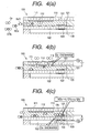
- the gas concentration sensor 100 has, as shown in Fig. 3, a two-cell structure designed to measure the concentrations of O 2 and NOx contained in exhaust gasses of the engine 10 simultaneously.
- the gas concentration sensor 100 is made of a lamination of the pump cell 110, the sensor cell 120, a porous diffused layer 101, an air duct 102, an insulating layer 104, and a heater 103.
- the gas concentration sensor 100 is installed at the right side thereof, as viewed in the drawing, on the exhaust pipe 13 of the engine so as to expose upper, lower, and left surfaces to exhaust gasses.
- the pump cell 110 is disposed on the porous diffused layer 101 so that it is exposed to the exhaust gasses.
- a first pump cell electrode 111 is mounted on the upper surface of the pump cell 110.
- a second pump cell electrode 112 is mounted on the lower surface of the pump cell 110 facing the porous diffused layer 101.
- the sensor cell 120 is interposed between the porous diffused layer 101 and the air duct 102.
- a first sensor cell electrode 121 is attached to an upper surface of the sensor cell 120 facing the porous diffused layer 101.
- a second sensor cell electrode 122 is attached to a lower surface of the sensor cell 120 facing the air duct 102.
- the exhaust gasses enters the porous diffused layer 101 from the left side thereof, as viewed in the drawing, and flow in the right direction.
- the pump cell 110 and the sensor cell 120 are each formed with a solid electrolyte lamination such as an oxygen ion conductive oxide sintered member made from ZrO 2 , HfO 2 , ThO 2 , and Bi 2 O 3 in which CaO, MgO, Y 2 O 3 , and Yb 2 O 3 are solved as fixing agents.
- the porous diffused layer 101 is made of a heat-resisting inorganic matter such as alumina, magnesia, silica, spinel, and mullite.
- the first pump cell electrode 111 and the first and second sensor cell electrodes 121 and 122 are each made of a noble metal with a high catalytic activity such as platinum (Pt), while the second pump electrode 112 is made of a noble metal such as Au-Pt which is inactive with respect to NOx, that is, hardly decomposes NOx.
- a noble metal with a high catalytic activity such as platinum (Pt)
- the second pump electrode 112 is made of a noble metal such as Au-Pt which is inactive with respect to NOx, that is, hardly decomposes NOx.
- the heater 103 is embedded in the insulating layer 104.
- the insulating layer 104 defines the air duct 102 between itself and the sensor cell 120.
- the air duct 102 serves as a reference gas chamber into which the air is introduced.
- the air in the reference gas chamber is used as a reference gas in measuring the concentration of O 2 .
- the insulating layer 104 is made of alumina.
- the heater 103 is made of platinum and cermet such as alumina and supplied with power from a heater control circuit, as will be described later in detail, to produce the heat for activating the whole of the gas concentration sensor 100.
- the O 2 molecules in the exhaust gasses are usually not decomposed by the pump cell 110 completely, so that residual O 2 molecules reach the sensor cell 120.
- the application of voltage to the sensor cell 120 causes the first sensor cell electrode 121 to decompose the O 2 and NOx molecules, as shown in Fig. 4(c), so that oxygen ions are discharged to the air duct 102 through the second sensor cell electrode 122, thereby causing a limiting current (also referred to as a sensor cell current or a NOx current below) to flow through the sensor cell 120 as a function of the concentration of NOx.
- a limiting current also referred to as a sensor cell current or a NOx current below
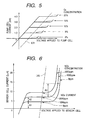
- Fig. 5 shows a V-I relation between the voltage applied to the pump cell 110 and the pump cell current (mA) outputted from the pump cell 110.
- Straight segments of lines extending parallel to the abscissa axis indicate limiting current measurable ranges, respectively, which are shifted to the positive side of voltage applied to the pump cell 110 as the concentration of O 2 increases. Therefore, if the voltage applied to the pump cell 110 is kept constant when the concentration of O 2 is changing, the concentration of O 2 may exceed a corresponding one of the limiting current measurable ranges, resulting in difficulty in measuring the concentration of O 2 accurately.
- the voltage to be applied to the pump cell 110 is regulated so that it changes at a rate equivalent to a rate of change in dc resistance component of the pump cell 110 as a function of the voltage applied to the pump cell 110. Specifically, the voltage to be applied to the pump cell 110 is changed along a broken line LX1 so that an output of the pump cell 110 may fall within any one of the limiting current measurable ranges at all the time regardless of the concentration of O 2 in the exhaust gasses.
- Fig. 6 shows a V-I relation between the voltage applied to the sensor cell 120 and the sensor cell current (mA) outputted from the sensor cell 120.
- a current as indicated by A1
- a current as indicated by A2
- A2 a current, as indicated by A2 , produced by the decomposition of NOx by the sensor cell 120 is also outputted from the sensor cell 120.
- the voltage applied to the sensor cell 120 exceeds a certain upper limit, it will cause an additional current, as indicated by A3 , produced by decomposition of H 2 O to be also outputted from the sensor cell 120.
- Straight segments of lines extending parallel to the abscissa axis indicate limiting current measurable ranges, respectively, where it is possible to measure the NOx decomposition-produced current and which are slightly shifted to the positive side of voltage applied to the sensor cell 120 as the concentration of NOx increases.
- the voltage applied to the sensor cell 120 is, therefore, controlled along a broken line LX2 so that an output of the sensor cell 120 may fall within one of the limiting current measurable ranges at all the time regardless of the concentration of NOx in the exhaust gasses.
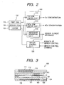
- the gas concentration measuring apparatus also includes an electronic control unit (ECU) 20, a sensor control circuit 510, and a heater control circuit 520.
- ECU electronice control unit
- the ECU 20 receives an output of the gas concentration sensor 100 and engine operating data on engine speed, inlet air pressure, water temperature, and throttle opening measured by known sensors (not shown) to control the quantity of fuel supplied by the fuel injector 12 and the ignition timing through an ignition system 15.
- the ECU 20 also receives an O 2 concentration signal which is proportional to an air-fuel ratio of a mixture supplied to the engine 10 and which will also be referred to as an A/F signal and a NOx concentration signal outputted from the sensor control circuit 510.
- the sensor control circuit 510 picks up the pump cell current and the sensor cell current from the gas concentration sensor 100 to calculate the concentrations of O 2 and NOx in the exhaust gasses and outputs signals indicative thereof to the ECU 20.
- the sensor control circuit 510 also picks up data on a sensor element temperature determined as a function of a sensor element resistance which indicates the active state of the gas concentration sensor 100 and outputs a signal indicative thereof to the ECU 20.
- the heater control circuit 520 receives the sensor element temperature data from the ECU 20 to control the power supply to the heater 103 for maintaining the gas concentration sensor 100 activated.
- the sensor control circuit 510 and the heater control circuit 520 are built in a connector 300 connecting between the ECU 20 and the gas concentration sensor 100. Specifically, in a typical prior art structure, the sensor control circuit 510 and the heater control circuit 520 are disposed in the ECU 20, but in this embodiment, they are integrated near the gas concentration sensor 100. This is because there are three main reasons below:
- the oxygen concentration determining circuit 511, the NOx concentration determining circuit 512, the impedance measuring circuit 513, and the heater control circuit 520 may be formed on a single bare chip mounted on a ceramic substrate or a ceramic multi-layered board, thereby also resulting in a compact structure and greatly improved heat and vibration resistances.
- the sensor control circuit 510 connects electrically with the gas concentration sensor 100 through conductors 401.
- the heater control circuit 520 connects electrically with the heater 103 through a conductor 402.
- the gas concentration sensor 100 has a cover 160 and a sensor element 150 disposed within the cover 160.
- the sensor element 150 consists of the pump cell 110, the sensor cell 120, and the heater 103, as shown in Fig. 3.
- the cover 160 has formed therein a plurality of pin holes through which the exhaust gasses flow into the cover 160.
- the connector 300 includes a casing 310 and a plug 320.
- the casing 310 has disposed therein the sensor control circuit 510 and the heater control circuit 520, thereby minimizing addition of external electric noises thereto.
- the sensor control circuit 510 includes, as clearly shown in Fig. 2, an oxygen concentration determining circuit 511, a NOx concentration determining circuit 512, and a sensor element impedance measuring circuit 513.
- the oxygen concentration determining circuit 511 is connected to the pump cell 110 of the gas concentration sensor 100 to measure an electric current or the pump cell current flowing through the pump cell 110 as a function of the concentration of O 2 and converts it into a voltage signal which is, in turn, outputted to the ECU 20.
- the oxygen concentration determining circuit 511 is also responsive to the pump cell current to adjust the voltage applied to the pump cell 110.
- the NOx concentration determining circuit 512 is connected to the sensor cell 120 to measure an electric current or the sensor cell current flowing through the sensor cell 120 as a function of the concentration of NOx and converts it into a voltage signal which is, in turn, outputted to the ECU 20.
- the NOx concentration determining circuit 512 is also responsive to the sensor cell current to adjust the voltage applied to the sensor cell 120.
- the sensor element impedance measuring circuit 513 measures the impedance of the sensor cell 120 or the pump cell 110 in a sweep method and outputs a signal indicative thereof to the heater control circuit 520.
- the heater control circuit 520 is responsive to the signal indicative of the impedance outputted from the sensor cell impedance measuring circuit 513 to control the power supply to the heater 103.
- Japanese Patent Application No. 10-275521 and Japanese Patent First Publication No. 8-278279 teach heater control systems, disclosure of which is incorporated herein by reference.
- the sensor control circuit 510 includes, as clearly shown in Fig. 7, a microcomputer 200 consisting of a CPU, A/D converters, and D/A converters. To the A/D converters A/D0 to A/D3, voltages appearing at terminals Vc, Ve, Vd, and Vb are inputted. From the D/A converters D/A1 and D/A0, a pump cell control voltage Vb and the sensor cell control voltage Vc are outputted. From the D/A converters D/A2 and D/A3, an O 2 concentration output and a NOx concentration output are provided.
- the pump cell control voltage Vb is inputted to an non-inverting input of the amplifier 211.
- An output of the amplifier 211 is connected to one end of the resistor 212 used in measuring the pump cell current Ip flowing through the pump cell 110 as a function of the concentration of O 2 .
- the other end of the resistor 212 is connected to the first pump cell electrode 111 of the gas concentration sensor 100 and an inverting input of the amplifier 211, thereby controlling the voltage appearing at the first pump cell electrode 111 so as to be kept at the same potential as the pump cell control voltage Vb.
- the resistor 212 also connects at both ends to the A/D converters A/D2 and A/D3.
- the microcomputer 200, the amplifier 211, and the resistor 212 constitute the oxygen concentration determining circuit 511.
- the sensor cell control voltage Vc outputted from the D/A converter D/A0 is inputted to an non-inverting input of the amplifier 221 through a low-pass filter 230.
- the low-pass filter 230 may be a primary filter consisting of a capacitor.
- An output of the amplifier 221 is connected to one end of the resistor 222 used in measuring the sensor cell current Is flowing through the sensor cell 120 as a function of the concentration of NOx.
- the other end of the resistor 222 is connected to the second sensor cell electrode 122 of the gas concentration sensor 100 and an inverting input of the amplifier 221, thereby controlling the voltage appearing at the second sensor cell electrode 122 to be kept at the same potential as the sensor cell control voltage Vc .
- the resistor 222 connects at both ends thereof to the A/D converters A/D0 and A/D1 of the microcomputer 200.
- the microcomputer 200, the amplifier 221, and the resistor 222 constitute the NOx concentration determining circuit 512.
- the microcomputer 200 measures an a.c. impedance of the sensor cell 120 using the sweep method. Specifically, the measurement of the AC impedance is achieved by changing the sensor cell control voltage Vc outputted from the D/A converter D/A0 instantaneously to apply an ac voltage to the sensor cell 120 which is blurred in the form of a sine wave through the low-pass filter 230.
- the frequency of the ac voltage is preferably higher than 10KHz.
- the time constant of the low-pass filter 230 is in the order of 5 ⁇ s.
- the microcomputer 200 monitors changes in voltage Ve and Vc appearing at the terminals Ve and Vc through the A/D converters A/D1 and A/D0 to determine a change in voltage difference across the resistor 222 and a change in sensor current and calculates the a.c. impedance of the sensor cell 120 based on the changes in voltage difference and sensor current.
- the microcomputer 200 outputs a signal indicative of the a.c. impedance of the sensor call 120 to the heater control circuit 520 through a D/A converter or a serial communication port.
- the microcomputer 200, the amplifier 221, and the resistor 222 constitute the sensor element impedance measuring circuit 513.
- the microcomputer 200 outputs a control signal having a given duty factor through an I/O port to operate a MOSFET driver 521.
- the MOSFET driver 521 activates the MOSFET 522 to regulate the power supplied from a power source 523 such as a battery to the heater 103 under the PWM control.
- the microcomputer 200, the MOSFET driver 521, and the MOSFET 522 constitute the heater control circuit 520.
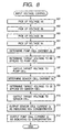
- Fig. 8 shows a flowchart of a program or a sequence of logical steps performed by the CPU of the microcomputer 200 in the course of execution of a main program (not shown), for example, an air-fuel ratio control program to control the pump cell control voltage Vb and the sensor cell control voltage Vc inputted to the pump cell 110 and the sensor cell 120.
- a main program for example, an air-fuel ratio control program to control the pump cell control voltage Vb and the sensor cell control voltage Vc inputted to the pump cell 110 and the sensor cell 120.
- step 101 the CPU picks up the voltage Vd which is developed at the terminal Vd (i.e., one end of the resistor 212) and converted into a digital signal through the A/D converter A/D2.
- steps 102, 103, and 104 the CPU picks up the voltages Vb, Ve, and Vc which are developed at the terminals Vc, Ve, and Vc and converted into digital signals through the A/D converters A/D3, A/D1, and A/D0, respectively.
- step 106 a target input voltage to be applied to the pump cell 110 is determined which corresponds to the pump cell current Ip on the voltage line LX1 shown in Fig. 5.
- step 107 the target input voltage determined in step 106 is outputted as the pump cell control voltage Vb through the D/A converter D/A1.
- the routine proceeds to step 109 wherein a target input voltage to be applied to the sensor cell 120 is determined which corresponds to the sensor cell current Is on the voltage line LX2 shown in Fig. 6.
- the routine proceeds to step 110 wherein the target input voltage determined in step 109 is outputted as the sensor cell control voltage Vc through the D/A converter D/A0.
- the routine proceeds to step 111 wherein the sensor cell current Is is outputted as indicating the concentration of NOx to the ECU 20 through, for example, a serial communication port.
- the routine proceeds to step 112 wherein the pump cell current Ip is outputted as indicating the concentration of O 2 to the ECU 20 through, for example, a serial communication port.
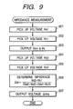
- Fig. 9 shows a subprogram for determining the sensor element impedance which is executed by the CPU of the microcomputer 200 selectively at regular intervals of 128ms in a start-up mode of engine operation and at regular intervals of 256ms after the engine is warmed up.
- the routine proceeds to steps 201 and 202 wherein the voltages Ve and Vc developed across the resistor 222 are picked up through the A/D converters A/D1 and A/D0, which will be referred to as Ve1 and Ve2 below.
- step 203 the sum of a sensor cell control voltage Vs now applied to the sensor cell 120 and an additional a.c. voltage ⁇ Vs is outputted from the D/A converter D/A0, thereby causing, as shown in Fig. 10, the voltages Vc and Ve developed across the resistor 222 to change in the form of a sine wave according to the time constant of the low-pass filter 230.
- the routine proceeds to steps 204 and 205 wherein the voltages appearing at the terminals Ve and Vc , which will be referred to as Ve2 and Vc2 below, are picked up 20 ⁇ s after the voltage applied to the resistor 222 is changed in step 203.
- step 207 a negative voltage ⁇ Vs2 is, as shown in Fig. 10, outputted from the D/A converter D/A0 temporarily to return the voltage applied to the sensor cell 120 to the voltage Vs .
- an electric current flowing through the gas concentration sensor 100 as a function of the concentration of each of O 2 and NOx is, as described above, extremely weak, so that it apt to interfere with electrical noises produced from peripheral devices.
- the concentration of NOx is within 0 to 2000ppm
- the current outputted from the gas concentration sensor 100 as a function of the concentration of NOx is, as shown in Fig. 6, as little as 5 to 10 ⁇ A, thus resulting in a failure in measuring the concentration of NOx accurately.
- this embodiment specifies the length of the conductors 401 connecting between the gas concentration sensor 100 and the sensor control circuit 510 and the length of the conductor 402 connecting between the heater 103 and the heater control circuit 520 using a suitable relation, as shown in Fig. 12, between the length of a wire extending from each of a cup-shaped A/F sensor, a laminated A/F sensor, and a NOx sensor (i.e., the gas concentration sensor 100) and the level of an output signal thereof.
- a gas concentration sensor such as the one in this embodiment designed to measure the concentration of NOx is required to shorten the length of wire extending therefrom as compared with the cup-shaped or laminated A/F sensors. Minimizing the interference of an output of the gas concentration sensor 100 with electric noises, thus, requires decreasing the length of the conductors 401 and 402. Further, in a case where the gas concentration sensor 100 is mounted in an automotive vehicle, various electric noises are added to an output of the gas concentration sensor 100. Therefore, the lower the level of the output of the gas concentration sensor 100, the better the decrease in distance between the gas concentration sensor 100 and the connector 300 to minimize the electric noises.
- the sensor element of the gas concentration sensor 100 contains ceramic, so that it has characteristics of a flow of d.c. current, and a flow of a.c. current, and an output indicating the concentration of gas that undergo an inevitable unit-to-unit deviation in mass production, thus resulting in a decrease in production yield.
- a small variation in production condition will cause the characteristics and the impedance of sensors to change.
- Some of the sensors whose characteristics are below standards are usually discarded, thus resulting in a decrease in production yield.
- an actual output of the gas concentration sensor 100 is shifted from a correct one, as indicated by a broken line.
- the resistance value of the heater 103 is set small in order to speed up the activity of the gas concentration sensor 100. At the start of the control of the heater 103, it is usually difficult to measure the impedance of the gas concentration sensor 100 sensor accurately.
- the ECU 20 may, thus, monitor the power supplied to the heater 103 from the heater control circuit 520 (i.e., the heater voltage and current) and provide a power supply control signal to the heater control circuit 520.
- the resistance value of the conductor 402 (including resistance values of the heater 103 and the heater control circuit 520) differs among vehicles, it will cause the controllability of the heater 103 to vary, resulting in, for example, a decrease in heat produced by the heater 103 and an error in measuring the power supplied to the heater 103, which may lead to a delay in activating the gas concentration sensor 100 and overheating thereof.
- the sensor control circuit 510 of this embodiment is, as described later in detail, designed to adjust or correct the characteristics of the gas concentration sensor 100, and the heater control circuit 520 is designed to compensate for the error in measuring the power supplied to the heater 103 depending upon the resistance of the conductor 402.
- the correction of the characteristics of the gas concentration sensor 100 and the compensation of the error in measuring the power supplied to the heater 103 are accomplished with gain adjustment and offset adjustment in the sensor control circuit 510 and the heater control circuit 520 in manufacturing processes. Such adjustments may be achieved with
- correction circuit 531, 532, and 533 may be connected to outputs of the oxygen concentration determining circuit 512, the NOx concentration determining circuit 512, and the impedance measuring circuit 513, respectively.
- Each of the correction circuits 531, 532, and 533 is made of a resistor such as a shunt which is trimmed to adjust a resistance value thereof so as to bring an actual output of a corresponding one of the oxygen concentration determining circuit 511, the NOx concentration determining circuit 512, and the impedance measuring circuit 533 into agreement with a correct or desired one.
- a gain/offset adjustment map may be pre-stored in the microcomputer 200 which is used in calculating and adjusting a gain or an offset of the amplifiers 211 and 221 to bring an actual output of each of the oxygen concentration determining circuit 512, the NOx concentration determining circuit 512, and the impedance measuring circuit 533 into agreement with a correct or desired one.
- parameters used in calculating and adjusting the gain and offset may be inputted directly to the microcomputer 200 through an A/D converter.
- a correction circuit 534 similar to one of the correction circuits 531, 532, and 533, may be built in the heater control circuit 520.
- the microcomputer 200 may calculate a gain or an offset of the heater control circuit 520 in the same manner as described above to bring the output signal into agreement with a correct one.
- the NOx concentration determining circuit 512 which receives a weak electrical signal (i.e., the sensor cell current) from the gas concentration sensor 100 may be disposed within the connector 300 to shorten the distance to the gas concentration sensor 100 or the length of a conductor connecting between the NOx concentration determining circuit 512 and the gas concentration sensor 100 for minimizing addition of electrical noises.
- any one of the oxygen concentration determining circuit 511, the impedance measuring circuit 513, and the heater control circuit 520 may also be disposed within the connector 300, thereby allowing the length of conductors between the circuits 511, 512, 513, and 520 and the gas concentration sensor 100 to be determined selectively, thus resulting in an increase in freedom of design.
- the first sensor cell electrode 121 and the second pump cell electrode 112 are, as clearly shown in Fig. 7, connected to ground, but may alternatively be connected to a common terminal which is kept at a positive potential. This allows a negative electric current to flow through each of the pump cell 110 and the sensor cell 120.
- a rich gas which usually reduces a flow of the negative current and changes a balance of concentration of O 2 in the porous diffused layer 101 enters the gas concentration sensor 100, it becomes possible to keep the concentration of gas, for example, O 2 in the porous diffused layer 101 at a constant value equivalent to the stoichiometric.
- This enables the rich gas to be measured accurately, thus resulting in an increase in measurable range of the gas concentration sensor 100 and also results in greatly improved response rate of the gas concentration sensor 100 when the gas returns from the rich to lean side.
- the present invention may be used with an air-fuel ratio (A/F) sensor designed to measure the concentration of O 2 contained in exhaust gasses of an internal combustion engine for determining an air-fuel ratio of a mixture supplied to the engine.
- A/F air-fuel ratio
- a cup-shaped A/F sensor in which a solid electrolyte body and a diffused resistance layer are cup-shaped and a laminated A/F sensor made of a lamination of a solid electrolyte plate and a diffused resistance layer are known.
- the air-fuel ratio is 12 to 18, the laminated A/F sensor outputs a current signal of as little as -0.75 to 0.4mA, but the structure of this invention reduces addition of electric noises to an output of the laminated A/F sensor sufficiently.
- the present invention may also be used with three-cell or four-cell gas concentration sensors which are known in the art.
- the present invention may further be used with a gas concentration sensor which is designed to decompose and discharge O 2 contained in gasses to be measured through a pump cell and decompose HC and/or CO contained in the gasses after the decomposition of O 2 through a sensor cell for determining the concentration of O 2 and the concentration of HC and/or CO.
- a gas concentration sensor which is designed to decompose and discharge O 2 contained in gasses to be measured through a pump cell and decompose HC and/or CO contained in the gasses after the decomposition of O 2 through a sensor cell for determining the concentration of O 2 and the concentration of HC and/or CO.
- a gas concentration measuring apparatus which has a gas sensor designed to measure, for example, the concentrations of O 2 and HOx contained in exhaust emissions of an automotive engine is provided.
- the apparatus includes a signal processing circuit which converts a current signal outputted from the gas sensor as a function of the concentration of either of O 2 and HOx into a voltage signal.
- the gas sensor and the signal processing circuit are connected electrically through a conductor.
- the conductor has a length which is determined as a function of a level of the current signal outputted from the gas sensor. The weaker the level of the current signal is, the shorter the length of the conductor. This minimizes addition of electrical noises to the current signal outputted from the gas sensor.
Landscapes
- Chemical & Material Sciences (AREA)
- Life Sciences & Earth Sciences (AREA)
- Health & Medical Sciences (AREA)
- Biochemistry (AREA)
- Chemical Kinetics & Catalysis (AREA)
- Electrochemistry (AREA)
- Physics & Mathematics (AREA)
- Analytical Chemistry (AREA)
- Molecular Biology (AREA)
- General Health & Medical Sciences (AREA)
- General Physics & Mathematics (AREA)
- Immunology (AREA)
- Pathology (AREA)
- Investigating Or Analyzing Materials By The Use Of Electric Means (AREA)
- Combined Controls Of Internal Combustion Engines (AREA)
- Measuring Oxygen Concentration In Cells (AREA)
Applications Claiming Priority (3)
| Application Number | Priority Date | Filing Date | Title |
|---|---|---|---|
| JP34565498A JP4153113B2 (ja) | 1998-12-04 | 1998-12-04 | ガス濃度検出装置 |
| JP34565498 | 1998-12-04 | ||
| EP99124214A EP1006351B1 (fr) | 1998-12-04 | 1999-12-03 | Capteur de gaz avec de courtes connexions à un connecteur, qui contient un circuit de traitement de signaux, pour minimiser le brouillage |
Related Parent Applications (1)
| Application Number | Title | Priority Date | Filing Date |
|---|---|---|---|
| EP99124214A Division EP1006351B1 (fr) | 1998-12-04 | 1999-12-03 | Capteur de gaz avec de courtes connexions à un connecteur, qui contient un circuit de traitement de signaux, pour minimiser le brouillage |
Publications (2)
| Publication Number | Publication Date |
|---|---|
| EP1369685A2 true EP1369685A2 (fr) | 2003-12-10 |
| EP1369685A3 EP1369685A3 (fr) | 2004-02-11 |
Family
ID=18378070
Family Applications (2)
| Application Number | Title | Priority Date | Filing Date |
|---|---|---|---|
| EP99124214A Expired - Lifetime EP1006351B1 (fr) | 1998-12-04 | 1999-12-03 | Capteur de gaz avec de courtes connexions à un connecteur, qui contient un circuit de traitement de signaux, pour minimiser le brouillage |
| EP03018575A Ceased EP1369685A3 (fr) | 1998-12-04 | 1999-12-03 | Capteur de gaz avec de courtes connexions à un connecteur, qui contient un circuit de traitement de signaux, pour minimiser le brouillage |
Family Applications Before (1)
| Application Number | Title | Priority Date | Filing Date |
|---|---|---|---|
| EP99124214A Expired - Lifetime EP1006351B1 (fr) | 1998-12-04 | 1999-12-03 | Capteur de gaz avec de courtes connexions à un connecteur, qui contient un circuit de traitement de signaux, pour minimiser le brouillage |
Country Status (4)
| Country | Link |
|---|---|
| US (2) | US6547955B1 (fr) |
| EP (2) | EP1006351B1 (fr) |
| JP (1) | JP4153113B2 (fr) |
| DE (1) | DE69912077T2 (fr) |
Cited By (1)
| Publication number | Priority date | Publication date | Assignee | Title |
|---|---|---|---|---|
| CN105181752A (zh) * | 2015-09-30 | 2015-12-23 | 浙江大学 | 多层式电化学气体传感监测装置 |
Families Citing this family (35)
| Publication number | Priority date | Publication date | Assignee | Title |
|---|---|---|---|---|
| DE10007868B4 (de) * | 2000-02-21 | 2010-02-18 | Robert Bosch Gmbh | Elektronische Steuerschaltung |
| DE10051089C2 (de) * | 2000-10-14 | 2002-09-05 | Conducta Endress & Hauser | Amperometrisches Mess- oder Nachweisverfahren und Vorrichtung zu seiner Durchführung |
| US6831471B2 (en) * | 2002-11-14 | 2004-12-14 | Delphi Technologies, Inc. | Configurable interface circuit for exhaust gas oxygen sensors |
| JP3922239B2 (ja) | 2002-12-26 | 2007-05-30 | 株式会社デンソー | ガス濃度検出装置 |
| JP3763298B2 (ja) * | 2003-01-09 | 2006-04-05 | トヨタ自動車株式会社 | ガス濃度検出装置の故障診断装置 |
| JP4124119B2 (ja) | 2003-01-30 | 2008-07-23 | 株式会社デンソー | ガス濃度検出装置 |
| JP2004286685A (ja) * | 2003-03-24 | 2004-10-14 | Denso Corp | ガス濃度検出装置 |
| US20080017510A1 (en) * | 2004-05-26 | 2008-01-24 | Nair Balakrishnan G | NOx Gas Sensor Method and Device |
| US7114325B2 (en) * | 2004-07-23 | 2006-10-03 | Ford Global Technologies, Llc | Control system with a sensor |
| DE102005006501A1 (de) * | 2005-02-14 | 2006-08-24 | Robert Bosch Gmbh | Gasmessfühler |
| US7644576B2 (en) * | 2005-04-25 | 2010-01-12 | Ngk Spark Plug Co., Ltd. | Sensor control device |
| US7611612B2 (en) * | 2005-07-14 | 2009-11-03 | Ceramatec, Inc. | Multilayer ceramic NOx gas sensor device |
| JP4708999B2 (ja) * | 2005-12-22 | 2011-06-22 | 日本特殊陶業株式会社 | センサ制御用回路ユニット、および検出装置 |
| JP4739104B2 (ja) * | 2006-04-21 | 2011-08-03 | 日本特殊陶業株式会社 | センサ制御装置 |
| KR100778153B1 (ko) | 2006-11-14 | 2007-11-22 | 주식회사 가스트론 | 수신반까지의 전선의 길이에 적응하여 출력전류를 일정하게조절하는 회로를 가진 가스누설 감지기 |
| JP4270286B2 (ja) * | 2007-02-07 | 2009-05-27 | トヨタ自動車株式会社 | ガスセンサ用の制御装置 |
| EP2115402A2 (fr) * | 2007-02-16 | 2009-11-11 | Ceramatec, Inc. | Capteur de no<sb>x</sb>à sélectivité et sensibilité améliorées |
| EP2093562B1 (fr) * | 2008-02-19 | 2017-08-30 | Denso Corporation | Système dispositif de contrôle du capteur de gaz |
| JP5268068B2 (ja) * | 2008-03-13 | 2013-08-21 | 日本特殊陶業株式会社 | センサ制御装置及びセンサ制御システム |
| US8041992B2 (en) * | 2009-05-11 | 2011-10-18 | Technology Currents Llc | Input compensated and/or overcompensated computing |
| DE102010002458A1 (de) * | 2009-09-11 | 2011-03-24 | Robert Bosch Gmbh | Abgassonde |
| DE102009046749A1 (de) * | 2009-11-17 | 2011-05-19 | Robert Bosch Gmbh | Vorrichtung zum Betrieb eines Partikelsensors |
| JP5307878B2 (ja) | 2010-12-17 | 2013-10-02 | 日本特殊陶業株式会社 | センサ装置 |
| WO2013116386A1 (fr) * | 2012-01-31 | 2013-08-08 | Cummins Emission Solutions, Inc. | Capteurs et systèmes d'interface de capteurs |
| US9164080B2 (en) | 2012-06-11 | 2015-10-20 | Ohio State Innovation Foundation | System and method for sensing NO |
| TWI506274B (zh) * | 2012-09-21 | 2015-11-01 | Univ Nat Taiwan Science Tech | 氣體感測器 |
| DE102013204480A1 (de) * | 2013-03-14 | 2014-09-18 | Robert Bosch Gmbh | Abgassensorvorrichtung |
| JP5907129B2 (ja) | 2013-08-22 | 2016-04-20 | 株式会社デンソー | 電子回路基板内蔵コネクタ、及び、電子回路基板内蔵コネクタの製造方法 |
| JP6147630B2 (ja) * | 2013-09-24 | 2017-06-14 | 日本特殊陶業株式会社 | ガスセンサのヒータ制御装置 |
| JP5895931B2 (ja) * | 2013-12-27 | 2016-03-30 | コベルコ建機株式会社 | 建設機械 |
| JP6265094B2 (ja) * | 2014-09-23 | 2018-01-24 | 株式会社デンソー | 制御装置、および、その製造方法 |
| DE102015112105B4 (de) * | 2015-07-24 | 2020-02-06 | Infineon Technologies Ag | Sensorvorrichtung, Auswertungsvorrichtung und entsprechende Systeme und Verfahren |
| JP6816680B2 (ja) * | 2017-09-07 | 2021-01-20 | トヨタ自動車株式会社 | 排気センサの診断装置 |
| JP6989336B2 (ja) * | 2017-10-06 | 2022-01-05 | 日本特殊陶業株式会社 | センサ制御装置およびセンサユニット |
| WO2020189380A1 (fr) * | 2019-03-15 | 2020-09-24 | 日本特殊陶業株式会社 | Dispositif de commande de capteur de gaz, système de commande de capteur de gaz, et système de capteur de gaz |
Citations (9)
| Publication number | Priority date | Publication date | Assignee | Title |
|---|---|---|---|---|
| US3851929A (en) | 1972-03-09 | 1974-12-03 | Citroen Sa | Braking mechanism tending to eliminate locking |
| EP0120423A1 (fr) | 1983-03-18 | 1984-10-03 | Hitachi, Ltd. | Détecteur du rapport air-carburant |
| US5323635A (en) | 1992-06-01 | 1994-06-28 | Hitachi, Ltd. | Air fuel ratio detecting arrangement and method therefor for an internal combustion engine |
| EP0841562A2 (fr) * | 1996-11-08 | 1998-05-13 | Ngk Spark Plug Co., Ltd | Méthode et appareil pour mesurer la concentration d'oxygène et d'oxyde d'azote |
| US5812880A (en) | 1995-03-10 | 1998-09-22 | Nippondenso Co., Ltd. | Multi-CPU system's data I/O processor with communication arbitrator performing access operations on I/O connected to a first CPU bus on behalf of a second CPU |
| EP0878709A2 (fr) * | 1997-03-21 | 1998-11-18 | NGK Spark Plug Co. Ltd. | Procédé et appareil de mesure de la concentration d'oxydes d'azote |
| DE19822801A1 (de) * | 1997-05-21 | 1998-11-26 | Denso Corp | Vorrichtung und Verfahren zur Gaskonzentrationserfassung sowie Herstellungsverfahren für die Vorrichtung |
| EP0884587A1 (fr) * | 1997-06-13 | 1998-12-16 | NGK Spark Plug Co. Ltd. | Appareil pour déterminer la concentration de NOx |
| WO1999042717A1 (fr) * | 1998-02-20 | 1999-08-26 | Siemens Aktiengesellschaft | Systeme de commande pour moteur a combustion interne comportant un capteur et une interface pour la numerisation des valeurs de mesure |
Family Cites Families (19)
| Publication number | Priority date | Publication date | Assignee | Title |
|---|---|---|---|---|
| US4457808A (en) * | 1983-05-16 | 1984-07-03 | General Signal Corporation | Method and means for recalibrating electrochemical cells in situ |
| JPH0727391Y2 (ja) * | 1986-02-04 | 1995-06-21 | 本田技研工業株式会社 | 内燃エンジンの空燃比制御装置 |
| JPS6321549A (ja) * | 1986-07-15 | 1988-01-29 | Ngk Insulators Ltd | 限界電流測定回路 |
| US4822456A (en) * | 1987-06-05 | 1989-04-18 | Bryan Avron I | Ion measuring apparatus and monitoring system |
| US4963246A (en) * | 1987-12-14 | 1990-10-16 | Honda Giken Kogyo Kabushiki Kaisha | Oxygen concentration-sensing device |
| JPH0391945A (ja) | 1989-09-04 | 1991-04-17 | Nec Eng Ltd | シャッター付きeprom |
| JP2885336B2 (ja) | 1994-04-21 | 1999-04-19 | 日本碍子株式会社 | 被測定ガス中のNOx濃度の測定方法及び測定装置 |
| US5672811A (en) | 1994-04-21 | 1997-09-30 | Ngk Insulators, Ltd. | Method of measuring a gas component and sensing device for measuring the gas component |
| JP3487009B2 (ja) * | 1994-08-05 | 2004-01-13 | 株式会社デンソー | 酸素センサのヒータ制御装置 |
| US6084418A (en) * | 1996-02-28 | 2000-07-04 | Denso Corporation | Method for accurately detecting sensor element resistance |
| US5993623A (en) * | 1996-09-24 | 1999-11-30 | Rosemount Analytical Inc. | Solid electrolyte gas analyzer with improved circuit and housing configuration |
| JP3796333B2 (ja) | 1996-12-20 | 2006-07-12 | 日本碍子株式会社 | ガスセンサ |
| JPH10271476A (ja) | 1997-03-26 | 1998-10-09 | Nec Home Electron Ltd | テレビ電話会議装置 |
| DE69808749D1 (de) * | 1997-04-24 | 2002-11-21 | Daikin Ind Ltd | Kammförmiges Sensorelement mit Elektroden auf den Zähnen und Kantenanschlüssen auf der gegenüberliegenden Seite |
| JP3515372B2 (ja) | 1997-06-20 | 2004-04-05 | 日本特殊陶業株式会社 | 酸化物ガス濃度検出装置及びそれに用いられる記憶媒体 |
| JP3372195B2 (ja) | 1997-08-14 | 2003-01-27 | 日本特殊陶業株式会社 | NOxガス濃度検出器及び検出器に用いる電極の製造方法 |
| RU2135991C1 (ru) | 1998-02-10 | 1999-08-27 | Журавков Игорь Викторович | Способ осуществления электрического пробоя газового диэлектрика в резконеоднородном поле |
| EP1890139B1 (fr) * | 1998-02-20 | 2012-12-12 | NGK Spark Plug Co., Ltd. | Système de capteur de NOx avec unité de circuit de commande |
| DE19836127A1 (de) | 1998-08-10 | 2000-02-24 | Siemens Ag | Verfahren und Vorrichtung zum Kalibrieren eines Sondensystems, bestehend aus einer Abgassonde und einer Regelschaltung für ein Kraftfahrzeug |
-
1998
- 1998-12-04 JP JP34565498A patent/JP4153113B2/ja not_active Expired - Lifetime
-
1999
- 1999-12-03 US US09/453,518 patent/US6547955B1/en not_active Expired - Fee Related
- 1999-12-03 DE DE69912077T patent/DE69912077T2/de not_active Expired - Lifetime
- 1999-12-03 EP EP99124214A patent/EP1006351B1/fr not_active Expired - Lifetime
- 1999-12-03 EP EP03018575A patent/EP1369685A3/fr not_active Ceased
-
2003
- 2003-02-26 US US10/373,289 patent/US6849174B2/en not_active Expired - Fee Related
Patent Citations (9)
| Publication number | Priority date | Publication date | Assignee | Title |
|---|---|---|---|---|
| US3851929A (en) | 1972-03-09 | 1974-12-03 | Citroen Sa | Braking mechanism tending to eliminate locking |
| EP0120423A1 (fr) | 1983-03-18 | 1984-10-03 | Hitachi, Ltd. | Détecteur du rapport air-carburant |
| US5323635A (en) | 1992-06-01 | 1994-06-28 | Hitachi, Ltd. | Air fuel ratio detecting arrangement and method therefor for an internal combustion engine |
| US5812880A (en) | 1995-03-10 | 1998-09-22 | Nippondenso Co., Ltd. | Multi-CPU system's data I/O processor with communication arbitrator performing access operations on I/O connected to a first CPU bus on behalf of a second CPU |
| EP0841562A2 (fr) * | 1996-11-08 | 1998-05-13 | Ngk Spark Plug Co., Ltd | Méthode et appareil pour mesurer la concentration d'oxygène et d'oxyde d'azote |
| EP0878709A2 (fr) * | 1997-03-21 | 1998-11-18 | NGK Spark Plug Co. Ltd. | Procédé et appareil de mesure de la concentration d'oxydes d'azote |
| DE19822801A1 (de) * | 1997-05-21 | 1998-11-26 | Denso Corp | Vorrichtung und Verfahren zur Gaskonzentrationserfassung sowie Herstellungsverfahren für die Vorrichtung |
| EP0884587A1 (fr) * | 1997-06-13 | 1998-12-16 | NGK Spark Plug Co. Ltd. | Appareil pour déterminer la concentration de NOx |
| WO1999042717A1 (fr) * | 1998-02-20 | 1999-08-26 | Siemens Aktiengesellschaft | Systeme de commande pour moteur a combustion interne comportant un capteur et une interface pour la numerisation des valeurs de mesure |
Non-Patent Citations (3)
| Title |
|---|
| "INTEGRATED SMART SENSORS DESIGN AND CALIBRATION", 31 December 1997, KLUWER ACADEMIC PUBLISHERS, Netherlands, ISBN: 978-0-79-238004-7, article GERT VAN DER HORN ET AL: "INTEGRATED SMART SENSORS DESIGN AND CALIBRATION", XP055076058 * |
| INAGAKI H ET AL: "NOX METER UTILIZING ZRO2 PUMPING CELL", ALUMINUM APPLICATIONS FOR AUTOMOTIVE DESIGN. DETROIT, 1995; [SAE INTERNATIONAL CONGRESS AND EXPOSITION], WARRENDALE, SAE, US, vol. 1312, 23 February 1998 (1998-02-23), pages 29 - 35, XP009052034, ISBN: 978-1-56091-647-5 * |
| KATO ET AL: "Long Term Stable NOx Sensor with Integrated In-Connector Control Electronics", SAE TECHNICAL PAPER SERIES, SOCIETY OF AUTOMOTIVE ENGINEERS, WARRENDALE, PA, US, vol. 1418/1999-01-0202, 1 March 1999 (1999-03-01), pages 1 - 8, XP009171847, ISSN: 0148-7191, DOI: 10.4271/1999-01-0202 * |
Cited By (1)
| Publication number | Priority date | Publication date | Assignee | Title |
|---|---|---|---|---|
| CN105181752A (zh) * | 2015-09-30 | 2015-12-23 | 浙江大学 | 多层式电化学气体传感监测装置 |
Also Published As
| Publication number | Publication date |
|---|---|
| DE69912077T2 (de) | 2004-08-26 |
| US20030155238A1 (en) | 2003-08-21 |
| JP2000171435A (ja) | 2000-06-23 |
| DE69912077D1 (de) | 2003-11-20 |
| JP4153113B2 (ja) | 2008-09-17 |
| US6547955B1 (en) | 2003-04-15 |
| EP1006351B1 (fr) | 2003-10-15 |
| EP1006351A1 (fr) | 2000-06-07 |
| US6849174B2 (en) | 2005-02-01 |
| EP1369685A3 (fr) | 2004-02-11 |
Similar Documents
| Publication | Publication Date | Title |
|---|---|---|
| EP1006351B1 (fr) | Capteur de gaz avec de courtes connexions à un connecteur, qui contient un circuit de traitement de signaux, pour minimiser le brouillage | |
| US8052863B2 (en) | Gas sensor control apparatus designed to ensure accuracy of measurement in gas sensor | |
| US6295862B1 (en) | Gas concentration measuring apparatus compensating for error component of output signal | |
| EP0878709B1 (fr) | Procédé et appareil de mesure de la concentration d'oxydes d'azote | |
| US6347277B2 (en) | Method and device for calibrating a probe system | |
| EP1764613B1 (fr) | Appareil pour mesurer la concentration de gaz | |
| US5236569A (en) | Air/fuel ratio sensor having resistor for limiting leak current from pumping cell to sensing cell | |
| US7875165B2 (en) | Method of correcting output of NOx sensor | |
| US9518954B2 (en) | Gas sensor control device | |
| US6258232B1 (en) | Gas component concentration measuring apparatus | |
| EP1860431B1 (fr) | Appareil de mesure de concentration de gaz avec plusieurs gammes d'amplification | |
| JP2012093376A (ja) | センサ制御装置 | |
| US20030201193A1 (en) | Method of adjusting output of gas sensor | |
| US6348140B1 (en) | Gas sensor with a high combined resistance to lead wire resistance ratio | |
| JP3310273B2 (ja) | ガス濃度検出装置 | |
| US8474302B2 (en) | Sensor control unit and gas detection apparatus | |
| JPH11344466A (ja) | ガス濃度センサのヒータ制御装置 | |
| KR100230537B1 (ko) | 가스 혼합물 내의 성분 농도의 측정 장치 | |
| US20070215470A1 (en) | Gas concentration measuring apparatus designed to enhance response of sensor | |
| US6524467B2 (en) | Method for adjusting output characteristics of a gas sensing element based on application of electric power to this sensing element | |
| US6636051B2 (en) | Wiring harness plug, especially as planar two-cell limiting current probe having an injection-molded cover element | |
| JP3267326B2 (ja) | センサ調整装置 | |
| US20050040040A1 (en) | Gas sensor | |
| CN117043592A (zh) | 气体浓度检测装置 | |
| JP2004028925A (ja) | NOx測定装置及びNOxセンサの出力補正方法 |
Legal Events
| Date | Code | Title | Description |
|---|---|---|---|
| PUAI | Public reference made under article 153(3) epc to a published international application that has entered the european phase |
Free format text: ORIGINAL CODE: 0009012 |
|
| AC | Divisional application: reference to earlier application |
Ref document number: 1006351 Country of ref document: EP Kind code of ref document: P |
|
| AK | Designated contracting states |
Kind code of ref document: A2 Designated state(s): DE FR GB |
|
| PUAL | Search report despatched |
Free format text: ORIGINAL CODE: 0009013 |
|
| AK | Designated contracting states |
Kind code of ref document: A3 Designated state(s): DE FR GB |
|
| RIC1 | Information provided on ipc code assigned before grant |
Ipc: 7G 01N 27/417 A |
|
| 17P | Request for examination filed |
Effective date: 20040402 |
|
| AKX | Designation fees paid |
Designated state(s): DE |
|
| TPAC | Observations filed by third parties |
Free format text: ORIGINAL CODE: EPIDOSNTIPA |
|
| 17Q | First examination report despatched |
Effective date: 20050817 |
|
| TPAC | Observations filed by third parties |
Free format text: ORIGINAL CODE: EPIDOSNTIPA |
|
| TPAC | Observations filed by third parties |
Free format text: ORIGINAL CODE: EPIDOSNTIPA |
|
| STAA | Information on the status of an ep patent application or granted ep patent |
Free format text: STATUS: THE APPLICATION HAS BEEN REFUSED |
|
| 18R | Application refused |
Effective date: 20131125 |