EP1366294B1 - Rotary positive displacement machine - Google Patents
Rotary positive displacement machine Download PDFInfo
- Publication number
- EP1366294B1 EP1366294B1 EP01947673A EP01947673A EP1366294B1 EP 1366294 B1 EP1366294 B1 EP 1366294B1 EP 01947673 A EP01947673 A EP 01947673A EP 01947673 A EP01947673 A EP 01947673A EP 1366294 B1 EP1366294 B1 EP 1366294B1
- Authority
- EP
- European Patent Office
- Prior art keywords
- rotor
- positive displacement
- sealing member
- stator
- displacement machine
- Prior art date
- Legal status (The legal status is an assumption and is not a legal conclusion. Google has not performed a legal analysis and makes no representation as to the accuracy of the status listed.)
- Expired - Lifetime
Links
- 238000006073 displacement reaction Methods 0.000 title claims description 15
- 238000007789 sealing Methods 0.000 claims abstract description 20
- 239000012530 fluid Substances 0.000 claims description 3
- 230000004323 axial length Effects 0.000 abstract 1
- 230000002093 peripheral effect Effects 0.000 description 2
- 230000006835 compression Effects 0.000 description 1
- 238000007906 compression Methods 0.000 description 1
- 239000007789 gas Substances 0.000 description 1
- 238000012986 modification Methods 0.000 description 1
- 230000004048 modification Effects 0.000 description 1
- 239000003507 refrigerant Substances 0.000 description 1
Images
Classifications
-
- F—MECHANICAL ENGINEERING; LIGHTING; HEATING; WEAPONS; BLASTING
- F01—MACHINES OR ENGINES IN GENERAL; ENGINE PLANTS IN GENERAL; STEAM ENGINES
- F01C—ROTARY-PISTON OR OSCILLATING-PISTON MACHINES OR ENGINES
- F01C1/00—Rotary-piston machines or engines
- F01C1/30—Rotary-piston machines or engines having the characteristics covered by two or more groups F01C1/02, F01C1/08, F01C1/22, F01C1/24 or having the characteristics covered by one of these groups together with some other type of movement between co-operating members
- F01C1/34—Rotary-piston machines or engines having the characteristics covered by two or more groups F01C1/02, F01C1/08, F01C1/22, F01C1/24 or having the characteristics covered by one of these groups together with some other type of movement between co-operating members having the movement defined in group F01C1/08 or F01C1/22 and relative reciprocation between the co-operating members
- F01C1/356—Rotary-piston machines or engines having the characteristics covered by two or more groups F01C1/02, F01C1/08, F01C1/22, F01C1/24 or having the characteristics covered by one of these groups together with some other type of movement between co-operating members having the movement defined in group F01C1/08 or F01C1/22 and relative reciprocation between the co-operating members with vanes reciprocating with respect to the outer member
- F01C1/3562—Rotary-piston machines or engines having the characteristics covered by two or more groups F01C1/02, F01C1/08, F01C1/22, F01C1/24 or having the characteristics covered by one of these groups together with some other type of movement between co-operating members having the movement defined in group F01C1/08 or F01C1/22 and relative reciprocation between the co-operating members with vanes reciprocating with respect to the outer member the inner and outer member being in contact along one line or continuous surface substantially parallel to the axis of rotation
- F01C1/3564—Rotary-piston machines or engines having the characteristics covered by two or more groups F01C1/02, F01C1/08, F01C1/22, F01C1/24 or having the characteristics covered by one of these groups together with some other type of movement between co-operating members having the movement defined in group F01C1/08 or F01C1/22 and relative reciprocation between the co-operating members with vanes reciprocating with respect to the outer member the inner and outer member being in contact along one line or continuous surface substantially parallel to the axis of rotation the surfaces of the inner and outer member, forming the working space, being surfaces of revolution
-
- F—MECHANICAL ENGINEERING; LIGHTING; HEATING; WEAPONS; BLASTING
- F01—MACHINES OR ENGINES IN GENERAL; ENGINE PLANTS IN GENERAL; STEAM ENGINES
- F01C—ROTARY-PISTON OR OSCILLATING-PISTON MACHINES OR ENGINES
- F01C1/00—Rotary-piston machines or engines
- F01C1/30—Rotary-piston machines or engines having the characteristics covered by two or more groups F01C1/02, F01C1/08, F01C1/22, F01C1/24 or having the characteristics covered by one of these groups together with some other type of movement between co-operating members
- F01C1/40—Rotary-piston machines or engines having the characteristics covered by two or more groups F01C1/02, F01C1/08, F01C1/22, F01C1/24 or having the characteristics covered by one of these groups together with some other type of movement between co-operating members having the movement defined in group F01C1/08 or F01C1/22 and having a hinged member
- F01C1/46—Rotary-piston machines or engines having the characteristics covered by two or more groups F01C1/02, F01C1/08, F01C1/22, F01C1/24 or having the characteristics covered by one of these groups together with some other type of movement between co-operating members having the movement defined in group F01C1/08 or F01C1/22 and having a hinged member with vanes hinged to the outer member
-
- F—MECHANICAL ENGINEERING; LIGHTING; HEATING; WEAPONS; BLASTING
- F04—POSITIVE - DISPLACEMENT MACHINES FOR LIQUIDS; PUMPS FOR LIQUIDS OR ELASTIC FLUIDS
- F04C—ROTARY-PISTON, OR OSCILLATING-PISTON, POSITIVE-DISPLACEMENT MACHINES FOR LIQUIDS; ROTARY-PISTON, OR OSCILLATING-PISTON, POSITIVE-DISPLACEMENT PUMPS
- F04C18/00—Rotary-piston pumps specially adapted for elastic fluids
- F04C18/30—Rotary-piston pumps specially adapted for elastic fluids having the characteristics covered by two or more of groups F04C18/02, F04C18/08, F04C18/22, F04C18/24, F04C18/48, or having the characteristics covered by one of these groups together with some other type of movement between co-operating members
- F04C18/32—Rotary-piston pumps specially adapted for elastic fluids having the characteristics covered by two or more of groups F04C18/02, F04C18/08, F04C18/22, F04C18/24, F04C18/48, or having the characteristics covered by one of these groups together with some other type of movement between co-operating members having both the movement defined in group F04C18/02 and relative reciprocation between the co-operating members
-
- F—MECHANICAL ENGINEERING; LIGHTING; HEATING; WEAPONS; BLASTING
- F04—POSITIVE - DISPLACEMENT MACHINES FOR LIQUIDS; PUMPS FOR LIQUIDS OR ELASTIC FLUIDS
- F04C—ROTARY-PISTON, OR OSCILLATING-PISTON, POSITIVE-DISPLACEMENT MACHINES FOR LIQUIDS; ROTARY-PISTON, OR OSCILLATING-PISTON, POSITIVE-DISPLACEMENT PUMPS
- F04C18/00—Rotary-piston pumps specially adapted for elastic fluids
- F04C18/30—Rotary-piston pumps specially adapted for elastic fluids having the characteristics covered by two or more of groups F04C18/02, F04C18/08, F04C18/22, F04C18/24, F04C18/48, or having the characteristics covered by one of these groups together with some other type of movement between co-operating members
- F04C18/34—Rotary-piston pumps specially adapted for elastic fluids having the characteristics covered by two or more of groups F04C18/02, F04C18/08, F04C18/22, F04C18/24, F04C18/48, or having the characteristics covered by one of these groups together with some other type of movement between co-operating members having the movement defined in group F04C18/08 or F04C18/22 and relative reciprocation between the co-operating members
- F04C18/356—Rotary-piston pumps specially adapted for elastic fluids having the characteristics covered by two or more of groups F04C18/02, F04C18/08, F04C18/22, F04C18/24, F04C18/48, or having the characteristics covered by one of these groups together with some other type of movement between co-operating members having the movement defined in group F04C18/08 or F04C18/22 and relative reciprocation between the co-operating members with vanes reciprocating with respect to the outer member
- F04C18/3562—Rotary-piston pumps specially adapted for elastic fluids having the characteristics covered by two or more of groups F04C18/02, F04C18/08, F04C18/22, F04C18/24, F04C18/48, or having the characteristics covered by one of these groups together with some other type of movement between co-operating members having the movement defined in group F04C18/08 or F04C18/22 and relative reciprocation between the co-operating members with vanes reciprocating with respect to the outer member the inner and outer member being in contact along one line or continuous surfaces substantially parallel to the axis of rotation
- F04C18/3564—Rotary-piston pumps specially adapted for elastic fluids having the characteristics covered by two or more of groups F04C18/02, F04C18/08, F04C18/22, F04C18/24, F04C18/48, or having the characteristics covered by one of these groups together with some other type of movement between co-operating members having the movement defined in group F04C18/08 or F04C18/22 and relative reciprocation between the co-operating members with vanes reciprocating with respect to the outer member the inner and outer member being in contact along one line or continuous surfaces substantially parallel to the axis of rotation the surfaces of the inner and outer member, forming the working space, being surfaces of revolution
Definitions
- the present invention relates to rotary positive displacement machines, particularly, but not solely, for use in heat pumps.
- US-A-3 895 609 discloses a rotary positive displacement machine in accordance with the preamble of claim 1.
- the present invention provides a rotary positive displacement machine as set forth in claim 1.
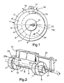
- the rotor 4 has a circular cylindrical external surface 11 with an axis 12 which is eccentric with respect to the axis 8 of the internal surface 3 of the stator 1.
- the axis 8 passes through the rotor 4.
- One generatrix 13 of the external surface 11 (in a plane containing the axes 8, 12) is adjacent to the internal surface 3, with only a small clearance. The diametrically opposite generatrix is spaced from the internal surface 3.
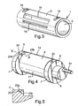
- the stator 1 In the region of each disc 6 and at the same circumferential location, the stator 1 has an inlet port 14 in the form of a slot extending along a circumferential arc. In the region of the operating chamber at a circumferential location spaced from the inlet ports 14, the stator 1 has an outlet port 16 in the form of an axial slot. Between the ports 14 and 16, and close to them, is a sealing member 17 which projects radially through a slot 18 in the stator 1 so as to be movable in the radial direction with respect to the axis 8. The sealing member 17 extends parallel to the axis 8 and has a length substantially equal to that of the rotor 4, with only a small clearance between the ends of the sealing member 17 and the discs 6.
- a link 19 (functioning as a connecting rod) has one end articulated to a pin 21 forming an extension of the rotor 4 on a first articulation axis coincident with the axis 12 and has the other end articulated to a parallel pin 22 mounted on one end of the sealing member 17 and defining a second articulation axis parallel to the first.
- this linkage (19, 21, 22) causes the inner end of the sealing member 17 to closely follow the external surface 11 of the rotor 4 as it rotates about the axis 8.
- a similar linkage may be provided on the opposite end of the machine.
- Each disc 6 has an inlet through-hole 23 with a first end 23a in the periphery 7 and a second end 23b opening into the operating chamber.
- the inlet port 14 only communicates with the operating chamber when the first end 23a overlaps the inlet port 14; otherwise the inlet port 14 is blanked off by the disc 6.
- the above-described machine can be arranged as an expander in a heat pump (not shown) comprising a compressor, a condenser, an expander, and an evaporator, connected in series.
- Return vapour from the condenser is fed to the input ports 14.
- the circumferential length of the slots constituting the ports 14 is chosen to suit the length of time needed for the through-holes 23 to pass a required volume of vapour. Referring to Figure 1, the pressure of the vapour from the through-hole 23, acting on the rotor 4 between the sealing member 17 and the generatrix 13, urges the rotor 4 to turn in the direction of the arrow 24, while the vapour expands as the rotor rotates through nearly 360°. At the same time, previously expanded vapour is driven out through the outlet port 16.
- the machine may be used as a compressor.
- the machine can operate on fluids other than refrigerants, e.g. vapours and gases, in particular air.
- a combined compressor and expander may comprise two stators fixed end-to-end and having a common axis, and two rotors operatively connected to rotate in synchronism.
- one of the discs may be omitted and the end of the stator closed off by a fixed wall delimiting one end of the operating chamber.
- the sealing member may be urged into contact with the rotor by a spring device, instead of using the linkage.
- the rotor could be of any suitable cylindrical shape.
- An outlet port may be opened and closed by a through-hole in one of the discs in a similar way to the inlet port.
Landscapes
- Engineering & Computer Science (AREA)
- Mechanical Engineering (AREA)
- General Engineering & Computer Science (AREA)
- Applications Or Details Of Rotary Compressors (AREA)
- Actuator (AREA)
- Rotary Pumps (AREA)
- Reciprocating Pumps (AREA)
- Centrifugal Separators (AREA)
- Fuel-Injection Apparatus (AREA)
- Hydraulic Motors (AREA)
Applications Claiming Priority (5)
| Application Number | Priority Date | Filing Date | Title |
|---|---|---|---|
| GB0016761A GB0016761D0 (en) | 2000-07-10 | 2000-07-10 | Energy recovery from compressed air or vapour |
| GB0016761 | 2000-07-10 | ||
| GB0101960 | 2001-01-25 | ||
| GB0101960A GB2364552B (en) | 2000-07-10 | 2001-01-25 | Rotary positive displacement machine |
| PCT/GB2001/003089 WO2002004814A2 (en) | 2000-07-10 | 2001-07-09 | Rotary positive displacement machine |
Publications (2)
| Publication Number | Publication Date |
|---|---|
| EP1366294A2 EP1366294A2 (en) | 2003-12-03 |
| EP1366294B1 true EP1366294B1 (en) | 2006-11-22 |
Family
ID=26244621
Family Applications (1)
| Application Number | Title | Priority Date | Filing Date |
|---|---|---|---|
| EP01947673A Expired - Lifetime EP1366294B1 (en) | 2000-07-10 | 2001-07-09 | Rotary positive displacement machine |
Country Status (9)
Families Citing this family (11)
| Publication number | Priority date | Publication date | Assignee | Title |
|---|---|---|---|---|
| GB0222770D0 (en) * | 2002-10-02 | 2002-11-06 | E D Technical Services Ltd | Air cycle heating and cooling |
| GB0413442D0 (en) | 2004-06-16 | 2004-07-21 | Ea Technical Services Ltd | Rolling piston stirling engine |
| EP2072753B1 (en) * | 2006-10-11 | 2018-02-14 | Panasonic Intellectual Property Management Co., Ltd. | Rotary expander |
| US8177536B2 (en) * | 2007-09-26 | 2012-05-15 | Kemp Gregory T | Rotary compressor having gate axially movable with respect to rotor |
| KR101587286B1 (ko) * | 2009-08-10 | 2016-01-21 | 엘지전자 주식회사 | 압축기 |
| CN102022320B (zh) * | 2009-09-23 | 2013-01-09 | 刘邦健 | 连动互轭泵 |
| US9032565B2 (en) | 2009-12-16 | 2015-05-19 | Kohler Co. | Touchless faucet assembly and method of operation |
| HUP1200014A2 (en) * | 2012-01-09 | 2013-09-30 | Magai Istvan Dr | Rotary piston engine |
| CN107989794B (zh) * | 2017-11-23 | 2023-10-03 | 珠海格力节能环保制冷技术研究中心有限公司 | 多级压缩机及具有其的空调器 |
| CA3014193A1 (en) * | 2018-08-15 | 2020-02-15 | Stasinopoulou, Eleni | Vane actuator assembly for a rotary engine |
| CN113359298B (zh) * | 2021-06-18 | 2022-06-03 | 歌尔股份有限公司 | 液压转轴组件及智能眼镜 |
Family Cites Families (13)
| Publication number | Priority date | Publication date | Assignee | Title |
|---|---|---|---|---|
| US154298A (en) * | 1874-08-18 | Improvement in rotary engines | ||
| US1698815A (en) * | 1924-04-29 | 1929-01-15 | Joseph F Jaworowski | Duplex rotary pump |
| GB382567A (en) | 1931-05-11 | 1932-10-27 | Sulzer Ag | Improvements in or relating to rotary piston engines |
| GB381886A (en) | 1931-05-11 | 1932-10-13 | Sulzer Ag | Improvements in or relating to rotary piston engines |
| GB390443A (en) | 1931-10-19 | 1933-04-06 | Eugen Ketterer | Improvements in and relating to tightening means for the compression and suction chambers of rotary piston engines |
| US2425244A (en) * | 1943-08-12 | 1947-08-05 | Jeffries Hugh | Sliding abutment unit for rotary displacement pumps or motors |
| US3895609A (en) * | 1972-08-14 | 1975-07-22 | John M Armstrong | Rotary internal combustion engine |
| US4023540A (en) * | 1976-04-15 | 1977-05-17 | Hans Zollenkopf | Rotary engine |
| DE4320423A1 (de) * | 1993-06-21 | 1994-12-22 | Opel Adam Ag | Rollkolbenmaschine |
| US5713732A (en) * | 1995-03-31 | 1998-02-03 | Riney; Ross W. | Rotary compressor |
| WO1999032985A1 (en) * | 1997-12-22 | 1999-07-01 | Accepted Marketing, Inc. | E-mail filter and method thereof |
| US6563918B1 (en) * | 1998-02-20 | 2003-05-13 | Sprint Communications Company, LP | Telecommunications system architecture for connecting a call |
| US6587441B1 (en) * | 1999-01-22 | 2003-07-01 | Technology Alternatives, Inc. | Method and apparatus for transportation of data over a managed wireless network using unique communication protocol |
-
2001
- 2001-07-09 AT AT01947673T patent/ATE346238T1/de not_active IP Right Cessation
- 2001-07-09 MX MXPA03000345A patent/MXPA03000345A/es active IP Right Grant
- 2001-07-09 JP JP2002509652A patent/JP2004509258A/ja active Pending
- 2001-07-09 AU AU2001269320A patent/AU2001269320A1/en not_active Abandoned
- 2001-07-09 DE DE60124775T patent/DE60124775T2/de not_active Expired - Fee Related
- 2001-07-09 CN CNB018126499A patent/CN1193162C/zh not_active Expired - Fee Related
- 2001-07-09 EP EP01947673A patent/EP1366294B1/en not_active Expired - Lifetime
- 2001-07-09 WO PCT/GB2001/003089 patent/WO2002004814A2/en active IP Right Grant
- 2001-07-09 US US10/332,382 patent/US6729864B2/en not_active Expired - Fee Related
Also Published As
| Publication number | Publication date |
|---|---|
| DE60124775T2 (de) | 2007-09-13 |
| EP1366294A2 (en) | 2003-12-03 |
| JP2004509258A (ja) | 2004-03-25 |
| WO2002004814A2 (en) | 2002-01-17 |
| MXPA03000345A (es) | 2004-12-13 |
| AU2001269320A1 (en) | 2002-01-21 |
| US20030156962A1 (en) | 2003-08-21 |
| DE60124775D1 (de) | 2007-01-04 |
| WO2002004814A3 (en) | 2003-10-02 |
| CN1193162C (zh) | 2005-03-16 |
| ATE346238T1 (de) | 2006-12-15 |
| US6729864B2 (en) | 2004-05-04 |
| CN1469968A (zh) | 2004-01-21 |
Similar Documents
| Publication | Publication Date | Title |
|---|---|---|
| US5609478A (en) | Radial compliance mechanism for corotating scroll apparatus | |
| JP5433831B2 (ja) | スクロール流体機械 | |
| EP1366294B1 (en) | Rotary positive displacement machine | |
| US6093005A (en) | Scroll-type fluid displacement machine | |
| US5616019A (en) | Rolling piston type expansion machine | |
| JP2011012595A (ja) | 回転機械 | |
| AU654598B2 (en) | A method for dynamically balancing nested coupling mechanisms for scroll machines | |
| US5015161A (en) | Multiple stage orbiting ring rotary compressor | |
| US6352418B1 (en) | Displacement type fluid machine | |
| JP4882643B2 (ja) | スクロール型膨張機 | |
| GB2364552A (en) | Rotary positive displacement machine | |
| US5855474A (en) | Multiple purpose two stage rotating vane device | |
| US20210003131A1 (en) | Scroll compressor | |
| JP5613912B2 (ja) | スクロール流体機械 | |
| US2732126A (en) | Refrigerating apparatus | |
| JPH04272401A (ja) | 修正先端封止溝を有するスクロール装置 | |
| KR100575709B1 (ko) | 스크롤 압축기 | |
| EP0711919B1 (en) | Reverse drive oil pump | |
| US6010322A (en) | Rotational power generating device | |
| JPH03145592A (ja) | コンプレッサー | |
| US4191515A (en) | Sealing system for a rotary machine | |
| JPH10266945A (ja) | 流体移送装置 | |
| JP7122112B2 (ja) | スクロール流体機械及びランキンサイクル | |
| JPH04311601A (ja) | スクロール型流体機械 | |
| CA1270798A (en) | Variable capacity scroll type fluid compressor |
Legal Events
| Date | Code | Title | Description |
|---|---|---|---|
| PUAI | Public reference made under article 153(3) epc to a published international application that has entered the european phase |
Free format text: ORIGINAL CODE: 0009012 |
|
| 17P | Request for examination filed |
Effective date: 20030210 |
|
| AK | Designated contracting states |
Kind code of ref document: A2 Designated state(s): AT BE CH CY DE DK ES FI FR GB GR IE IT LI LU MC NL PT SE TR |
|
| GRAP | Despatch of communication of intention to grant a patent |
Free format text: ORIGINAL CODE: EPIDOSNIGR1 |
|
| GRAS | Grant fee paid |
Free format text: ORIGINAL CODE: EPIDOSNIGR3 |
|
| GRAA | (expected) grant |
Free format text: ORIGINAL CODE: 0009210 |
|
| AK | Designated contracting states |
Kind code of ref document: B1 Designated state(s): AT BE CH CY DE DK ES FI FR GB GR IE IT LI LU MC NL PT SE TR |
|
| PG25 | Lapsed in a contracting state [announced via postgrant information from national office to epo] |
Ref country code: NL Free format text: LAPSE BECAUSE OF FAILURE TO SUBMIT A TRANSLATION OF THE DESCRIPTION OR TO PAY THE FEE WITHIN THE PRESCRIBED TIME-LIMIT Effective date: 20061122 Ref country code: FI Free format text: LAPSE BECAUSE OF FAILURE TO SUBMIT A TRANSLATION OF THE DESCRIPTION OR TO PAY THE FEE WITHIN THE PRESCRIBED TIME-LIMIT Effective date: 20061122 Ref country code: LI Free format text: LAPSE BECAUSE OF FAILURE TO SUBMIT A TRANSLATION OF THE DESCRIPTION OR TO PAY THE FEE WITHIN THE PRESCRIBED TIME-LIMIT Effective date: 20061122 Ref country code: AT Free format text: LAPSE BECAUSE OF FAILURE TO SUBMIT A TRANSLATION OF THE DESCRIPTION OR TO PAY THE FEE WITHIN THE PRESCRIBED TIME-LIMIT Effective date: 20061122 Ref country code: CH Free format text: LAPSE BECAUSE OF FAILURE TO SUBMIT A TRANSLATION OF THE DESCRIPTION OR TO PAY THE FEE WITHIN THE PRESCRIBED TIME-LIMIT Effective date: 20061122 Ref country code: BE Free format text: LAPSE BECAUSE OF FAILURE TO SUBMIT A TRANSLATION OF THE DESCRIPTION OR TO PAY THE FEE WITHIN THE PRESCRIBED TIME-LIMIT Effective date: 20061122 |
|
| REG | Reference to a national code |
Ref country code: GB Ref legal event code: FG4D |
|
| REG | Reference to a national code |
Ref country code: CH Ref legal event code: EP |
|
| REG | Reference to a national code |
Ref country code: IE Ref legal event code: FG4D |
|
| REF | Corresponds to: |
Ref document number: 60124775 Country of ref document: DE Date of ref document: 20070104 Kind code of ref document: P |
|
| PG25 | Lapsed in a contracting state [announced via postgrant information from national office to epo] |
Ref country code: DK Free format text: LAPSE BECAUSE OF FAILURE TO SUBMIT A TRANSLATION OF THE DESCRIPTION OR TO PAY THE FEE WITHIN THE PRESCRIBED TIME-LIMIT Effective date: 20070222 Ref country code: SE Free format text: LAPSE BECAUSE OF FAILURE TO SUBMIT A TRANSLATION OF THE DESCRIPTION OR TO PAY THE FEE WITHIN THE PRESCRIBED TIME-LIMIT Effective date: 20070222 |
|
| PG25 | Lapsed in a contracting state [announced via postgrant information from national office to epo] |
Ref country code: ES Free format text: LAPSE BECAUSE OF FAILURE TO SUBMIT A TRANSLATION OF THE DESCRIPTION OR TO PAY THE FEE WITHIN THE PRESCRIBED TIME-LIMIT Effective date: 20070305 |
|
| PG25 | Lapsed in a contracting state [announced via postgrant information from national office to epo] |
Ref country code: PT Free format text: LAPSE BECAUSE OF FAILURE TO SUBMIT A TRANSLATION OF THE DESCRIPTION OR TO PAY THE FEE WITHIN THE PRESCRIBED TIME-LIMIT Effective date: 20070423 |
|
| NLV1 | Nl: lapsed or annulled due to failure to fulfill the requirements of art. 29p and 29m of the patents act | ||
| REG | Reference to a national code |
Ref country code: CH Ref legal event code: PL |
|
| ET | Fr: translation filed | ||
| PLBE | No opposition filed within time limit |
Free format text: ORIGINAL CODE: 0009261 |
|
| STAA | Information on the status of an ep patent application or granted ep patent |
Free format text: STATUS: NO OPPOSITION FILED WITHIN TIME LIMIT |
|
| 26N | No opposition filed |
Effective date: 20070823 |
|
| PG25 | Lapsed in a contracting state [announced via postgrant information from national office to epo] |
Ref country code: GR Free format text: LAPSE BECAUSE OF FAILURE TO SUBMIT A TRANSLATION OF THE DESCRIPTION OR TO PAY THE FEE WITHIN THE PRESCRIBED TIME-LIMIT Effective date: 20070223 Ref country code: MC Free format text: LAPSE BECAUSE OF NON-PAYMENT OF DUE FEES Effective date: 20070731 |
|
| PG25 | Lapsed in a contracting state [announced via postgrant information from national office to epo] |
Ref country code: IE Free format text: LAPSE BECAUSE OF NON-PAYMENT OF DUE FEES Effective date: 20070709 |
|
| PGFP | Annual fee paid to national office [announced via postgrant information from national office to epo] |
Ref country code: DE Payment date: 20080710 Year of fee payment: 8 |
|
| PGFP | Annual fee paid to national office [announced via postgrant information from national office to epo] |
Ref country code: FR Payment date: 20080714 Year of fee payment: 8 Ref country code: IT Payment date: 20080731 Year of fee payment: 8 |
|
| PG25 | Lapsed in a contracting state [announced via postgrant information from national office to epo] |
Ref country code: CY Free format text: LAPSE BECAUSE OF FAILURE TO SUBMIT A TRANSLATION OF THE DESCRIPTION OR TO PAY THE FEE WITHIN THE PRESCRIBED TIME-LIMIT Effective date: 20061122 Ref country code: LU Free format text: LAPSE BECAUSE OF NON-PAYMENT OF DUE FEES Effective date: 20070709 |
|
| PG25 | Lapsed in a contracting state [announced via postgrant information from national office to epo] |
Ref country code: TR Free format text: LAPSE BECAUSE OF FAILURE TO SUBMIT A TRANSLATION OF THE DESCRIPTION OR TO PAY THE FEE WITHIN THE PRESCRIBED TIME-LIMIT Effective date: 20061122 |
|
| REG | Reference to a national code |
Ref country code: FR Ref legal event code: ST Effective date: 20100331 |
|
| PG25 | Lapsed in a contracting state [announced via postgrant information from national office to epo] |
Ref country code: FR Free format text: LAPSE BECAUSE OF NON-PAYMENT OF DUE FEES Effective date: 20090731 |
|
| PG25 | Lapsed in a contracting state [announced via postgrant information from national office to epo] |
Ref country code: DE Free format text: LAPSE BECAUSE OF NON-PAYMENT OF DUE FEES Effective date: 20100202 |
|
| PGFP | Annual fee paid to national office [announced via postgrant information from national office to epo] |
Ref country code: GB Payment date: 20100520 Year of fee payment: 10 |
|
| PG25 | Lapsed in a contracting state [announced via postgrant information from national office to epo] |
Ref country code: IT Free format text: LAPSE BECAUSE OF NON-PAYMENT OF DUE FEES Effective date: 20090709 |
|
| GBPC | Gb: european patent ceased through non-payment of renewal fee |
Effective date: 20110709 |
|
| PG25 | Lapsed in a contracting state [announced via postgrant information from national office to epo] |
Ref country code: GB Free format text: LAPSE BECAUSE OF NON-PAYMENT OF DUE FEES Effective date: 20110709 |