EP1365074B1 - Einrichtung zur hydraulischen Kupplung von einer Ladeeinrichtung an einem Tragfahrzeug - Google Patents
Einrichtung zur hydraulischen Kupplung von einer Ladeeinrichtung an einem Tragfahrzeug Download PDFInfo
- Publication number
- EP1365074B1 EP1365074B1 EP03450083A EP03450083A EP1365074B1 EP 1365074 B1 EP1365074 B1 EP 1365074B1 EP 03450083 A EP03450083 A EP 03450083A EP 03450083 A EP03450083 A EP 03450083A EP 1365074 B1 EP1365074 B1 EP 1365074B1
- Authority
- EP
- European Patent Office
- Prior art keywords
- base vehicle
- coupling
- vehicle according
- loading implement
- rocker arm
- Prior art date
- Legal status (The legal status is an assumption and is not a legal conclusion. Google has not performed a legal analysis and makes no representation as to the accuracy of the status listed.)
- Expired - Lifetime
Links
Images


Classifications
-
- E—FIXED CONSTRUCTIONS
- E02—HYDRAULIC ENGINEERING; FOUNDATIONS; SOIL SHIFTING
- E02F—DREDGING; SOIL-SHIFTING
- E02F3/00—Dredgers; Soil-shifting machines
- E02F3/04—Dredgers; Soil-shifting machines mechanically-driven
- E02F3/28—Dredgers; Soil-shifting machines mechanically-driven with digging tools mounted on a dipper- or bucket-arm, i.e. there is either one arm or a pair of arms, e.g. dippers, buckets
- E02F3/36—Component parts
- E02F3/42—Drives for dippers, buckets, dipper-arms or bucket-arms
- E02F3/43—Control of dipper or bucket position; Control of sequence of drive operations
- E02F3/431—Control of dipper or bucket position; Control of sequence of drive operations for bucket-arms, front-end loaders, dumpers or the like
- E02F3/432—Control of dipper or bucket position; Control of sequence of drive operations for bucket-arms, front-end loaders, dumpers or the like for keeping the bucket in a predetermined position or attitude
- E02F3/433—Control of dipper or bucket position; Control of sequence of drive operations for bucket-arms, front-end loaders, dumpers or the like for keeping the bucket in a predetermined position or attitude horizontal, e.g. self-levelling
-
- E—FIXED CONSTRUCTIONS
- E02—HYDRAULIC ENGINEERING; FOUNDATIONS; SOIL SHIFTING
- E02F—DREDGING; SOIL-SHIFTING
- E02F3/00—Dredgers; Soil-shifting machines
- E02F3/04—Dredgers; Soil-shifting machines mechanically-driven
- E02F3/28—Dredgers; Soil-shifting machines mechanically-driven with digging tools mounted on a dipper- or bucket-arm, i.e. there is either one arm or a pair of arms, e.g. dippers, buckets
- E02F3/36—Component parts
- E02F3/3604—Devices to connect tools to arms, booms or the like
- E02F3/3609—Devices to connect tools to arms, booms or the like of the quick acting type, e.g. controlled from the operator seat
- E02F3/3654—Devices to connect tools to arms, booms or the like of the quick acting type, e.g. controlled from the operator seat with energy coupler, e.g. coupler for hydraulic or electric lines, to provide energy to drive(s) mounted on the tool
-
- E—FIXED CONSTRUCTIONS
- E02—HYDRAULIC ENGINEERING; FOUNDATIONS; SOIL SHIFTING
- E02F—DREDGING; SOIL-SHIFTING
- E02F3/00—Dredgers; Soil-shifting machines
- E02F3/04—Dredgers; Soil-shifting machines mechanically-driven
- E02F3/627—Devices to connect beams or arms to tractors or similar self-propelled machines, e.g. drives therefor
- E02F3/6273—Devices to connect beams or arms to tractors or similar self-propelled machines, e.g. drives therefor using legs to support the beams or arms on the ground during the connecting process
Definitions
- the subject invention relates to a carrier vehicle, in particular a Tractor, with a connectable charger and with a device for Coupling of the mutually associated, on the one hand on the carrier vehicle, in particular a tractor, and on the other hand coupling elements arranged on the charger, especially clutch plates for the hydraulic system to operate the charger.
- both the carrier vehicle and the charger are designed with mutually assigned, respectively arranged coupling elements. In order to bring these coupling elements closer together, it is necessary to adjust the charger accordingly. In order to guide the respective coupling elements so that they can be brought into abutment against one another, they are designed with mutually associated guide surfaces, in particular guide bolts, which interact with guide bores. As soon as the coupling elements have been brought into contact with one another, they are locked together in this position.
- Coupling devices of this type are known from FR-2684120 A1 and from US-4738463 A. However, since in these known devices the coupling elements are rigidly attached to both the carrier vehicle and the charger, a controlled coupling of the hydraulic systems causes such difficulties that the coupling process is usually carried out manually.
- the object of the invention is therefore based on the task Train the coupling elements located so that a automatic coupling of the hydraulic systems is made possible without that complex controls have to be carried out for this.
- This is achieved according to the invention in that it is arranged on the carrier vehicle Coupling element with at least one catch hook for the Coupling element arranged on the charger, at least approximately vertically adjustable control element is assigned and that on the charger a pivotable about an at least approximately horizontal axis Swing arm is provided on which a carrier for the charger arranged coupling element can be moved approximately in the vertical direction is led.
- the control element is preferably a hydraulic or pneumatic one Cylinder adjustable in height.
- the actuator can be approximately U-shaped, the at least one Catch hook is provided at its upper end. It is also preferred at least one by at least one on the coupling element of the carrier vehicle Approximately horizontal axis pivotable locking hooks are provided.
- the movement of the at least a locking hook by means of a guide surface arranged thereon controllable by the adjustment of the control element, preferably on Setting element with the guide surface of the at least one latching hook cooperating stop is provided.
- the carrier for the Coupling element of the charger is formed with an extension, which is slidable along the swing arm, preferably this carrier is provided with a device by which its adjustability compared the swing arm is adjustable.
- the clutch plate is preferably the charger in its carrier by at least approximated horizontal axis pivotable, the pivotability by a Stop is limited.
- the pivotability is preferred of the swing arm by means of an adjusting rod that is adjustable in its effective length adjustable and the swing arm is counter to the effect of a Swivel compression spring.
- the compression spring can be arranged on the adjusting rod his.
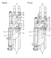
- the tractor 1 shows a tractor 1 to which a charger 2 is coupled is.
- the tractor 1 has two support brackets 11 arranged on the side formed, which assigned to the charger 2 arranged support brackets 21 are, the support brackets 11 and 21 with mutually associated coupling elements are provided, by means of which the charger 2 to the tractor 1 can be automatically coupled and locked.
- the tractor 1 and 2 charger plates provided on the charger, through which the hydraulic Control system of the charger 2 to the hydraulic system of the tractor 1 can be connected manually.
- a first coupling plate 31 is rigidly attached to the support bracket 11 provided on the tractor 1. Lines 32 leading to the hydraulic system of the tractor 1 are connected to this coupling plate 31.
- an actuating element 4 which surrounds the coupling plate 31 in a U-shape, is also provided and can be displaced vertically relative to the coupling plate 31 by means of a hydraulic actuating cylinder 41.
- the control element 4 is formed at its upper end with two catch hooks 42, which are formed with guide slots 43.
- a bolt 44 is also fastened, which passes through the adjusting element 4 in two slots 45 and on which a latching hook 46 is pivotally mounted.
- the latching hook 46 is formed with a guide surface 47 to which an adjusting bolt 48 arranged on the adjusting element 4 is assigned.
- four bolts 49 protrude from the inside of the actuating element 4.
- the adjusting element 4 can be adjusted in height by means of the adjusting cylinder 41.
- the actuating element 4 is guided through the slots 45, which are penetrated by the bolt 44, and through the tab 13, which slides along the guide plate 12.
- the one assigned to the coupling plate 31 of the carrier vehicle 1 on the charger 2 Coupling plate 51 is arranged on a carrier 5. Of this Coupling plate 51 go off hydraulic lines 52, which for hydraulic Lead charger 2 system.
- the clutch plate 51 is further formed with a transversely protruding bolt 53 through which they mounted on the support 5 so as to be pivotable about an approximately horizontal axis is. The pivotability is provided by a bolt provided on the support 5 56 limited.
- On the bracket 21 of the charger 2 is a swing arm 6 mounted, which is pivotable about an approximately horizontally aligned axis 61 is.
- An actuating rod 62 is articulated to the swing arm 6, which its effective length is adjustable and which by a helical compression spring 63 is surrounded.
- the carrier 5 is longitudinal by means of a tab 54 of the swing arm 6 slidably, it by means of a braking device 55 remains in the respective position.
- the actuating element 4 is then moved downwards by means of the actuating cylinder 41, the adjusting pin 48 along the vertical portion of the Guide surface 47 of the locking hook 46 moves, causing this in its position remains. This situation is shown in Fig. 3c. By another move comes the bottom of the clutch plate 51 on top of the clutch plate 31 to support, whereby the two hydraulic systems together are coupled.
- the mechanical uncoupling takes place first by means of the hydraulic systems.
- the two clutch plates 31 and 51 are uncoupled from one another in that the actuating element 4 is displaced upward by means of the actuating cylinder 41.
- the latching hook 46 is pivoted in the counterclockwise direction by the adjusting bolt 48 which interacts with the guide surface 47, as a result of which the two ends of the supporting bolt 53 are released.
- the carrier 5 for the clutch plate 51 can be raised by the actuator 4 by a further upward movement of the adjusting element 4, whereby the clutch plate 51 is released from the clutch plate 31.
- the carrier 5 for the clutch plate 51 slides along the swing arm 6 upwards.
- the tractor 1 can be moved completely away from the charger 2. Due to the braking device 55, the carrier 5 remains at the height at which the uncoupling has taken place, whereby a subsequent clutch is facilitated.
Landscapes
- Engineering & Computer Science (AREA)
- Mechanical Engineering (AREA)
- Mining & Mineral Resources (AREA)
- Civil Engineering (AREA)
- General Engineering & Computer Science (AREA)
- Structural Engineering (AREA)
- Agricultural Machines (AREA)
- Quick-Acting Or Multi-Walled Pipe Joints (AREA)
- Lifting Devices For Agricultural Implements (AREA)
- Auxiliary Drives, Propulsion Controls, And Safety Devices (AREA)
- Arrangement And Driving Of Transmission Devices (AREA)
- Automobile Manufacture Line, Endless Track Vehicle, Trailer (AREA)
- Forklifts And Lifting Vehicles (AREA)
- Current-Collector Devices For Electrically Propelled Vehicles (AREA)
- Preliminary Treatment Of Fibers (AREA)
Applications Claiming Priority (2)
| Application Number | Priority Date | Filing Date | Title |
|---|---|---|---|
| AT0078702A AT412976B (de) | 2002-05-23 | 2002-05-23 | Einrichtung zur kupplung der an einem tragfahrzeug und einer diesem zugeordneten ladeeinrichtung angeordneten kupplungselemente für das hydraulische betätigungssystem |
| AT7872002 | 2002-05-23 |
Publications (2)
| Publication Number | Publication Date |
|---|---|
| EP1365074A1 EP1365074A1 (de) | 2003-11-26 |
| EP1365074B1 true EP1365074B1 (de) | 2004-12-15 |
Family
ID=3680935
Family Applications (1)
| Application Number | Title | Priority Date | Filing Date |
|---|---|---|---|
| EP03450083A Expired - Lifetime EP1365074B1 (de) | 2002-05-23 | 2003-04-10 | Einrichtung zur hydraulischen Kupplung von einer Ladeeinrichtung an einem Tragfahrzeug |
Country Status (6)
| Country | Link |
|---|---|
| EP (1) | EP1365074B1 (pl) |
| AT (2) | AT412976B (pl) |
| DE (1) | DE50300203D1 (pl) |
| HR (1) | HRP20030315B1 (pl) |
| NO (1) | NO20031798L (pl) |
| PL (1) | PL359737A1 (pl) |
Families Citing this family (15)
| Publication number | Priority date | Publication date | Assignee | Title |
|---|---|---|---|---|
| FR2871485B1 (fr) * | 2004-06-10 | 2006-09-01 | Etude Et D Innovation Dans Le | Dispositif d'accouplement d'un chargeur sur un tracteur |
| DE102004037459A1 (de) * | 2004-08-02 | 2006-02-23 | Liebherr-Hydraulikbagger Gmbh | Hydraulikschnellkupplung |
| DE102006003768A1 (de) * | 2006-01-25 | 2007-07-26 | Wilhelm Stoll Maschinenfabrik Gmbh | Frontlader und Traktorkabine für einen Traktor |
| DE202006005203U1 (de) | 2006-03-31 | 2007-08-09 | Liebherr-Hydraulikbagger Gmbh | Schnellkupplung |
| DE102007034207B4 (de) * | 2007-07-23 | 2009-06-10 | Pauly, Jürgen | Rahmen zur Befestigung einer Anbauvorrichtung an einem Lastkraftwagen |
| AT506554B1 (de) * | 2008-03-20 | 2011-11-15 | Alois Ing Wimmer | Kupplungsvorrichtung mit einer einrichtung zum automatischen verbinden von energieleitungen |
| SE532822C2 (sv) * | 2008-07-07 | 2010-04-13 | Nordhydraulic Ab | Ventilfäste |
| CH699404A1 (de) * | 2008-08-25 | 2010-02-26 | Josef Martin Gmbh & Co Kg | Energieträgerkupplung, sowie Kupplung mit Energieträgerkupplung. |
| CN103397670A (zh) * | 2013-07-13 | 2013-11-20 | 临颍县颍机机械制造有限公司 | 配履带拖拉机装载装置 |
| DE102014002376B3 (de) * | 2013-12-18 | 2015-04-02 | Thomas Mösl | Automatisches Kupplungssystem und Fahrzeug mit einem solchen Kupplungssystem |
| US9375988B2 (en) * | 2014-10-22 | 2016-06-28 | Deere & Company | Coupling mechanism |
| IT201800002352A1 (it) * | 2018-02-02 | 2019-08-02 | Faster Spa | Attacco idraulico e/o pneumatico, in particolare del tipo a connessioni multiple |
| CA3103021C (en) | 2018-06-15 | 2023-11-21 | Clark Equipment Company | Hydraulic coupling |
| DE102020006487A1 (de) | 2020-10-20 | 2022-04-21 | Dürr Somac GmbH | Schnellwechseleinrichtung für einen Fülladapter |
| DE102022126522A1 (de) | 2022-10-12 | 2024-04-18 | Liebherr-France Sas | Arbeitsmaschine mit Kupplungsvorrichtung für fluidführende Leitungen |
Family Cites Families (6)
| Publication number | Priority date | Publication date | Assignee | Title |
|---|---|---|---|---|
| US4738463A (en) * | 1987-02-24 | 1988-04-19 | Deere & Company | Automatically coupling fluid connector for a hitch |
| FR2645242B1 (fr) * | 1989-03-29 | 1991-08-23 | Etud Innovation Mat Agricole | Connecteur fluidique multiple |
| FR2684120B1 (fr) * | 1991-11-27 | 1998-08-07 | Emily Ets | Systeme d'accouplement et de desaccouplement d'un chargeur a commande hydraulique pour tracteurs agricoles ou autres. |
| FR2687115B1 (fr) * | 1992-02-07 | 1998-05-22 | Emily Sa Ets | Systeme d'accouplement et de desaccouplement a un vehicule d'un accessoire disposant d'organes a commande hydraulique ou pneumatique. |
| JP3452089B2 (ja) * | 1994-08-08 | 2003-09-29 | 三陽機器株式会社 | 作業機車両の継手脱着装置 |
| SE9600570D0 (sv) * | 1996-02-16 | 1996-02-16 | Aaloe Maskiner Ab | Ett kombinerat ventilhus och snabbkoppling |
-
2002
- 2002-05-23 AT AT0078702A patent/AT412976B/de not_active IP Right Cessation
-
2003
- 2003-04-10 AT AT03450083T patent/ATE285001T1/de not_active IP Right Cessation
- 2003-04-10 DE DE50300203T patent/DE50300203D1/de not_active Expired - Fee Related
- 2003-04-10 EP EP03450083A patent/EP1365074B1/de not_active Expired - Lifetime
- 2003-04-16 PL PL03359737A patent/PL359737A1/pl not_active IP Right Cessation
- 2003-04-22 NO NO20031798A patent/NO20031798L/no not_active Application Discontinuation
- 2003-04-22 HR HR20030315A patent/HRP20030315B1/xx not_active IP Right Cessation
Also Published As
| Publication number | Publication date |
|---|---|
| NO20031798L (no) | 2003-11-24 |
| PL359737A1 (pl) | 2003-12-01 |
| ATE285001T1 (de) | 2005-01-15 |
| EP1365074A1 (de) | 2003-11-26 |
| DE50300203D1 (de) | 2005-01-20 |
| HRP20030315B1 (en) | 2005-10-31 |
| HRP20030315A2 (en) | 2004-08-31 |
| NO20031798D0 (no) | 2003-04-22 |
| ATA7872002A (de) | 2005-02-15 |
| AT412976B (de) | 2005-09-26 |
Similar Documents
| Publication | Publication Date | Title |
|---|---|---|
| EP1365074B1 (de) | Einrichtung zur hydraulischen Kupplung von einer Ladeeinrichtung an einem Tragfahrzeug | |
| EP0649765A1 (de) | Betätigungseinrichtung für ein Verdeck und einen Verdeckkastendeckel eines Kraftfahrzeuges | |
| EP1884410A2 (de) | Hecklastenträger | |
| WO2019180017A1 (de) | System und verfahren zum verschwenken einer kopplungskomponente | |
| DE4240790C1 (de) | Scharnier für eine hochschwenkbare Abdeckhaube eines Kraftwagens | |
| EP1243466B1 (de) | Transportsicherung für Frachtcontainer | |
| DE19812835B4 (de) | Fanghaken-Betätigungsanordnung für Motorhauben von Kraftfahrzeugen | |
| EP1101869B1 (de) | Schwellengreifer | |
| EP1528164B1 (de) | Vorrichtung zur lösbaren Kupplung eines Arbeitsgerätes, insbesondere einer Ladeschwinge, mit einem Tragfahrzeug | |
| DE102021104519B4 (de) | Vorrichtung zum Öffnen und Verschließen einer Zugriffsöffnung in einer Fahrzeugkarosserie | |
| DE564371C (de) | Anhaengerkupplung fuer Sattelschlepper | |
| DE4326305C2 (de) | Landwirtschaftliche Erntemaschine | |
| EP0572886B1 (de) | Abflussregler für Ausläufe aus Flüssigkeitsbehältern | |
| DE2638483C3 (de) | Vorrichtung zur Fernbedienung der Verriegelungseinrichtung einer selbsttätigen Anhangerkupplung | |
| DE10123790A1 (de) | Vorrichtung zum Öffnen und Schließen des Aufstelldachs an Aufstelldachfahrzeugen | |
| DE1812995A1 (de) | Filterpresse mit einer Einrichtung zum Loesen und Kuppeln der Filterplatten | |
| EP4268562B1 (de) | Landwirtschaftliches anbaugerät | |
| DE2731332C2 (de) | Schwenkvorrichtung für Fahrzeugscheinwerfer | |
| DE1756032A1 (de) | UEberfahrbruecke fuer Rampen | |
| DE20022769U1 (de) | Schwellengreifer | |
| EP1607259B1 (de) | Abdeckeinheit mit einem verschwenkbaren Verdeckkastendeckel für einen Verdeckkasten eines Fahrzeugs | |
| EP0533081A1 (de) | Anhängevorrichtung für Zugmaschinen | |
| DE4309347C2 (de) | Umstellbare Steuerstange für Bremsgestängesteller eines Schienenfahrzeugs | |
| EP0450604A1 (de) | Vorrichtung zum An- und Abkoppeln eines Saugrohres an den Füllstutzen eines Fassbehälters | |
| DE1924832C (de) | Oberblock verstelleinrichtung |
Legal Events
| Date | Code | Title | Description |
|---|---|---|---|
| PUAI | Public reference made under article 153(3) epc to a published international application that has entered the european phase |
Free format text: ORIGINAL CODE: 0009012 |
|
| AK | Designated contracting states |
Kind code of ref document: A1 Designated state(s): AT BE BG CH CY CZ DE DK EE ES FI FR GB GR HU IE IT LI LU MC NL PT RO SE SI SK TR |
|
| AX | Request for extension of the european patent |
Extension state: AL LT LV MK |
|
| 17P | Request for examination filed |
Effective date: 20031126 |
|
| 17Q | First examination report despatched |
Effective date: 20040220 |
|
| GRAP | Despatch of communication of intention to grant a patent |
Free format text: ORIGINAL CODE: EPIDOSNIGR1 |
|
| AKX | Designation fees paid |
Designated state(s): AT BE BG CH CY CZ DE DK EE ES FI FR GB GR HU IE IT LI LU MC NL PT RO SE SI SK TR |
|
| GRAS | Grant fee paid |
Free format text: ORIGINAL CODE: EPIDOSNIGR3 |
|
| GRAA | (expected) grant |
Free format text: ORIGINAL CODE: 0009210 |
|
| AK | Designated contracting states |
Kind code of ref document: B1 Designated state(s): AT BE BG CH CY CZ DE DK EE ES FI FR GB GR HU IE IT LI LU MC NL PT RO SE SI SK TR |
|
| PG25 | Lapsed in a contracting state [announced via postgrant information from national office to epo] |
Ref country code: TR Free format text: LAPSE BECAUSE OF FAILURE TO SUBMIT A TRANSLATION OF THE DESCRIPTION OR TO PAY THE FEE WITHIN THE PRESCRIBED TIME-LIMIT Effective date: 20041215 Ref country code: SK Free format text: LAPSE BECAUSE OF FAILURE TO SUBMIT A TRANSLATION OF THE DESCRIPTION OR TO PAY THE FEE WITHIN THE PRESCRIBED TIME-LIMIT Effective date: 20041215 Ref country code: SI Free format text: LAPSE BECAUSE OF FAILURE TO SUBMIT A TRANSLATION OF THE DESCRIPTION OR TO PAY THE FEE WITHIN THE PRESCRIBED TIME-LIMIT Effective date: 20041215 Ref country code: RO Free format text: LAPSE BECAUSE OF FAILURE TO SUBMIT A TRANSLATION OF THE DESCRIPTION OR TO PAY THE FEE WITHIN THE PRESCRIBED TIME-LIMIT Effective date: 20041215 Ref country code: NL Free format text: LAPSE BECAUSE OF FAILURE TO SUBMIT A TRANSLATION OF THE DESCRIPTION OR TO PAY THE FEE WITHIN THE PRESCRIBED TIME-LIMIT Effective date: 20041215 Ref country code: IT Free format text: LAPSE BECAUSE OF FAILURE TO SUBMIT A TRANSLATION OF THE DESCRIPTION OR TO PAY THE FEE WITHIN THE PRESCRIBED TIME-LIMIT;WARNING: LAPSES OF ITALIAN PATENTS WITH EFFECTIVE DATE BEFORE 2007 MAY HAVE OCCURRED AT ANY TIME BEFORE 2007. THE CORRECT EFFECTIVE DATE MAY BE DIFFERENT FROM THE ONE RECORDED. Effective date: 20041215 Ref country code: IE Free format text: LAPSE BECAUSE OF FAILURE TO SUBMIT A TRANSLATION OF THE DESCRIPTION OR TO PAY THE FEE WITHIN THE PRESCRIBED TIME-LIMIT Effective date: 20041215 Ref country code: GB Free format text: LAPSE BECAUSE OF FAILURE TO SUBMIT A TRANSLATION OF THE DESCRIPTION OR TO PAY THE FEE WITHIN THE PRESCRIBED TIME-LIMIT Effective date: 20041215 Ref country code: FR Free format text: LAPSE BECAUSE OF FAILURE TO SUBMIT A TRANSLATION OF THE DESCRIPTION OR TO PAY THE FEE WITHIN THE PRESCRIBED TIME-LIMIT Effective date: 20041215 Ref country code: FI Free format text: LAPSE BECAUSE OF FAILURE TO SUBMIT A TRANSLATION OF THE DESCRIPTION OR TO PAY THE FEE WITHIN THE PRESCRIBED TIME-LIMIT Effective date: 20041215 Ref country code: EE Free format text: LAPSE BECAUSE OF FAILURE TO SUBMIT A TRANSLATION OF THE DESCRIPTION OR TO PAY THE FEE WITHIN THE PRESCRIBED TIME-LIMIT Effective date: 20041215 Ref country code: CZ Free format text: LAPSE BECAUSE OF FAILURE TO SUBMIT A TRANSLATION OF THE DESCRIPTION OR TO PAY THE FEE WITHIN THE PRESCRIBED TIME-LIMIT Effective date: 20041215 Ref country code: BG Free format text: LAPSE BECAUSE OF FAILURE TO SUBMIT A TRANSLATION OF THE DESCRIPTION OR TO PAY THE FEE WITHIN THE PRESCRIBED TIME-LIMIT Effective date: 20041215 |
|
| REG | Reference to a national code |
Ref country code: GB Ref legal event code: FG4D Free format text: NOT ENGLISH Ref country code: CH Ref legal event code: EP |
|
| REG | Reference to a national code |
Ref country code: IE Ref legal event code: FG4D Free format text: GERMAN |
|
| REF | Corresponds to: |
Ref document number: 50300203 Country of ref document: DE Date of ref document: 20050120 Kind code of ref document: P |
|
| PG25 | Lapsed in a contracting state [announced via postgrant information from national office to epo] |
Ref country code: SE Free format text: LAPSE BECAUSE OF FAILURE TO SUBMIT A TRANSLATION OF THE DESCRIPTION OR TO PAY THE FEE WITHIN THE PRESCRIBED TIME-LIMIT Effective date: 20050315 Ref country code: GR Free format text: LAPSE BECAUSE OF FAILURE TO SUBMIT A TRANSLATION OF THE DESCRIPTION OR TO PAY THE FEE WITHIN THE PRESCRIBED TIME-LIMIT Effective date: 20050315 Ref country code: DK Free format text: LAPSE BECAUSE OF FAILURE TO SUBMIT A TRANSLATION OF THE DESCRIPTION OR TO PAY THE FEE WITHIN THE PRESCRIBED TIME-LIMIT Effective date: 20050315 |
|
| PG25 | Lapsed in a contracting state [announced via postgrant information from national office to epo] |
Ref country code: HU Free format text: LAPSE BECAUSE OF FAILURE TO SUBMIT A TRANSLATION OF THE DESCRIPTION OR TO PAY THE FEE WITHIN THE PRESCRIBED TIME-LIMIT Effective date: 20050316 |
|
| PG25 | Lapsed in a contracting state [announced via postgrant information from national office to epo] |
Ref country code: ES Free format text: LAPSE BECAUSE OF FAILURE TO SUBMIT A TRANSLATION OF THE DESCRIPTION OR TO PAY THE FEE WITHIN THE PRESCRIBED TIME-LIMIT Effective date: 20050326 |
|
| PG25 | Lapsed in a contracting state [announced via postgrant information from national office to epo] |
Ref country code: CY Free format text: LAPSE BECAUSE OF FAILURE TO SUBMIT A TRANSLATION OF THE DESCRIPTION OR TO PAY THE FEE WITHIN THE PRESCRIBED TIME-LIMIT Effective date: 20050410 Ref country code: LU Free format text: LAPSE BECAUSE OF NON-PAYMENT OF DUE FEES Effective date: 20050410 Ref country code: AT Free format text: LAPSE BECAUSE OF NON-PAYMENT OF DUE FEES Effective date: 20050410 |
|
| PG25 | Lapsed in a contracting state [announced via postgrant information from national office to epo] |
Ref country code: MC Free format text: LAPSE BECAUSE OF NON-PAYMENT OF DUE FEES Effective date: 20050430 Ref country code: BE Free format text: LAPSE BECAUSE OF NON-PAYMENT OF DUE FEES Effective date: 20050430 |
|
| NLV1 | Nl: lapsed or annulled due to failure to fulfill the requirements of art. 29p and 29m of the patents act | ||
| PGFP | Annual fee paid to national office [announced via postgrant information from national office to epo] |
Ref country code: DE Payment date: 20050601 Year of fee payment: 3 |
|
| GBV | Gb: ep patent (uk) treated as always having been void in accordance with gb section 77(7)/1977 [no translation filed] |
Effective date: 20041215 |
|
| REG | Reference to a national code |
Ref country code: IE Ref legal event code: FD4D |
|
| PLBE | No opposition filed within time limit |
Free format text: ORIGINAL CODE: 0009261 |
|
| STAA | Information on the status of an ep patent application or granted ep patent |
Free format text: STATUS: NO OPPOSITION FILED WITHIN TIME LIMIT |
|
| BERE | Be: lapsed |
Owner name: HAUER, FRANZ Effective date: 20050430 |
|
| 26N | No opposition filed |
Effective date: 20050916 |
|
| EN | Fr: translation not filed | ||
| PG25 | Lapsed in a contracting state [announced via postgrant information from national office to epo] |
Ref country code: DE Free format text: LAPSE BECAUSE OF NON-PAYMENT OF DUE FEES Effective date: 20061101 |
|
| REG | Reference to a national code |
Ref country code: CH Ref legal event code: PL |
|
| BERE | Be: lapsed |
Owner name: *HAUER FRANZ Effective date: 20050430 |
|
| PG25 | Lapsed in a contracting state [announced via postgrant information from national office to epo] |
Ref country code: PT Free format text: LAPSE BECAUSE OF NON-PAYMENT OF DUE FEES Effective date: 20050515 |
|
| PG25 | Lapsed in a contracting state [announced via postgrant information from national office to epo] |
Ref country code: CH Free format text: LAPSE BECAUSE OF NON-PAYMENT OF DUE FEES Effective date: 20070430 Ref country code: LI Free format text: LAPSE BECAUSE OF NON-PAYMENT OF DUE FEES Effective date: 20070430 |