EP1364169B1 - Lüftereinheit - Google Patents
Lüftereinheit Download PDFInfo
- Publication number
- EP1364169B1 EP1364169B1 EP01914318A EP01914318A EP1364169B1 EP 1364169 B1 EP1364169 B1 EP 1364169B1 EP 01914318 A EP01914318 A EP 01914318A EP 01914318 A EP01914318 A EP 01914318A EP 1364169 B1 EP1364169 B1 EP 1364169B1
- Authority
- EP
- European Patent Office
- Prior art keywords
- guide
- airflow
- fan unit
- guide surface
- fan
- Prior art date
- Legal status (The legal status is an assumption and is not a legal conclusion. Google has not performed a legal analysis and makes no representation as to the accuracy of the status listed.)
- Expired - Lifetime
Links
Images


Definitions
- the present invention relates to a fan unit.
- the problem associated with fan filter noise is particularly exacerbated in confined spaces or enclosures such as a multi-storey wafer fabrication plant.
- the present invention envisages the height of the ceiling to be less than three meters. Low ceilings cause noise from fan filter unit to be particularly pronounced.
- a fan unit which can be used regardless of whether the fan rotates in anticlockwise or clockwise direction by using a pair of guides disposed on opposite sides of the fan blower in an airflow plane to guide the flow of air between the two guides, each guide having an indent opposite the fan to accommodate the fan and each guide being symmetric about a symmetry plane perpendicular to the air flow plane formed through the centre of the fan and an indent.
- the guides have a substantially W-type shape.
- the S-shaped or W-shaped guides are relatively bulky and complex to manufacture and install. The present inventors have sought to provide a fan unit for reducing noise without increasing contamination in the airflow through the unit, which fan unit is easy to manufacture and has high power efficiency.
- the present invention accordingly provides a fan unit as claimed in claim 1.
- construction of the fan unit becomes very simple. A wide variety of configurations can be constructive from a relatively small number of parts.
- Each guide surface may be made of any suitable shape. It may be curved or straight.
- the first and second airflow paths are defined on the radially outer side by the guide surfaces and on the radially inner side by the periphery of the fan blower.
- the airflow paths may be of any suitable configuration. They may be straight, but preferably, the airflow paths are curved. Preferably, the airflow paths diverge in the angular direction of rotation of the fan blower.
- the first or second airflow path may be defined on its radially outer side solely by the respective pair of guides. Alternatively, there may be additional guides which define a further part of the airflow path.
- the fan unit comprises a first wall means on the first side of the fan blower, the first guide surface touching the first wall means at a first point and the second guide surface touching the first wall means at a second point displaced from the first point, so that the portion of first wall means between the first and second points effectively defines a further guide surface.
- a second wall means on the second side of the fan blower the third guide surface touching the second wall means at a first point and the fourth guide surface touching the second wall means at a second point displaced from the first point so that the portion of the second wall means between the first and second points effectively defines a further guide surface.
- the first guide means including the first guide surface
- the second guide means including the second guide surface
- the third guide means including the third guide surface
- the fourth guide means including the fourth guide surface
- each respective guide means comprises an additional guide surface, facing in a different direction to the respective one of the first, second, third and fourth guide surfaces.
- the additional guide surfaces of the guide means help to provide a streamline flow path at the point where the air flow path enters the air flow channel.
- At least the first and third guide means are identical to one another and preferably all of the guide means are identical to each other. This particularly simplifies manufacture and construction as only one type of guide means needs to be manufactured.
- the guide surfaces and, where present, additional guide surfaces of each guide means are of any suitable configuration, being preferably straight or curved.
- the transition from a guide surface to the additional guide surface may be defined by a point. However, it is preferably defined by a smoothly curving transitional surface, to improve airflow and noise reduction.
- the first guide surface is closer to the axis of the fan blower than the second guide surface.
- the third guide surface is preferably closer to the axis of the fan blower than the fourth guide surface. In this way, diverging flow paths can be provided.
- the first and third guide surfaces are located at the same distance from the axis of the fan blower and the fourth and second guide surfaces are located at the same distance from the axis of the fan blower as one another. In this way, a rotationally symmetrical arrangement is obtained.
- the fan blower must rotate in the correct direction in order to work.
- the fan blower must rotate in the direction of increasing air flow path width.
- the guide means are identical and each guide means is symmetrical about a mirror plane passing through the transition so that it has a guide surface and an additional surface, the additional surface is substantially being identical to the guide surface.
- the guide means can then be repositioned relatively easily so that the arrangement of the guide surfaces is appropriate to the fan rotating in the opposite direction.
- the arrangement of the guide surfaces should be a mirror image of the arrangement of the guide surfaces with the fan rotating in the first direction, with the mirror plane passing through the axis of the fan blower.
- the first and second airflow channels each lead to a first baffle arranged at an angle to the direction of the airflow to deflect the airflow.
- the airflow is directed in a downward direction.
- the vertical direction is taken to be the direction perpendicular to the plane of air emitted from the fan.
- the first and second airflow channels each comprise a second baffle arranged at an angle to the direction of the flow coming from the first baffle to further deflect the flow.
- the second baffle is mounted below the first baffle. Together, the first and second baffles deflect the respective airflow through an angle in the range 90°-180°, with a minimum of turbulence.
- the first and second baffles are preferably inclined with respect to one another, such that the distance between the baffles decreases in a linear direction away from the fan.
- the baffles are located such that, as the air leaves the guides, the air is deflected by the first baffle onto the second baffle, the second baffle being positioned to direct the air out of an outlet.
- first baffle or the second baffle and most preferably both of them comprise perforated material to improve sound absorption.
- the first baffle is arranged at an angle of from 40° to 60°, preferably 45° to the plane of the airflow.
- the second baffle is disposed at an angle of 5° to 15°, preferably 10° to the plane of the airflow from the fan.
- the first and second airflow channels each comprise a final baffle for deflecting the airflow.
- the final baffle deflects the airflow in a downward direction.
- the final baffle is mounted beneath the fan blower.
- the final baffles for the first and second airflow channels abut one another to form a generally V shaped structure.
- the fan unit comprises a housing.
- the fan blowers and the guide surfaces are disposed on a base plate.
- the unit further comprises a top housing coupled to the base plate with an inlet for drawing air into the fan, the fan and guides being located between the upper housing and the base plate.
- the housing comprises side sections, an air outlet communicating with a respective airflow channel being formed by a gap between the base, side sections and top housing.
- the side sections comprise wall means as described above. The side sections may be integral with the top housing.
- the further baffles are at least partly located in the gap between the side sections and the base plate.
- the base plate will preferably be located relative to the housing such that the separation between the base plate and the upper surface of the upper housing is smaller than the distance by which the side sections protrude from the upper surface of the housing. There is also a gap between the side sections and the base plate to form the outlet of the fan unit.
- the gap between the side sections of the housing and the base plate should, ideally be large enough to accommodate at least a part of the lower baffle in this gap.
- the fan unit comprises a filter.
- the configuration of the guides reduces the noise from the fan unit. Also, the configuration of the guides enhances the velocity of air circulating in the unit. Hence, a more efficient fan unit can be produced as a lower power can be used to drive the fan to achieve the same circulating air velocity.
- the fan unit of the present invention is primarily intended for use in a clean room. Therefore, the unit preferably comprises a filter. Generally, this filter will be located below the base plate of the unit.
- the guides and/or the baffles of the present invention will preferably be made from a solid material, more preferably a metal.
- the guides and/or baffles may also be perforated.
- the fan unit of the present invention preferably does not comprise conventional sound insulation material in contact with the airflow flowing through the unit. Sound insulation material may be included in the fan unit, but is preferably separated from the airflow by a solid structure, such as a baffle or wall means.
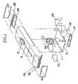
- FIG. 1 shows an exploded view of the fan filter unit. For clarity, the filter is not shown.
- a rotatable fan blower 12 is located on a base plate 14.
- a mounting plate 20 for the fan blower 12 is located on an opposing side of the base plate 14 to the fan blower 12.
- the fan blower 12 is located within a housing which is formed from the base plate 14, an upper housing 16 and end sections 22.
- the upper housing 16 has an air inlet 18 located in its centre, such that in use, the air inlet is located above fan blower 12.
- Fan blower 12 is a conventional type blower. It is configured to be rotated by a motor (not shown) which will be located on opposing side of base plate 14 to the fan blower 12. As the fan blower rotates, it air is drawn through inlet 18 and expelled air in direction tangential to the rotation direction of the fan blower 12.
- the fan blower is also provided with first and second guide means 24A and 24B on one side and third and fourth guide means 24C and 24D on the other side.
- the shape of the guide means will be described further below in relation to Figure 3.
- Upper baffles 26A and 26B and lower baffles 28A and 28B are provided at either end of the unit, such that the baffles are disposed between fan blower 12, guide means 24A, and 24B and 24C and 24D and the end section 22.
- FIG 2 shows the direction of air flow within the fan filter of Figure 1.
- air is drawn in through inlet 18 by the rotation of fan blower 12.
- Fan blower 12 is located on base plate 14.
- the rotation of the fan blower forces air away from the fan blower and into the baffles 26A and 26B and 28A and 28B.
- the direction of the baffles turns the air from travelling away from the blower which is located on the base plate to travelling out of the outlet 19 which is located beneath the base plate 14. The air then travels through filter 32 which is located underneath opening 19.
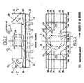
- FIG 3 shows a plan view of the constructed fan filter unit of Figures 1 and 2.
- the fan blower 12 is located in a space between the guide means 24A, 24B, 24C and 24D.
- On one side of the fan filter unit there is a first guide surface 27A and a second guide surface 27B.
- the guide surfaces define a radially outer boundary of an airflow path of which leads, through constriction 30, to the upper baffle 26B.
- a third guide surface 27C and a fourth guide surface 27D are provided on the other side of the fan blower, and together with a part of the wall 25B between them, define the radially outer boundary of a second flow path which leads through constriction 31 to the upper baffle 26A.
- each guide means comprises an additional guide surface 32A, 32B, 32C and 32D respectively. It can be seen that the additional guide surfaces 32A and 32C define between them a diverging flow path leading from constriction 31. Additional guide surface 32B and 32D define between them a diverging flow path leading from constriction 30.
- the guide means 24A, 24B, 24C and 24D are identical in shape to the other guide means. Each comprises a smoothly curving guide surface and a smoothly curving additional guide surface with a smoothly curving transitional zone 33 between them. This smoothly curving transitional zone is provided to reduce turbulence and improve airflow velocity. It is also apparent from Figure 3 that the distance a from the centre of the smoothly curving portion 33A to the centre line of the fan blower is less than the distance b of the transitional portion 33B from the centre line of the fan blower.
- the distance d of the transitional portion 33D from the centre line of the fan blower is less than the distance c of the centre of the transitional portion 33C from the centre line of the fan blower.
- the guides 24A, 24B, 24C and 24D are contoured to receive the discharged air from the fan blower 12 (shown in dotted circle) and guide the flow of air with minimum amount of turbulence towards the baffles 26 and 28. As this is a top view, the lower baffle 28 is not clearly shown.
- the upper baffles 26 are disposed at angles of about 45° to the plane of air which is emitted from blower 12, to diffuse air from the guides 24.
- the lower baffles 28 are disposed at an angle of about 10° to the airflow plane to redirect the flow of air below the base plate 14.
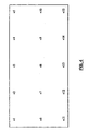
- Figures 4,5 and 6 show results from the fan unit.
- Figure 5 shows a plot of the air velocity averaged over measurements taken at 15 different points in the fan unit. The 15 locations within the fan unit are shown in Figure 4.
- figure 6 shows a plot of the noise level averaged over measurements taken at the same fifteen different points in the fan unit against rotation frequency of the fan blower.
- the noise level is measured at a distance one metre away from the fan, in decibels.
- the present invention allows a higher air velocity which provides enhanced air circling action with the same amount of driving power to the fan. Hence, the present invention provides considerable energy advantages to that of the prior art.
Landscapes
- Structures Of Non-Positive Displacement Pumps (AREA)
Claims (18)
- Gebläse-Einheit, die folgendes umfaßt:wobei die erste, die zweite, die dritte und die vierte Führungsfläche (27A, 27B, 27C, 27D) an gesonderten Führungsmitteln (24A, 24B, 24C, 24D) angebracht werdenein Windradgebläse (12), konfiguriert, um Luft in einer Vielzahl von Richtungen in einer Luftstromebene zu emittieren,eine erste und eine zweite Führungsfläche (27A, 27B), angeordnet an einer ersten Seite des Windradgebläses in der Luftstromebene, wobei die erste und die zweite Führungsfläche zusammen wenigstens teilweise die in Radialrichtung äußere Begrenzung einer ersten Luftstrombahn, die zu einem ersten Luftstromkanal führt, definieren,eine dritte und eine vierte Führungsfläche (27C, 27D), angeordnet an einer zweiten, gegenüberliegenden, Seite des Windradgebläses in der Luftstromebene, wobei die dritte und die vierte Führungsfläche zusammen wenigstens teilweise die in Radialrichtung äußere Begrenzung einer zweiten Luftstrombahn, die zu einem zweiten Luftstromkanal führt, definieren,
bei der die Gebläse-Einheit ein erstes Wandmittel (25A) an der ersten Seite des Windradgebläses umfaßt, wobei die erste Führungsfläche (27A) das erste Wandmittel (25A) an einem ersten Punkt berührt und die zweite Führungsfläche (27B) das erste Wandmittel (25A) an einem zweiten, vom ersten Punkt versetzten, Punkt berührt, und die Gebläse-Einheit ein zweites Wandmittel (25B) an der zweiten Seite des Windradgebläses umfaßt, wobei die dritte Führungsfläche (27C) das zweite Wandmittel (25B) an einem dritten Punkt berührt und die vierte Führungsfläche (27C) das zweite Wandmittel (25B) an einem vierten, vom dritten Punkt versetzten, Punkt berührt. - Gebläse-Einheit nach Anspruch 1, bei welcher der Abschnitt des ersten Wandmittels (25A) zwischen dem ersten und dem zweiten Punkt wirksam eine weitere Führungsfläche definiert.
- Gebläse-Einheit nach Anspruch 1, bei welcher der Abschnitt des zweiten Wandmittels (25B) zwischen dem dritten und dem vierten Punkt wirksam eine zweite weitere Führungsfläche definiert.
- Gebläse-Einheit nach Anspruch 1, bei der alle Führungsmittel (24A, 24B, 24C, 24D) zueinander identisch sind.
- Gebläse-Einheit nach Anspruch 2, bei der alle Führungsmittel (24A, 24B, 24C, 24D) zueinander identisch sind.
- Gebläse-Einheit nach Anspruch 3, bei der alle Führungsmittel (24A, 24B, 24C, 24D) zueinander identisch sind.
- Gebläse-Einheit nach Anspruch 1, bei welcher der erste und der zweite Luftstromkanal jeweils zu einer ersten Ablenkplatte (26A, 26B) führen, angeordnet in einem Winkel zur Richtung des Luftstroms, um den Luftstrom abzulenken.
- Gebläse-Einheit nach Anspruch 7, bei welcher der erste und der zweite Luftstromkanal außerdem eine zweite Ablenkplatte (28A, 28B) umfassen, angeordnet in einem Winkel zur Richtung des von der ersten Ablenkplatte (26A, 26B) kommenden Luftstroms, um den Strom weiter abzulenken.
- Gebläse-Einheit nach Anspruch 8, bei der wenigstens eine der ersten und zweiten Ablenkplatten (26A, 26B, 28A, 28B) ein perforiertes Material umfaßt.
- Gebläse-Einheit nach Anspruch 8, bei welcher der erste und der zweite Luftstromkanal jeweils eine Endablenkplatte umfassen, um den Luftstrom abzulenken.
- Gebläse-Einheit nach Anspruch 2, bei welcher der erste und der zweite Luftstromkanal jeweils zu einer ersten Ablenkplatte (26A, 26B) führen, angeordnet in einem Winkel zur Richtung des Luftstroms, um den Luftstrom abzulenken.
- Gebläse-Einheit nach Anspruch 3, bei welcher der erste und der zweite Luftstromkanal jeweils zu einer ersten Ablenkplatte (26A, 26B) führen, angeordnet in einem Winkel zur Richtung des Luftstroms, um den Luftstrom abzulenken
- Gebläse-Einheit nach Anspruch 1, bei der jedes Führungsmittel wesentlich symmetrisch um eine Spiegelebene ist, so daß das Führungsmittel (24A, 24B, 24C, 24D) eine erste Führungsfläche und eine wesentlich identische zusätzliche Führungsfläche umfaßt.
- Gebläse-Einheit nach Anspruch 2, bei der jedes Führungsmittel wesentlich symmetrisch um eine Spiegelebene ist, so daß das Führungsmittel (24A, 24B, 24C, 24D) eine erste Führungsfläche und eine wesentlich identische zusätzliche Führungsfläche umfaßt.
- Gebläse-Einheit nach Anspruch 3, bei der jedes Führungsmittel wesentlich symmetrisch um eine Spiegelebene ist, so daß das Führungsmittel (24A, 24B, 24C, 24D) eine erste Führungsfläche und eine wesentlich identische zusätzliche Führungsfläche umfaßt.
- Gebläse-Einheit nach Anspruch 4, bei der jedes Führungsmittel wesentlich symmetrisch um eine Spiegelebene ist, so daß das Führungsmittel (24A, 24B, 24C, 24D) eine erste Führungsfläche und eine wesentlich identische zusätzliche Führungsfläche umfaßt.
- Gebläse-Einheit nach Anspruch 7, bei der jedes Führungsmittel wesentlich symmetrisch um eine Spiegelebene ist, so daß das Führungsmittel (24A, 24B, 24C, 24D) eine erste Führungsfläche und eine wesentlich identische zusätzliche Führungsfläche umfaßt.
- Gebläse-Einheit nach Anspruch 10, bei der jedes Führungsmittel (24A, 24B, 24C, 24D) wesentlich symmetrisch um eine Spiegelebene ist, so daß das Führungsmittel eine erste Führungsfläche und eine wesentlich identische zusätzliche Führungsfläche umfaßt.
Applications Claiming Priority (1)
| Application Number | Priority Date | Filing Date | Title |
|---|---|---|---|
| PCT/SG2001/000027 WO2002068879A1 (en) | 2001-02-26 | 2001-02-26 | Fan unit |
Publications (2)
| Publication Number | Publication Date |
|---|---|
| EP1364169A1 EP1364169A1 (de) | 2003-11-26 |
| EP1364169B1 true EP1364169B1 (de) | 2004-09-01 |
Family
ID=29398797
Family Applications (1)
| Application Number | Title | Priority Date | Filing Date |
|---|---|---|---|
| EP01914318A Expired - Lifetime EP1364169B1 (de) | 2001-02-26 | 2001-02-26 | Lüftereinheit |
Country Status (3)
| Country | Link |
|---|---|
| EP (1) | EP1364169B1 (de) |
| JP (1) | JP4781609B2 (de) |
| DE (1) | DE60105321T2 (de) |
Families Citing this family (3)
| Publication number | Priority date | Publication date | Assignee | Title |
|---|---|---|---|---|
| JP6078269B2 (ja) * | 2012-08-30 | 2017-02-08 | 東プレ株式会社 | 送風ユニット |
| KR102250511B1 (ko) * | 2020-10-08 | 2021-05-11 | 삼성엔지니어링 주식회사 | 低 정압 팬필터유닛 및 이를 포함하는 클린룸 설비 |
| TWI771851B (zh) * | 2020-12-29 | 2022-07-21 | 惠亞工程股份有限公司 | 過濾設備 |
Family Cites Families (7)
| Publication number | Priority date | Publication date | Assignee | Title |
|---|---|---|---|---|
| US4560395A (en) * | 1984-04-17 | 1985-12-24 | Environmental Air Control, Inc. | Compact blower and filter assemblies for use in clean air environments |
| DE3438710C2 (de) * | 1984-10-23 | 1986-11-27 | Wilhelm Gebhardt Gmbh, 7112 Waldenburg | Dachventilator |
| JPH0782564B2 (ja) * | 1984-12-20 | 1995-09-06 | 富士通株式会社 | 紙幣鑑別センサのクリ−ニング装置 |
| JPH0726581Y2 (ja) * | 1989-07-05 | 1995-06-14 | 富士ロビン株式会社 | 遠心クラッチのシュー取付構造 |
| JPH0994419A (ja) * | 1995-09-29 | 1997-04-08 | Takasago Thermal Eng Co Ltd | ファンフィルタユニット |
| WO1999011984A1 (en) * | 1997-09-03 | 1999-03-11 | Kyodo-Allied Industries Ltd. | A method and apparatus for minimising noise from fan filter unit |
| JP3798981B2 (ja) * | 1999-09-30 | 2006-07-19 | キョードー−アライド・インダストリーズ・リミテッド | ファンユニットにおける騒音最小化装置 |
-
2001
- 2001-02-26 EP EP01914318A patent/EP1364169B1/de not_active Expired - Lifetime
- 2001-02-26 DE DE60105321T patent/DE60105321T2/de not_active Expired - Lifetime
- 2001-02-26 JP JP2002567751A patent/JP4781609B2/ja not_active Expired - Fee Related
Also Published As
| Publication number | Publication date |
|---|---|
| EP1364169A1 (de) | 2003-11-26 |
| DE60105321T2 (de) | 2005-09-29 |
| DE60105321D1 (de) | 2004-10-07 |
| JP2004522125A (ja) | 2004-07-22 |
| JP4781609B2 (ja) | 2011-09-28 |
Similar Documents
| Publication | Publication Date | Title |
|---|---|---|
| GB2354802A (en) | Airflow guide arrangement for minimising noise in a fan unit | |
| EP1216360B1 (de) | Vorrichtung zur geräuschverminderung eines gebläses | |
| KR100352431B1 (ko) | 창문형 에어컨의 터보팬 하우징 | |
| KR100293489B1 (ko) | 에어클리너 | |
| US6444004B1 (en) | Fan unit | |
| JP5915416B2 (ja) | 冷却室用エアカーテン装置 | |
| US6592451B2 (en) | Fan unit | |
| EP1364169B1 (de) | Lüftereinheit | |
| JP3612622B2 (ja) | 空気調和機用室内機 | |
| KR20000015827A (ko) | 에어컨디셔너용 옥외장치 | |
| JPH09133374A (ja) | 空気調和機 | |
| JPH0994419A (ja) | ファンフィルタユニット | |
| JP2003279072A (ja) | 送風機器および送風機器の吹出グリル | |
| EP1398575B1 (de) | Vorrichtung zur Geräuschminderung von einer Lüftereinheit | |
| JP3719368B2 (ja) | 送風機 | |
| CN215909338U (zh) | 室内机及具有其的空调器 | |
| CN1185448C (zh) | 风扇装置 | |
| KR100280008B1 (ko) | 시로코 팬의 컷오프 | |
| KR102284584B1 (ko) | 공기 조화기 실내기 및 개폐문 어셈블리 | |
| JP3820609B2 (ja) | トンネル式のクリーンルームのフィルタダクト形成方法 | |
| CN113932420A (zh) | 室内机及具有其的空调器 | |
| KR100234032B1 (ko) | 공기조화기의 저소음 소형화 구조 | |
| JP2001336779A (ja) | 空気清浄器 | |
| JPH09280614A (ja) | 空気清浄装置 | |
| KR20000004831U (ko) | 송풍기 유니트 |
Legal Events
| Date | Code | Title | Description |
|---|---|---|---|
| PUAI | Public reference made under article 153(3) epc to a published international application that has entered the european phase |
Free format text: ORIGINAL CODE: 0009012 |
|
| 17P | Request for examination filed |
Effective date: 20030210 |
|
| AK | Designated contracting states |
Kind code of ref document: A1 Designated state(s): AT BE CH CY DE DK ES FI FR GB GR IE IT LI LU MC NL PT SE TR |
|
| AX | Request for extension of the european patent |
Extension state: AL LT LV MK RO SI |
|
| GRAP | Despatch of communication of intention to grant a patent |
Free format text: ORIGINAL CODE: EPIDOSNIGR1 |
|
| RAP1 | Party data changed (applicant data changed or rights of an application transferred) |
Owner name: KYODO-ALLIED INDUSTRIES LTD |
|
| GRAS | Grant fee paid |
Free format text: ORIGINAL CODE: EPIDOSNIGR3 |
|
| GRAA | (expected) grant |
Free format text: ORIGINAL CODE: 0009210 |
|
| AK | Designated contracting states |
Kind code of ref document: B1 Designated state(s): DE GB |
|
| REG | Reference to a national code |
Ref country code: GB Ref legal event code: FG4D |
|
| REG | Reference to a national code |
Ref country code: IE Ref legal event code: FG4D |
|
| REF | Corresponds to: |
Ref document number: 60105321 Country of ref document: DE Date of ref document: 20041007 Kind code of ref document: P |
|
| LTIE | Lt: invalidation of european patent or patent extension |
Effective date: 20040901 |
|
| PLBE | No opposition filed within time limit |
Free format text: ORIGINAL CODE: 0009261 |
|
| STAA | Information on the status of an ep patent application or granted ep patent |
Free format text: STATUS: NO OPPOSITION FILED WITHIN TIME LIMIT |
|
| 26N | No opposition filed |
Effective date: 20050602 |
|
| PGFP | Annual fee paid to national office [announced via postgrant information from national office to epo] |
Ref country code: DE Payment date: 20120228 Year of fee payment: 12 |
|
| PGFP | Annual fee paid to national office [announced via postgrant information from national office to epo] |
Ref country code: GB Payment date: 20120224 Year of fee payment: 12 |
|
| GBPC | Gb: european patent ceased through non-payment of renewal fee |
Effective date: 20130226 |
|
| REG | Reference to a national code |
Ref country code: DE Ref legal event code: R119 Ref document number: 60105321 Country of ref document: DE Effective date: 20130903 |
|
| PG25 | Lapsed in a contracting state [announced via postgrant information from national office to epo] |
Ref country code: DE Free format text: LAPSE BECAUSE OF NON-PAYMENT OF DUE FEES Effective date: 20130903 Ref country code: GB Free format text: LAPSE BECAUSE OF NON-PAYMENT OF DUE FEES Effective date: 20130226 |