EP1363310A2 - Kathodenstrahlröhre, Vorrichtung mit Kathodenstrahlröhre, Bildanzeigegerät und Spuleneinheit - Google Patents
Kathodenstrahlröhre, Vorrichtung mit Kathodenstrahlröhre, Bildanzeigegerät und Spuleneinheit Download PDFInfo
- Publication number
- EP1363310A2 EP1363310A2 EP03252995A EP03252995A EP1363310A2 EP 1363310 A2 EP1363310 A2 EP 1363310A2 EP 03252995 A EP03252995 A EP 03252995A EP 03252995 A EP03252995 A EP 03252995A EP 1363310 A2 EP1363310 A2 EP 1363310A2
- Authority
- EP
- European Patent Office
- Prior art keywords
- loop coil
- glass bulb
- cathode
- ray tube
- color
- Prior art date
- Legal status (The legal status is an assumption and is not a legal conclusion. Google has not performed a legal analysis and makes no representation as to the accuracy of the status listed.)
- Withdrawn
Links
Images








Classifications
-
- H—ELECTRICITY
- H01—ELECTRIC ELEMENTS
- H01J—ELECTRIC DISCHARGE TUBES OR DISCHARGE LAMPS
- H01J29/00—Details of cathode-ray tubes or of electron-beam tubes of the types covered by group H01J31/00
- H01J29/46—Arrangements of electrodes and associated parts for generating or controlling the ray or beam, e.g. electron-optical arrangement
- H01J29/70—Arrangements for deflecting ray or beam
-
- H—ELECTRICITY
- H01—ELECTRIC ELEMENTS
- H01J—ELECTRIC DISCHARGE TUBES OR DISCHARGE LAMPS
- H01J29/00—Details of cathode-ray tubes or of electron-beam tubes of the types covered by group H01J31/00
- H01J29/003—Arrangements for eliminating unwanted electromagnetic effects, e.g. demagnetisation arrangements, shielding coils
-
- H—ELECTRICITY
- H01—ELECTRIC ELEMENTS
- H01J—ELECTRIC DISCHARGE TUBES OR DISCHARGE LAMPS
- H01J2229/00—Details of cathode ray tubes or electron beam tubes
- H01J2229/0007—Elimination of unwanted or stray electromagnetic effects
- H01J2229/003—Preventing or cancelling fields entering the enclosure
- H01J2229/0038—Active means
Definitions
- the present invention relates to a cathode-ray tube, a cathode-ray tube apparatus, an image display apparatus, and a coil unit, specifically to a technology of correcting an image displayed on the cathode-ray tube having been affected by the terrestrial magnetism.
- Color cathode-ray tube (CRT) apparatuses display images on the screen by allowing an electron gun to emit electron beams, which pass through passing holes of the color-selection electrode and reach the phosphor screen to which phosphors of red, green, and blue have been applied in advance at certain positions on which the electron beams are expected to land, allowing the phosphors at the landing positions to emit light of each color.
- an external magnetic field such as terrestrial magnetism (hereinafter, the external magnetic field is generically referred to as terrestrial magnetism) may act on the color CRT apparatuses to adversely affect the trajectory of the electron beams and inhibit the electron beams from landing on the phosphor screen at the expected positions. This is called “mislanding” or “landing deviation”, which results in color drifts or the like in the image displayed on the screen.
- a magnetic shield is provided in the CRTs.
- the magnetic shield it is difficult for the magnetic shield to remove a component of the terrestrial magnetism that is in parallel to the tube axial of the CRT (hereinafter, the component is referred to as tube axial component).
- the electron beams land on the phosphor screen shifting in a clockwise or counterclockwise rotation about the tube axial at the areas around the perimeter of the screen, depending on the direction of the magnetic pole of the affecting tube axial component of the terrestrial magnetism.
- the image on the screen viewed from outside appears to be tilting.
- color CRT apparatuses generally provide a function to adjust the image tilt.
- a loop coil 307 is wound around a funnel 303 of a glass bulb 305 constituting a CRT 301, where the loop coil 307 lies in a plane ⁇ that is perpendicular to a tube axial Z of the glass bulb 305.
- the value of the current that is fed through the loop coil 307 is adjusted using a variable resistor 309 connected to a direct voltage source 308, generating a magnetic field MC to cancel out a tube axial component MH of the terrestrial magnetism. With this operation, the image tilt is corrected.
- reference number 302 represents a face panel, 304 a neck, and 306 a deflection yoke.
- the above-described method is not a perfect solution to the screen image deficiency. That is to say, the magnetic field MC generated by the loop coil and the tube axial component MH of the terrestrial magnetism are not equal to each other in an opposite direction. As a result, though it may correct the image tilt in a visual check, it does not completely correct the landing deviation on the screen at the areas around the perimeter of the screen. That is to say, the color drift, a problem to be solved in improving the image quality, remains unsolved.
- Japanese Patent Publication No. 6-69221 discloses a color CRT apparatus that simultaneously performs the landing deviation correction and the image tilt adjustment.
- This technology corrects the image tilt and reduces the amount of landing deviation (that is to say, the amount of deviation of the electron beams, which have landed actually, from the positions on the screen at which the electron beams are expected to land when there is no effect by the terrestrial magnetism), by adjusting a position P of the loop coil 307 along the tube axial Z, which is originally disposed in a plane ⁇ that is perpendicular to the tube axial Z.
- the document discloses an observation result that when the position P of the loop coil 307 is shifted toward the deflection yoke 306 along the tube axial Z, the sensitivity of the tilt correction improves, and the amount of landing deviation correction decreases, and that on the contrary, when the position P of the loop coil 307 is shifted toward the face panel along the tube axial Z, the sensitivity of the tilt correction decreases, and the amount of landing deviation correction increases.
- the patent document proposes that an optimal position of the loop coil 307 is obtained in advance along the tube axial through experiments, and that the loop coil 307 is disposed at the obtained optimal position at which the amount of landing deviation becomes the smallest when the loop coil 307 receives a direct current as intense as decreases the image tilt to "0".
- the patent document states that it is possible to reduce the amount of landing deviation at the areas around the perimeter of the screen to a level that no color drift is observed, while correcting the image tilt.
- the first object of the present invention is therefore to provide a CRT that prevents the color drift over the whole screen by correcting the landing deviation accurately while at the same time adjusting the image tilt, canceling out the effect of the terrestrial magnetism.
- the second object of the present invention is to provide an image display apparatus having such a CRT.
- a cathode-ray tube comprising: a glass bulb including a face panel, a funnel, and a neck; a color-selection electrode which is disposed inside the face panel; and a loop coil which is disposed around the glass bulb between the color-selection electrode and a position at which a deflection yoke is to be attached, a predetermined level of direct current being fed through the loop coil, wherein the loop coil includes a first portion and a second portion, the first portion including two extending portions of the loop coil positioned over and below the glass bulb respectively, each center of the two extending portions being substantially in a plane perpendicular to a tube axial of the glass bulb, and the second portion including two bent portions that are formed by bending a right side and a left side of an original form of the loop coil toward the neck respectively.
- the loop coil includes the first portion and the second portion, the two portions not lying in the same plane, and the second portion being closer to the deflection yoke than the first portion is.
- This construction changes, in comparison with the conventional technology, a relationship between (i) the amount of landing deviation correction at the central areas of the upper and lower portions and (ii) the amount of landing deviation correction at the four corners of the screen. More specifically, with the present construction, the amount of landing deviation correction at the second portion, which is closer to the deflection yoke, is smaller than that at the first portion.
- the second portion reduces the amount of landing deviation correction at the four corners of the screen so as not to correct excessively, achieving a desired amount of landing deviation over the whole screen in balance.
- an image display apparatus that comprises a cathode-ray tube apparatus that includes a cathode-ray tube and a deflection yoke, and displays an image on the cathode-ray tube apparatus in accordance with an image signal
- the cathode-ray tube including: a glass bulb including a face panel, a funnel, and a neck; a color-selection electrode which is disposed inside the face panel; and a loop coil which is disposed around the glass bulb between the color-selection electrode and the deflection yoke, a predetermined level of direct current being fed through the loop coil
- the loop coil includes a first portion and a second portion, the first portion including two extending portions of the loop coil positioned over and below the glass bulb respectively, each center of the two extending portions being substantially in a plane perpendicular to a tube axial of the glass bulb, and the second portion including two bent portions that are formed by bending a right side and a left side of an original form of
- CTR color cathode-ray tube
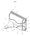
- Fig. 2 is a perspective view showing the appearance of the color CRT apparatus 1.
- the color CRT apparatus 1 includes: a glass bulb 5 that includes a face panel 2, a funnel 3 connected to the back of the face panel 2, and a neck 4 connected to the back of the funnel 3; an electron gun 11 embedded in the neck 4; and a deflection yoke 6 that is attached to the funnel 3 to surround the end portion of the funnel 3 near the neck 4.
- a metal tensile band 7 is attached to the rim of the face panel 2 to prevent the glass bulb 5 from imploding.
- An ear 71 is attached to each of the four corners of the tensile band 7. The ears 71 are used for attaching the CRT apparatus 1 to the body of a television apparatus.
- a pair of degaussing coils 8 and 9 are wound around the upper portion and the lower portion of the glass bulb 5, respectively, to be substantially symmetric, as shown in Fig. 2.
- Each of the degaussing coils 8 and 9 is made by winding a conductive wire a plurality of turns to make a coil and covering the surface of the coil with, for example, insulation tape.
- the degaussing coils 8 and 9 are hooked around the ears 71 of the tensile band 7 and are positioned on the glass bulb 5.
- An inner magnetic shield 15 (see Fig. 3) and the like are degaussed when an attenuation alternating current is fed through the degaussing coils 8 and 9 so as to generate an attenuation alternating magnetic field between the degaussing coils 8 and 9.
- a loop coil 10 is also wound around the glass bulb 5, between a color-selection electrode 13 (see Fig. 3) and the deflection yoke 6.
- the loop coil 10 is made in a manner similar to that of the degaussing coils 8 and 9 by winding a conductive wire a plurality of turns to make a coil and covering the surface of the coil with, for example, insulation tape.
- the loop coil 10 is fixed to the degaussing coils 8 and 9 by tape 111 or the like at the intersections thereof and is thereby positioned on the glass bulb 5.
- the loop coil 10 is adhered to the bottom of the face panel 2 at the center thereof by adhesive tape 112 so as to prevent the loop coil 10 from hanging down and the loop shape from deforming.
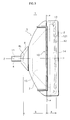
- Fig. 3 is a top plan view of the CRT apparatus 1 shown in Fig. 2. It should be noted here that for the purpose of simply explaining the arrangement of the loop coil 10, the degaussing coils 8 and 9 and the tensile band 7 are omitted from Fig. 3.
- a horizontally extending portion of the loop coil 10 lies in a plane ⁇ (hereinafter referred to as "coil position reference plane ⁇ ") that is perpendicular to the tube axial Z.
- the left-hand-side and the right-hand-side portions of the loop coil 10 are bent toward the deflection yoke 6 at an angle of approximately 90 degrees, to be substantially symmetric, as shown in Fig. 3.
- Red, green, and blue phosphors are applied to an inner surface 12 of the face panel 2 to form a phosphor screen 121.
- the color-selection electrode 13, which is, for example, a shadow mask, is disposed inside the face panel 2.
- the reference number 14 represents a frame that supports the color-selection electrode 13 by tension.
- the reference number 15 represents the inner magnetic shield that prevents the terrestrial magnetism from entering inside and prevents a component of the terrestrial magnetism perpendicular to the tube axial from adversely affecting the trajectory of the electron beams.
- the mark “a” represents a distance, along the tube axial, between (i) an intersection of the inner surface of the face panel 2 and the tube axial and (ii) the coil position reference plane ⁇ in which long, horizontally extending portions of the loop coil 10 lie.
- the mark “b” represents a distance, along the tube axial, between the coil position reference plane ⁇ and a reference line RL of the glass bulb 5.
- the present invention fully exerts the advantageous effects when the value "b/a" is set to an appropriate range.
- Fig. 4A shows the shape of the loop coil 10 for detailed explanation thereof.
- the loop coil 10 is formed by bending the two sides (the left-hand-side and the right-hand-side portions) of an approximately rectangular coil toward the deflection yoke 6 (upward, in Fig. 4A) so as to have two bent portions that look like steps.
- the loop coil 10 is positioned in the CRT apparatus 1 so that the long sides of the original rectangle lie in the coil position reference plane ⁇ , a plane perpendicular to the tube axial Z, and the short sides of the original rectangle in the bent portions are distant from the coil position reference plane ⁇ .
- the loop coil 10 has two bent portions 101 which are formed by bending an approximately rectangular coil toward the deflection yoke 6 at substantially the same positions on the long sides to be symmetrical.
- the loop coil 10 having been formed as described above, includes long sides 10a and 10b that are positioned to include the coil position reference plane ⁇ .
- the loop coil 10 also includes the two bent portions 101 which contain short sides 10c and 10d of the original rectangle, respectively.
- the long sides 10a and 10b correspond to the first coil unit, and the bent portions 101 correspond to the second coil unit.
- the amount of landing deviation correction is reduced at the bent portions 101, compared with the corresponding short sides in the conventional rectangular coil.
- the long sides 10a and 10b are placed near the frit seal, where the face panel 2 is joined with the funnel 3 so that if a small amount of current is fed through the long sides 10a and 10b, a large amount of landing deviation is corrected there, and the short sides 10c and 10d are distanced from the frit seal so that a small amount of landing deviation is corrected at the bent portions 101.
- the landing deviation can be corrected over the whole screen neither too much nor too little when the tilt of the image is corrected.
- the loop coil 10 shaped as shown in Fig. 4 is particularly effective when the color-selection electrode 13 is a mask(hereinafter referred to as "iron SST mask") that is formed by spanning tensed thin plates made of iron. The reason is as follows.
- the iron SST mask is made so that each central area of the upper and lower portions has higher tension than the four corners of the screen, not to be affected by the vibration of the speaker or the like.
- the iron since the iron has a negative magneto-striction coefficient, the central areas of the upper and lower portions with higher tension have lower magnetic property than the four corners.
- the iron SST mask is, as a magnetic shield, less effective at the central areas of the upper and lower portions where the terrestrial magnetism is more apt to enter the CRT along the tube axial, increasing the amount of landing deviation.
- Fig. 4A represents the horizontal length of the horizontally extending portions of the loop coil 10, namely the long sides 10a and 10b.
- Fig. 4B is a perspective view of an effective screen 21 of the CRT apparatus 1.
- the mark "W” in Fig. 4B represents the horizontal length of the effective screen 21.
- an effective screen is defined as “an area in which images are displayed, the area being a part of the face panel”
- a comparative example was also prepared.
- the comparative example is a color CRT apparatus having a loop coil placed to surround the glass bulb near the frit seal (see Fig. 1). Otherwise, the comparative example is identical with the color CRT apparatus of the present embodiment.
- Figs. 5A-5C show measurement results of the amount of electron beam landing deviation ( ⁇ m) and the image tilt in the case where the loop coil 10 in the present embodiment was used.
- Figs. 5D-5F show measurement results of the amount of electron beam landing deviation ( ⁇ m) and the image tilt in the case where the loop coil of the comparative example was used.
- the terrestrial magnetism along the tube axial was 50 ⁇ T.
- the comparative experiment was conducted as follows.
- a degaussing process is performed in the environment where no magnetic field exists. That is to say, magnetic substances in the glass bulb, such as the color-selection electrode, the frame, and the inner magnetic shield, are degaussed by feeding an attenuation alternating current through the degaussing coils for a certain time period.
- Figs. 5A and 5D show the reference values, respectively.
- the deflection yoke was fixed so that no image tilt occurs. As a result, no image tilt occurred.
- Figs. 5B and 5E show the measurement results. Both images displayed on the screen were tilting under the influence of the terrestrial magnetism.
- the landing deviation can be corrected over the whole screen neither too much nor too little when the tilt of the screen is corrected, and high-quality images with less color drift can be obtained, compared with the case where a conventional loop coil is used.
- the sensitivity of the tilt correction and the amount of landing deviation correction vary depending on the distance "a” (a distance between (i) an intersection of the inner surface of the face panel 2 and the tube axial and (ii) the coil position reference plane ⁇ : see Fig. 3) , but more precisely, depending on a relative relationship between the distance "a” and a distance between the deflection center and the loop coil 10.
- the distance between the deflection center and the loop coil 10 can be represented as the distance "b" (a distance, along the tube axial, between the coil position reference plane ⁇ and the reference line RL).
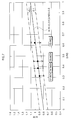
- Fig. 6 shows the results of the experiment.
- the horizontal axis represents the screen size
- the vertical axis represents the values of the ratio b/a.
- the optimal range of the values of the ratio b/a is, therefore, from 1.6 to 10, inclusive.
- the amount of landing deviation measured at the fields N and S is in a range from -10 ⁇ m to +10 ⁇ m in each CRT apparatus of any size.
- the width of the stripe of the phosphor of each color in the phosphor screen in a color CRT apparatus having the highest definition currently is 0.55 mm.
- the amount of landing deviation is no larger than 20 ⁇ m, no color drift is observed.
- a very advantageous effect is provided when the amount of landing deviation measured at the fields N and S is in a range from -10 ⁇ m to +10 ⁇ m.
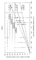
- the length A should also be determined in relative relation to the size of the CRT apparatus, in particular, in relative relation to the length W (horizontal length of the effective screen). This is because the present invention aims to solve the problem of the imbalance in the amount of landing deviation correction between the fields N and S and the four corners of the screen, and the imbalance varies depending on the relative relationship between the length W and the length A, in other words, the positions at which the bent portions 101 are formed.
- the horizontal axis represents the values of D/NS, and the vertical axis represents the values of A/W.
- the ranges indicated by the vertical arrows for the different sizes are ranges of the values L in which the correction of landing deviation at the four corners is improved. That is to say, if a value L is larger than the range, the bent portions do not function in correcting the landing deviations at the four corners. On the contrary, if a value L is smaller than the range, the loop coil of the present embodiment loses its merits over the conventional loop coil and corrects the landing deviations at the four corners excessively.
- Fig. 9 shows results of comparative experiments conducted to show the advantageous effects of the CRT apparatus 1 in the present embodiment.
- the CRT apparatuses of the present invention showed excellent results, with the values of landing deviation being within the range from -10 ⁇ m to +10 ⁇ m at both the fields N and S and the four corners.
- conditional expressions (1), (4), and (5) were obtained from the experiments which were conducted on CRT apparatuses of typical sizes, namely 29-inch, 32-inch, 34-inch, and 36-inch types, it was confirmed through the experiments that CRT apparatuses of other sizes also improve the amount of landing deviation at the fields N and S and the four corners in so far as they meet the conditional expressions (1), (4), and (5), at least in comparison with the case where the conventional loop coil is used.
- Fig. 10 is a block diagram showing the circuit construction of a television receiver 200, an example of an image display apparatus, to which the color CRT apparatus 1 is applied.
- the television receiver 200 includes an image signal reception circuit 202, an audio circuit 203, a color signal reproduction circuit 204, a synchronization circuit 205, a speaker 206, a vertical deflection circuit 207, a horizontal deflection circuit 208, an image tilt adjustment unit 210, and the color CRT apparatus 1.
- the image signal reception circuit 202 receives a television signal via an antenna 201, detects and separates the television signal into an audio signal, an image signal, and a synchronization signal, and sends the signals to the audio circuit 203, the color signal reproduction circuit 204, and the synchronization circuit 205, respectively.
- the audio circuit 203 drives the speaker 206 and reproduces the sounds in accordance with the received audio signal.
- the color signal reproduction circuit 204 demodulates color signals of red (R), green (G), and blue (B) in accordance with the received image signal, and causes the in-line electron gun 11 of the color CRT apparatus 1 to emit three electron beams of R, G, and B by applying voltages to the electron gun 11 in correspondence with the color signals of R, G, and B, respectively.
- the synchronization circuit 205 separates the synchronization signal into a vertical synchronization signal and a horizontal synchronization signal, and outputs the signals to the vertical deflection circuit 207 and the horizontal deflection circuit 208, respectively.
- the vertical deflection circuit 207 and the horizontal deflection circuit 208 generate sawtooth currents in accordance with the input synchronization signals, and supply the sawtooth currents to a vertical deflection coil and a horizontal deflection coil (both not illustrated) in the deflection yoke 6 as a vertical deflection current and a horizontal deflection current, respectively. This allows the electron beams of each color to be deflected regularly, and the phosphor screen 121 (see Fig. 3) to be raster-scanned.
- the image tilt adjustment unit 210 adjusts the image tilt and the amount of landing deviation in accordance with a user input.
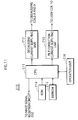
- Fig. 11 is a block diagram showing the construction of the image tilt adjustment unit 210.
- the image tilt adjustment unit 210 includes a CPU 211, a degaussing current supplying unit 212, a tilt correction current supplying unit 213, a ROM 214, an EEPROM 215, and an operation unit 216.
- the degaussing current supplying unit 212 supplies an attenuation alternating current to the degaussing coils 8 and 9 for a certain time period in accordance with an instruction by the CPU 211.
- the tilt correction current supplying unit 213 adjusts the image tilt by varying the intensity and the direction of the current fed through the loop coil 10, in accordance with a user input received via the operation unit 216.
- the ROM 214 stores a control program for the tilt adjustment and image data of a horizontal pattern.
- the EEPROM 215 holds a value of the current fed through the loop coil 10, the current value being the final one having been determined through the tilt adjustment.
- Fig. 12 shows an example of input buttons provided in the operation unit 216.
- the image tilt adjustment unit 210 When the user presses down an image tilt adjustment button 217, the image tilt adjustment unit 210 is switched to a tilt adjustment mode. While the image tilt adjustment unit 210 is in the tilt adjustment mode, the user can corrects the image tilt by operating a rotation button 218 or 219, and press down an OK button 220 for establishing the correction.
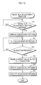
- Fig. 13 is a flowchart showing the procedure of the image tilt adjustment process executed by the image tilt adjustment unit 210.
- step S1 it is judged whether the image tilt adjustment button 217 was pressed down. If it is judged affirmatively in step S1 the control moves to step S2 in which the image data of a horizontal pattern is read from the ROM 214, the read image data is sent to the image signal reception circuit 202, and a horizontal pattern 22 is displayed on the screen as shown in Fig. 14.
- the image tilt adjustment unit 210 determines the amount and direction of the current supplied to the loop coil 10, in accordance with the amount of rotation of the rotation button 218 or 219 made by the user attempting to make the horizontal pattern 22 be displayed horizontally on the screen, and sends the determined amount and direction of the current to the tilt correction current supplying unit 213. This process (tilt adjustment reception process) is continued until the OK button 220 is pressed down (steps S3 and S4).
- step S4 When it is judged in step S4 that the OK button 220 was pressed down, the image tilt adjustment unit 210 judges that the tilt adjustment by the user has completed, and stores a value of the current being fed through the loop coil 10 into the EEPROM 215 together with the direction of the current (step S5), and thereafter performs the image tilt correction by feeding the current of the stored value through the loop coil 10 in the stored direction.
- step S6 the horizontal pattern is deleted. With this operation, the screen is returned to the state before the image tilt adjustment process. While the screen is in this state, the degaussing process is executed (step S7).
- the degaussing current supplying unit 212 feeds an attenuation alternating current through the degaussing coils 8 and 9, allowing an attenuation alternating magnetic field to be generated between the degaussing coils 8 and 9 and degaussing the magnetic substances in the glass bulb, such as the inner magnetic shield 15 and the color-selection electrode 13.
- the magnetic substances in the glass bulb 5 are degaussed even if they have been affected by the magnetic field generated by the loop coil 10. This improves the magnetic shield effect, and reduces the landing deviation.
- the color CRT apparatus of the present invention can be varied as follows, for example.
- the loop coil 10 is formed by bending an approximately rectangular loop coil.
- the loop coil 10 may be formed by bending, for example, a circular or oval loop coil. It is preferable that the loop coil 10 is attached to the glass bulb 5 so as to lie along the surface thereof since there is a fear that the loop coil 10 may be deformed by some accidental contact during an assembly process or the like.
- the loop coil 10 has the bent portions 101 that are bent as described in the embodiment and the attached drawings.
- the shape of the bent portions 101 may be different from the one shown in the embodiment in so far as part of the loop coil 10 projects toward the deflection yoke, achieving the purpose of correcting the landing deviation appropriately.
- the pair of bent portions 101 may not be symmetrical and the loop coil 10 may have only one bent portion, depending on how electron beams land.
- the loop coil 10 is fixed to the degaussing coils 8 and 9 by tape 111 or the like at the intersections thereof and is thereby positioned on the glass bulb 5. This prevents the loop coil 10 from being separated from the glass bulb 5 and falling down.
- the loop coil 10 may be fixed to the degaussing coils 8 and 9 by other methods.
- a coil unit may be formed in advance by fixing the loop coil 10 to the degaussing coils 8 and 9, then the coil unit may be attached to the glass bulb 5 during the manufacturing of the color CRT apparatus 1. This provides a smooth work at the production line.
- the loop coil 10 is adhered to the bottom of the face panel 2 by adhesive tape 112 so as to prevent the loop coil 10 from hanging down and the loop shape from deforming.
- the loop coil 10 may be fixed to the degaussing coil 9 at a certain position in the lower portion of the loop coil 10 when the coil unit is formed. This saves time and trouble for adhering the adhesive tape 112 on the production line.
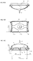
- Figs. 15A, 15B, and 15C show the first example of the above-described fixing method, and Figs. 16A, 16B, and 16C the second example.
- Figs. 15A and 16A, Figs. 15B and 16B, and Figs. 15C and 16C are top plan views, back views, and bottom views of a CRT to which the loop coil 10 and the degaussing coils 8 and 9 have been attached, respectively.
- the marks " ⁇ ” indicate positions at which the loop coil 10 is fixed to the degaussing coils 8 and 9 in advance by tape or the like
- the marks "X” indicate the corners of the tensile band 7 at which the degaussing coils 8 and 9 are hooked around the ears 71.
- the dimensions are provided in these figures as an example, for the case where the CRT apparatus is of a 36-inch type and the aspect ratio of the screen is 16:9.
- the loop coil 10 is bent toward the degaussing coil 9 at approximately the center of the lower horizontal portion of the loop coil 10, and the loop coil 10 and the degaussing coil 9 are fixed to each other at the bend (reference number "113" in Fig. 15C).
- the loop coil 10 is bent toward the degaussing coil 9 at three positions (reference numbers "114", “115", and "116" in Fig. 16C) of the lower horizontal portion of the loop coil 10, and the loop coil 10 and the degaussing coil 9 are fixed to each other at the three bends.
- a coil unit with the above-described construction may be formed in advance, and then by hooking the degaussing coils 8 and 9 around the ears 71 of the tensile band 7 on the production line of the color CRT apparatus 1, attachment and positioning of the loop coil 10 and the degaussing coils 8 and 9 are done at the same time. This improves the productivity of the color CRT apparatus 1.
Landscapes
- Physics & Mathematics (AREA)
- Electromagnetism (AREA)
- Video Image Reproduction Devices For Color Tv Systems (AREA)
- Vessels, Lead-In Wires, Accessory Apparatuses For Cathode-Ray Tubes (AREA)
Applications Claiming Priority (2)
| Application Number | Priority Date | Filing Date | Title |
|---|---|---|---|
| JP2002138171 | 2002-05-14 | ||
| JP2002138171 | 2002-05-14 |
Publications (2)
| Publication Number | Publication Date |
|---|---|
| EP1363310A2 true EP1363310A2 (de) | 2003-11-19 |
| EP1363310A3 EP1363310A3 (de) | 2006-05-03 |
Family
ID=29267766
Family Applications (1)
| Application Number | Title | Priority Date | Filing Date |
|---|---|---|---|
| EP03252995A Withdrawn EP1363310A3 (de) | 2002-05-14 | 2003-05-14 | Kathodenstrahlröhre, Vorrichtung mit Kathodenstrahlröhre, Bildanzeigegerät und Spuleneinheit |
Country Status (4)
| Country | Link |
|---|---|
| US (1) | US6963181B2 (de) |
| EP (1) | EP1363310A3 (de) |
| KR (1) | KR20030088377A (de) |
| CN (1) | CN1476042A (de) |
Families Citing this family (1)
| Publication number | Priority date | Publication date | Assignee | Title |
|---|---|---|---|---|
| US7981023B2 (en) * | 2005-07-25 | 2011-07-19 | Boston Scientific Scimed, Inc. | Elastic sling system and related methods |
Family Cites Families (6)
| Publication number | Priority date | Publication date | Assignee | Title |
|---|---|---|---|---|
| US2921226A (en) * | 1956-05-24 | 1960-01-12 | Philco Corp | Apparatus for color purity correction in color television receivers |
| US4950955A (en) * | 1988-09-06 | 1990-08-21 | Rca Licensing Corporation | Magnetic field compensator for a CRT |
| US4963789A (en) * | 1989-05-01 | 1990-10-16 | Conrac Scd, Inc. | Method and apparatus for dynamic magnetic field neutralization |
| US5066891A (en) * | 1990-01-02 | 1991-11-19 | Raytheon Company | Magnetic field cancellation circuit |
| JP3744250B2 (ja) * | 1999-03-31 | 2006-02-08 | 松下電器産業株式会社 | 陰極線管装置 |
| JP2002199412A (ja) * | 2000-12-27 | 2002-07-12 | Toshiba Corp | 消磁コイル装置及び消磁コイルを有するブラウン管装置 |
-
2003
- 2003-05-13 US US10/437,210 patent/US6963181B2/en not_active Expired - Fee Related
- 2003-05-14 CN CNA031787002A patent/CN1476042A/zh active Pending
- 2003-05-14 EP EP03252995A patent/EP1363310A3/de not_active Withdrawn
- 2003-05-14 KR KR10-2003-0030429A patent/KR20030088377A/ko not_active Ceased
Also Published As
| Publication number | Publication date |
|---|---|
| CN1476042A (zh) | 2004-02-18 |
| EP1363310A3 (de) | 2006-05-03 |
| KR20030088377A (ko) | 2003-11-19 |
| US6963181B2 (en) | 2005-11-08 |
| US20040004427A1 (en) | 2004-01-08 |
Similar Documents
| Publication | Publication Date | Title |
|---|---|---|
| JP2001256897A (ja) | カラー陰極線管 | |
| US6963181B2 (en) | Cathode-ray tube, cathode-ray tube apparatus, image display apparatus, and coil unit | |
| US6664724B2 (en) | Shadow mask for color CRT | |
| JP2004031305A (ja) | 陰極線管 | |
| JP4061243B2 (ja) | 陰極線管、陰極線管装置、画像表示装置およびコイルユニット | |
| EP0997924B1 (de) | Farb-Kathodenstrahlröhre mit Vorrichtung zur Korrektur der Kreuzkonvergenz | |
| EP0793253B1 (de) | Korrektur des negativ differentiellen Komafehlers in Kathodenstrahlröhren | |
| EP0882306B1 (de) | Farbkathodenstrahlröhre und deren herstellungsverfahren | |
| JPH05252525A (ja) | 偏向ヨーク装置 | |
| EP0310242B1 (de) | Farbanzeigesystem mit selbstkonvergierendem Ablenkjoch mit Rasterverzerrungskorrektur | |
| JP3381615B2 (ja) | カラー陰極線管 | |
| EP1206792A1 (de) | Anzeigevorrichtung mit einer ablenkeinheit | |
| US6407518B2 (en) | Moire-reduced color display device including a color cathode ray tube | |
| KR100414484B1 (ko) | 평면 브라운관의 프레임 구조 | |
| EP1622183B1 (de) | Spule zur Modulation der Abtastgeschwindigkeit und Kathodenstrahlröhre | |
| US6278348B1 (en) | Deflection yoke | |
| JPH0963512A (ja) | 偏向ヨーク及びコンバージェンス修正方法 | |
| JP2001202908A (ja) | カラー受像管装置 | |
| US20040183426A1 (en) | Deflection coil for deflection yoke | |
| US20030107334A1 (en) | Deflection yoke with multiple pairs of vertical coils and switched deflection current | |
| JPH10241602A (ja) | ビーム補正用マグネット及びこれを用いたカラー表示装置 | |
| JPH1140076A (ja) | 陰極線管装置 | |
| JPH09306385A (ja) | 偏向装置 | |
| KR20040006520A (ko) | 음극선관용 편향 요크 | |
| JP2002042693A (ja) | カラー陰極線管 |
Legal Events
| Date | Code | Title | Description |
|---|---|---|---|
| PUAI | Public reference made under article 153(3) epc to a published international application that has entered the european phase |
Free format text: ORIGINAL CODE: 0009012 |
|
| AK | Designated contracting states |
Kind code of ref document: A2 Designated state(s): AT BE BG CH CY CZ DE DK EE ES FI FR GB GR HU IE IT LI LU MC NL PT RO SE SI SK TR |
|
| AX | Request for extension of the european patent |
Extension state: AL LT LV MK |
|
| PUAL | Search report despatched |
Free format text: ORIGINAL CODE: 0009013 |
|
| AK | Designated contracting states |
Kind code of ref document: A3 Designated state(s): AT BE BG CH CY CZ DE DK EE ES FI FR GB GR HU IE IT LI LU MC NL PT RO SE SI SK TR |
|
| AX | Request for extension of the european patent |
Extension state: AL LT LV MK |
|
| 17P | Request for examination filed |
Effective date: 20060904 |
|
| 17Q | First examination report despatched |
Effective date: 20061016 |
|
| AKX | Designation fees paid |
Designated state(s): DE FR GB |
|
| GRAP | Despatch of communication of intention to grant a patent |
Free format text: ORIGINAL CODE: EPIDOSNIGR1 |
|
| STAA | Information on the status of an ep patent application or granted ep patent |
Free format text: STATUS: THE APPLICATION IS DEEMED TO BE WITHDRAWN |
|
| 18D | Application deemed to be withdrawn |
Effective date: 20080411 |