EP1363151B1 - Support individuel de lentille optique - Google Patents
Support individuel de lentille optique Download PDFInfo
- Publication number
- EP1363151B1 EP1363151B1 EP03291111A EP03291111A EP1363151B1 EP 1363151 B1 EP1363151 B1 EP 1363151B1 EP 03291111 A EP03291111 A EP 03291111A EP 03291111 A EP03291111 A EP 03291111A EP 1363151 B1 EP1363151 B1 EP 1363151B1
- Authority
- EP
- European Patent Office
- Prior art keywords
- base
- carrier according
- spring
- lens
- support
- Prior art date
- Legal status (The legal status is an assumption and is not a legal conclusion. Google has not performed a legal analysis and makes no representation as to the accuracy of the status listed.)
- Expired - Lifetime
Links
- 230000003287 optical effect Effects 0.000 title claims description 8
- 239000000463 material Substances 0.000 claims description 34
- 238000000465 moulding Methods 0.000 claims description 16
- 230000000903 blocking effect Effects 0.000 claims description 11
- 238000013519 translation Methods 0.000 claims description 9
- 238000010438 heat treatment Methods 0.000 claims description 8
- 230000007935 neutral effect Effects 0.000 claims description 7
- 230000000295 complement effect Effects 0.000 claims description 4
- OVSKIKFHRZPJSS-UHFFFAOYSA-N 2,4-D Chemical compound OC(=O)COC1=CC=C(Cl)C=C1Cl OVSKIKFHRZPJSS-UHFFFAOYSA-N 0.000 claims description 2
- 229930182556 Polyacetal Natural products 0.000 claims description 2
- 230000009471 action Effects 0.000 claims description 2
- 230000001154 acute effect Effects 0.000 claims description 2
- 230000009477 glass transition Effects 0.000 claims description 2
- 229920006324 polyoxymethylene Polymers 0.000 claims description 2
- 229920001577 copolymer Polymers 0.000 claims 1
- 239000011347 resin Substances 0.000 claims 1
- 229920005989 resin Polymers 0.000 claims 1
- 238000011282 treatment Methods 0.000 description 41
- 239000011521 glass Substances 0.000 description 17
- 238000005119 centrifugation Methods 0.000 description 15
- 238000000151 deposition Methods 0.000 description 8
- 238000012423 maintenance Methods 0.000 description 8
- 238000012545 processing Methods 0.000 description 7
- 230000008021 deposition Effects 0.000 description 6
- 238000004519 manufacturing process Methods 0.000 description 6
- 235000012431 wafers Nutrition 0.000 description 5
- 230000006978 adaptation Effects 0.000 description 4
- 238000004140 cleaning Methods 0.000 description 4
- 239000011248 coating agent Substances 0.000 description 4
- 238000000576 coating method Methods 0.000 description 4
- 239000000470 constituent Substances 0.000 description 4
- 239000010410 layer Substances 0.000 description 4
- 238000000034 method Methods 0.000 description 4
- 239000000758 substrate Substances 0.000 description 4
- 238000004381 surface treatment Methods 0.000 description 4
- 230000008901 benefit Effects 0.000 description 3
- 238000009826 distribution Methods 0.000 description 3
- 238000004064 recycling Methods 0.000 description 3
- 240000008042 Zea mays Species 0.000 description 2
- 238000005452 bending Methods 0.000 description 2
- 230000008859 change Effects 0.000 description 2
- 239000011247 coating layer Substances 0.000 description 2
- 230000001010 compromised effect Effects 0.000 description 2
- 230000006866 deterioration Effects 0.000 description 2
- 230000000694 effects Effects 0.000 description 2
- 238000005516 engineering process Methods 0.000 description 2
- 230000007717 exclusion Effects 0.000 description 2
- 238000009434 installation Methods 0.000 description 2
- 230000014759 maintenance of location Effects 0.000 description 2
- 238000012544 monitoring process Methods 0.000 description 2
- 230000036961 partial effect Effects 0.000 description 2
- 230000035515 penetration Effects 0.000 description 2
- 230000002829 reductive effect Effects 0.000 description 2
- 230000000284 resting effect Effects 0.000 description 2
- 238000007665 sagging Methods 0.000 description 2
- 238000003860 storage Methods 0.000 description 2
- 239000000126 substance Substances 0.000 description 2
- 241001644893 Entandrophragma utile Species 0.000 description 1
- XUIMIQQOPSSXEZ-UHFFFAOYSA-N Silicon Chemical compound [Si] XUIMIQQOPSSXEZ-UHFFFAOYSA-N 0.000 description 1
- 238000005299 abrasion Methods 0.000 description 1
- 230000003667 anti-reflective effect Effects 0.000 description 1
- 238000012550 audit Methods 0.000 description 1
- 238000007664 blowing Methods 0.000 description 1
- 229920006026 co-polymeric resin Polymers 0.000 description 1
- 239000002131 composite material Substances 0.000 description 1
- 238000013461 design Methods 0.000 description 1
- 238000006073 displacement reaction Methods 0.000 description 1
- 229940082150 encore Drugs 0.000 description 1
- 230000000977 initiatory effect Effects 0.000 description 1
- 229910052500 inorganic mineral Inorganic materials 0.000 description 1
- 230000000670 limiting effect Effects 0.000 description 1
- 238000003754 machining Methods 0.000 description 1
- 238000004377 microelectronic Methods 0.000 description 1
- 239000011707 mineral Substances 0.000 description 1
- 244000045947 parasite Species 0.000 description 1
- 230000003071 parasitic effect Effects 0.000 description 1
- 230000002093 peripheral effect Effects 0.000 description 1
- 238000004321 preservation Methods 0.000 description 1
- 230000008569 process Effects 0.000 description 1
- 230000001681 protective effect Effects 0.000 description 1
- 230000009467 reduction Effects 0.000 description 1
- 230000035939 shock Effects 0.000 description 1
- 229910052710 silicon Inorganic materials 0.000 description 1
- 239000010703 silicon Substances 0.000 description 1
- 239000007787 solid Substances 0.000 description 1
- 241000894007 species Species 0.000 description 1
- 238000004528 spin coating Methods 0.000 description 1
- 238000003892 spreading Methods 0.000 description 1
- 230000007480 spreading Effects 0.000 description 1
- 229920002994 synthetic fiber Polymers 0.000 description 1
- 238000012360 testing method Methods 0.000 description 1
- 230000007704 transition Effects 0.000 description 1
- 238000009966 trimming Methods 0.000 description 1
- 239000002966 varnish Substances 0.000 description 1
Images


Classifications
-
- G—PHYSICS
- G02—OPTICS
- G02B—OPTICAL ELEMENTS, SYSTEMS OR APPARATUS
- G02B7/00—Mountings, adjusting means, or light-tight connections, for optical elements
- G02B7/02—Mountings, adjusting means, or light-tight connections, for optical elements for lenses
-
- B—PERFORMING OPERATIONS; TRANSPORTING
- B29—WORKING OF PLASTICS; WORKING OF SUBSTANCES IN A PLASTIC STATE IN GENERAL
- B29D—PRODUCING PARTICULAR ARTICLES FROM PLASTICS OR FROM SUBSTANCES IN A PLASTIC STATE
- B29D11/00—Producing optical elements, e.g. lenses or prisms
- B29D11/00009—Production of simple or compound lenses
- B29D11/00432—Auxiliary operations, e.g. machines for filling the moulds
-
- B—PERFORMING OPERATIONS; TRANSPORTING
- B29—WORKING OF PLASTICS; WORKING OF SUBSTANCES IN A PLASTIC STATE IN GENERAL
- B29D—PRODUCING PARTICULAR ARTICLES FROM PLASTICS OR FROM SUBSTANCES IN A PLASTIC STATE
- B29D11/00—Producing optical elements, e.g. lenses or prisms
- B29D11/00865—Applying coatings; tinting; colouring
Definitions
- the present invention generally relates to the surface treatment of optical lenses and, more particularly, although not exclusively, to corrective or protective ophthalmic lenses. It relates more specifically to the support of such lenses during their treatment.
- ophthalmic lens in the context of the present invention and conventionally, a molded and / or machined puck made of mineral or synthetic material which has a convex front face and a concave rear face and from which is then derived, by clipping, a glass of glasses to mount on a mount.
- the edge of this lens most often affects a generally cylindrical shape, circular or oval. But it is not systematically so, so that in the context of the present invention, the edge of the lens to be treated should be considered as any.
- ophthalmic lenses it is customary to apply to the ophthalmic lenses, after forming them by molding or machining, one or more surface treatments for imparting particular otic or mechanical characteristics such as abrasion resistance or anti-reflective properties.
- the application of such a treatment to an ophthalmic lens most often involves the deposition of at least one layer of coating material on one of its faces. Often also the lens is heated to high relative temperatures of up to 140 ° C.
- the individual support comprises a ring-shaped base with a circular contour, the outer face of which bears the fastening means on the collective support and, borne by this base, three holding studs. the lens by its slice.
- One of these pads is fixed relative to the base (while being optionally adjustable in position), while the other two pads are connected to the base via a curved spring blade reported by its middle on the inner face of the base and carrying at its two free ends the two pads.
- the latter are thus provided with a radial mobility specific to the seizure of the lens by its edge with a slight elastic clamping.
- centrifugation treatment to an ophthalmic lens allows the deposition of all types of layers, thin or thick, with good thickness regularity and at relatively high rates.
- an individual lens holder serving as an interface for fixing the lens on a turntable.
- it is important to ensure the reliability of the attachment of the lens which implies firstly that the maintenance of the lens on its individual support is sufficiently precise and solid, and any case resistant to centrifugal forces, and secondly that the individual support itself has a seat and / or sufficient support on the turntable.
- DE-38 38 012 describes an individual support comprising three clamping elements each of which consists of a support finger which receives the lens and a clamping finger which grips the latter.
- a feeder device makes it possible to vary the pressure exerted on the lens as a function of the speed of rotation. This results in a particularly complex and therefore unreliable and expensive, both in manufacturing and operation.
- This support for ophthalmic lens comprises a flat base disc-shaped or crown and carried by this base, three studs holding the lens by its edge. Two of these pads are fixed relative to the base, while the third pad is movable radially, between an inner position of rest and a range of active external positions.
- a spring is arranged between the movable stud and the base to exert an elastic return force of the movable stud towards its rest position, thus conferring on the mobile stud a radial elasticity proper to the gripping of the lens by its edge with an elastic clamping .
- the spring is made in the form of an elastically flexible blade whose two ends are reported by means of mounting terminals on the upper face of the base and the middle of which carries the movable stud.
- the term "embedding" is improper: in fact, the spring blade is simply stopped rotating on each terminal, but retains its sliding mobility in its longitudinal direction, otherwise the radial displacement of the movable stud would be extremely reduced, if not zero. As a result, the spring blade is, in this context, necessarily separated from the terminals and the base.
- the support comprises an axial locking means for holding the mobile stud, at least when it is in the active position, in a fixed axial position while leaving its radial mobility, and the assembly of said support , with the base, the pads, the spring and the axial locking means, is made in one piece integrally made of plastic material directly molded.
- the monoblock support thus obtained is compact and easy to handle (by hand or directly by an automated machine element) without risk of disassembly of its constituent parts and with very little risk of deterioration in case of accidental fall or shock.
- the support thus obtained can be adapted to any type of treatment, in particular by centrifugation or under vacuum, and will have for this purpose a base suitably arranged for its attachment to the corresponding type of machine.
- an axial locking means of the movable stud is provided to maintain, at least when in the active position, the movable stud in a fixed axial position, for example in the plane median, while leaving it radial mobility. It is important to ensure that the movable stud is sufficiently rigid in the axial direction, that is to say perpendicularly to the plane of the base, the only support exerted by the spring being insufficient in this respect. .
- the axial locking means prevents the risk of axial deformation of the spring and the movable pin (ie the risk of vertical sagging in the case of a centrifugation treatment where the lens and its support are placed at horizontally) which would cause a change in the attitude of the lens, or even the breaking of its maintenance by the mobile pin, to the detriment of the quality and the smooth course of treatment.
- This is of particular importance when, as is most often the treatment applied to the lens involves a heating phase at relatively high temperatures likely to cause softening of the material constituting the support and in particular the pads and the spring that the connects to the base.
- the blocking means is made in one piece molded with the rest of the support and comprises two mutually-engaged radial parts, one movable integral with the movable stud and the other secured to the mobile terminal. base, arranged to be disengaged from each other in the rest position of the movable stud and to engage with each other in the active position.
- the disengagement configuration of the two parts of the locking means in the rest position has the great advantage of allowing the molding in a single operation, without insert, of the entire support with the two parts of the locking means.
- the axial locking means furthermore exerts a radial guide, its two parts being complementary to produce, when mutually engaged, a radial slide connection.
- the slide link thus formed opposes advantageously any inadvertent tilting of the movable stud on itself, not only around an axis parallel to the central axis of the base by excessive bending of the spring, but also around an orthoradial axis by torsion of the spring.
- a support of this type for the surface treatment of a lens, in which the disposable support is dedicated to the treatment of a single lens and is abandoned. after the treatment of this lens.
- Such a single-use implementation of the support is made possible because of its constitution and its method of production in a single piece, which induce low manufacturing costs and allow easy recycling. It is also understood that this unique use is advantageous in terms of logistics, mainly in that it simplifies the manipulations (manual or automated support) and, above all, avoids any step of cleaning the support, in favor of simplicity and the fluidity of the treatment cycles and, consequently, a lower operating cost.
- the base advantageously carries an individual identification mark of the glass allowing individual monitoring of the glass mounted on the support.
- the studs are arranged such that, whatever the position of the movable stud on a 6 mm outward stroke from its position resting, the edge of the lens, circular, is, relative to the central axis of the base, offset to the two fixed studs.
- the glass does not exert any pressure. centrifugal force on the mobile block with elastic return, but the centrifugal force exerted on the glass tends instead to press the latter in support against the fixed studs.
- the base has a flattened shape, having an axial dimension (that is to say a thickness) very substantially less than its radial dimension (that is to say, its width).
- This dimensional characteristic offers a double interest for the use of the support in a centrifugal lens treatment.
- a sufficient seating surface is obtained to allow the fixing of the support by one of the two faces of the base on the turntable of a centrifugation treatment apparatus equipped with a pneumatic suction device, that is to say having a plurality of suction orifices distributed over a circumference of the plate to maintain the base against the plate by suction of its bearing face.
- the axial dimension, that is to say the thickness, of the base is as small as possible, while remaining Rigid enough for reliability and accuracy of maintenance.
- the spring comprises at least one filament of material, the strand of which neutral extends in a plane parallel to the median plane of the base.
- the plane of the neutral strand of the filament of matter merges with the median plane of the base, which then advantageously forms a joint plane.
- the spring can advantageously be made in the form of two filaments of material, symmetrical to one another with respect to a plane of symmetry containing the central axis of the base and the direction of translation of the movable stud. .
- Each filament then preferably has at least one non-rectilinear part, curved or broken.
- This part may for example be corrugated, which makes it possible to satisfy both the molding constraints and the search for a regular elasticity over a wide range.
- the two parts of the locking means are connected to one another by at least one thread of low strength material, c that is to say, capable of being broken by the exercise of a radial manual effort provoking the mutual engagement of the two parties.
- the two parts of the blocking means are thus held properly wedged opposite one another, without any offset likely to impair their radial mutual engagement.
- a sufficient radial force exerted on the movable pin causes the rupture of the mesh of material and, jointly, the mutual engagement of the two parts.
- the material constituting the support is chosen and the spring is arranged so that, for an ambient temperature of between 15 ° C. and 140 ° C., with at least 10 flash heating cycles. 20 seconds at 140 ° C, the modulus of elasticity of the spring is between 3 N / mm and 10 N / mm. It is indeed important that the radial clamping force exerted by the spring on the edge of the lens, while remaining sufficient for a reliable maintenance of the lens even at high speeds of rotation, is not too high, so as not to risk to distort, if only locally, the lens during a heat treatment causing a relative softening of the lens.
- the treatment temperatures can indeed reach 140 ° C.
- the material constituting the support has a glass transition temperature greater than or equal to 150 ° C.
- each pad having a bearing face facing the axis of the base, at least one of the pads has at least one notch on its bearing face.
- the stud in question may have on its support face at least two nesting notches.
- the or each notch is centered on the plane of the base.
- the or each notch preferably has a depth of less than 0.5 mm and advantageously greater than 0, 2 mm so that it retains some efficiency.
- an individual optical lens support according to the invention comprises an annular base 1, generally of revolution about a central axis 100 and having a median plane perpendicular to this central axis.
- the support is more specifically intended for use for a centrifugation treatment whose machines require, for the fixation of the lens support on their turntable (not shown), a seat of relatively large radial dimension while no particular axial dimension is required.
- a centrifugation treatment indeed involves a rotation of the support at high speeds, greater than 500 revolutions per minute.
- the axial dimension, that is to say the thickness, of the base 1 is as small as possible, while remaining sufficiently rigid for reliability and accuracy of maintenance. Indeed, during deposition by centrifugation, the surplus material is ejected from the lens in the form of droplets at a speed that increases as the speed of rotation is high.
- the annular support is too thick, its inner edge forms a kind of peripheral enclosure wall surrounding the lens and hindering the free evacuation of the droplets, the latter bouncing against the inner edge of the support to fall back on the lens. The quality of the treatment, particularly as to the regularity of the deposit, is affected.
- the base may have any generally annular shape (washer, ring, ring, etc.) of any section and will be suitably arranged for fixing on the type of corresponding machine. It can thus, in particular, affect a general shape of a ring having a height greater than its thickness which is more suitable for use in a vacuum processing machine where the fixing of the lens support is effected by the external face of the ring.
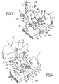
- the support For holding the lens by its edge, the support is provided with three studs 2, 3 and 4 formed projecting from the inner edge 5 of the base 1. These three studs are regularly distributed around the axis 100, thus forming between them two by two at an angle of 120 degrees.
- the pads 2 and 3 are fixed relative to the base 1 and are connected to the inner edge 5 thereof by projections 40, 41 of the inner edge.
- the stud 4 is elastically mobile in translation, radially with respect to the axis 100, that is to say in the direction of a ray 101 passing through the center of the mobile stud 4.
- a spring is arranged between the mobile stud 4 and the base 1 for exerting an elastic return force of the movable stud 4 towards a rest position illustrated by FIG. 1.
- This return spring is made in the form of two filaments of material 6, 7 whose neutral strand (ie the central line) extends in the median plane of the base 1.
- the two filaments spring 6, 7 are moreover symmetrical to each other with respect to a plane of symmetry containing the central axis 100 of the base 1 and the direction 101 of translation of the movable stud 4. In the present case, these two filaments 6, 7 have a slightly smaller thickness than the base 1.
- Each of the two filaments 6, 7 consists of two parts: a substantially rectilinear part 8, 9 and a non-rectilinear part 10, 11.
- the rectilinear portion 8, 9 is connected to the inner edge 5 of the base 1 and forms with the plane of symmetry, on the inner side of the base, an acute angle ⁇ , which is in this case 70 degrees to 20% near.
- the non-rectilinear portion 10, 11 of the filament is adjacent to the movable stud 4. It may be curved or broken and has the function of conferring on the mobile stud 4 a radial elastic mobility range sufficient to allow convenient placement of the lens and possibly an adaptation to different lens diameters.
- this non-rectilinear part 10, 11 is curved and more precisely corrugated, which makes it possible to satisfy both the molding constraints and the search for a regular elasticity over a wide range. More specifically, the corrugated portion 10, 11 of the filament consists of a single fold.
- the movable stud 4 is thus movable between an internal rest position illustrated by FIGS. 1, 2, 3 and 5 and a range of active external positions starting at 1 mm from the rest position and covering the different lens diameters envisaged.
- Figures 4 and 6 illustrate one of these active positions.
- the pads are arranged to hold lenses having an edge diameter of between 68 and 73 mm, which corresponds to a range of active external positions of 5 mm.
- the determining element is the mobile terminal 4 whose mobile and elastic connection to the base 1 gives it by nature a less good rigidity than that fixed studs 2 and 3.
- an axial locking means of the movable stud 4 is provided to maintain, when in the active position, the mobile stud 4 in a fixed axial position, that is to say in this case centered on the plane of the base 1, while leaving it radial mobility.
- the axial locking means prevents the risk of axial deformation of the spring 6, 7 and the movable stud 4 (that is to say the risk of vertical collapse for the case of a centrifugation treatment where the lens and its support are placed horizontally) which would cause a change in the attitude of the lens, or even the breaking of its maintenance by the mobile pin 4, to the detriment of the quality and smooth processing.
- This is of particular importance when, as is most often the treatment applied to the lens involves a heating phase at relatively high temperatures, up to 140 ° C likely to cause a softening of the material constituent of the support and in particular of the mobile pads 4 and the spring filaments 6, 7 which connect it to the base 1.
- the locking means comprises two mutually radially engaging parts, with a movable portion 12 integral with the movable stud 4 and a fixed part 13 integral with the base 1. More specifically, the fixed part 13 forms a slide axis 101 arranged to slidingly receive the movable portion 12 which thus forms a drawer.
- the slide 12 and the slide 13 are symmetrical with respect to the plane of symmetry formed by the axes 100 and 101.
- FIGS. 3 to 6 Reference is now made for a better readability of the drawings in FIGS. 3 to 6.
- the drawer 12 is in the general shape of a wafer. It has an upper face 14 and a lower face 15. These faces 14 and 15 are described as superior and inferior by mere distinctive convenience and with reference to FIGS. 1 to 4, without this constituting any limitation, since the support can be used on either side and can be returned with the lens it wears for double-sided treatment thereof.
- the slide 12 furthermore has a free cylindrical outer edge 16 with an axis 100, an inner edge 17 carrying the movable stud 4 and to which the corrugated portion 10, 11 of each of the filaments 6, 7 and two lateral edges 18, 19 are connected. parallel to the axis 101.
- a notch 20 is formed in recess of the outer edge 16 and the upper face 14 of the drawer 12. This notch thus has a bottom 21 which is parallel to the outer edge 16 and which forms a recess.
- two grooves 22, 23 parallel to the axis 101 are formed recessing the side edges 18, 19 and the lower face 15, symmetrically on either side of the plane of symmetry formed by the axes 100 and 101.
- the slideway 13 is formed in the body of the base 1, in recess of its inner edge 5. It comprises a recess 24 for receiving the slide 12 and, bordering and delimiting this recess parallel to the axis 101, three rails 25 , 27, 28.
- the rail 25 is centered on the plane of symmetry formed by the axes 100 and 101 and is flush with the upper face of the base 1. It has, along the axis 100, a height less than that of the base 1 and equal to that of the notch 20, so that when the movable stud 4 is pushed into the active position, the rail 25 fits into the notch 20 and forms an axial stop, along the axis 100, for the drawer 14.
- the rail 25 also has a free inner edge 26 against which the bottom 21 of the notch 20 abuts to limit the stroke of the movable stud 4. This stroke limitation avoids the deterioration of the spring filaments 6, 7 by excessive deformation. We have seen previously that in the proposed example this stroke from the rest position is limited to about 6 mm.
- the rails 27, 28 are formed symmetrically on either side of the plane of symmetry formed by the axes 100 and 101 and are flush with the lower face of the base 1.
- Each of the rails 27, 28 has, along the axis 100, a height less than that of the base 1 and equal to that of the grooves 22, 23, so that when the movable stud 4 is pushed into the active position, the rails 27, 28 are embedded in the grooves 22, 23.
- the rails 27, 28 thus form an axial abutment, along the axis 100, for the slide 14 which is complementary to that formed by the rail 25 in the other direction.
- the slide 12 and therefore the movable pin 4 are immobilized in a certain position along the axis 100 (ie in this case vertically), in both directions (ie upwards and downwards), which allows the reversal of the support for a double-sided treatment of the lens.
- the drawer 12 and the mobile block 4 of course retain their radial mobility, along the axis 101.
- the rails 27, 28 are each provided with a chamfered free inner end 29, 30, in this case in the shape of a point, which s' extends internally beyond the inner edge 26 of the rail 25 to ensure, if necessary, a resetting on the axis 101 of the slide 12 before the penetration of the rail 25 in the notch 20.
- the drawer 12 In the rest position of the mobile stud 14, the drawer 12 is disengaged from the slide 13. However, in this rest position, the drawer 12 is opposite the slide 13 and its outer edge 16 is flush with the entry thereof. , so that as soon as the drawer 12 is pushed outwards, and in any case after a stroke of 1 mm, in the active position, it enters the slideway 13.
- the sliding link thus formed opposes advantageously to any inadvertent tilting of the movable stud on itself, not only around an axis parallel to the central axis of the base by excessive bending of the spring, but also around an orthoradial axis by torsion of the spring.
- the slide 12 and the slideway 13 are connected to one another by two thin threads of material 31, 32.
- the species these threads are formed between the tip of the ends 29, 30 of the rails 27, 28 and the mouth of the grooves 22, 23 on the outer edge 16 of the drawer 15.
- This net has a low mechanical strength, possibly with a point of initiation of rupture, which means that it is capable of being broken by the exercise of a manual radial force causing the engagement of the slide 12 in the slide 13.
- a sufficient radial force exerted on the movable stud 4 causes the breaking of the material thread and, together, the engagement of the slide 12 in the slide 13. And this commitment will not be compromised by the possible exercise of a force comprising, in addition to its component main radial, an axial or orthoradial component parasite, the mesh of material opposing any shift of the drawer until the engagement is not initiated.
- the thread of material also constitutes a witness of integrity of the support, its break betraying an earlier use or damage during storage or transport.
- Each stud has a bearing face 35 facing the central axis 100.
- This bearing face is provided with one or more notches for receiving the edge of the lens 50, as shown in FIG. 6, to secure the axial retention (ie along the axis 100) of the lens by the studs 2, 3, 4, while avoiding excessive tightening for the reasons mentioned above.
- each stud has on its support surface two nesting notches 36, 37 of different heights, the smallest being formed in the bottom of the largest 36.
- the large notch 36 and the small notch 37 have, along the axis 100 of the base 1, the respective heights of 4 and 2 mm to 20%.
- the small notch 37 of 2 mm then receives the lenses of thickness between 0 and 2 mm, while the large notch 36 of 4 mm receives the lenses of thickness between 2 and 4 mm.
- the lenses having a thickness on a slice greater than or equal to the height of the larger of the two notches that is to say in the example taken above a greater thickness or equal to 4 mm
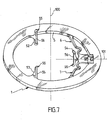
- use another support also identical to that previously described, comprising in accordance with Figure 7, pads 52, 53, 54 similar respectively to the pads 2, 3, 4 of Figures 1 to 6, but each having on their bearing surface 55 a single large notch 56 extending over more than two thirds of the total height of the stud.
- the notch 55 has a height along the central axis 100 of 13 mm to 20%, each stud having a height of 16 mm to 20%.
- the notch (s) 36, 37, 56 are centered on the median plane of the base 1. This gives a symmetrical distribution of forces, which makes it possible in particular to prevent any tilting or deflection of the pads and in particular of the mobile pad 4.
- the studs 2, 3, 4 are arranged such that, whatever the position of the mobile stud 4 on its stroke 6 mm outwards from its rest position, the circular edge of a lens mounted on the support either, with respect to the axis of rotation of the support which is in this case the central axis 100 of the base, is oriented or offset to the two fixed studs 2, 3.
- the glass does not exert a centrifugal force on the movable pin 4 with elastic return.
- the centrifugal force exerted on the glass tends instead to press the latter in support against the fixed studs 2, 3.
- the or each notch 36, 37, 56 preferably has a depth less than 0.5 mm and advantageously greater than 0.2 mm so that it retains some efficiency.
- the or each notch 36, 37, 56 has a depth of 0.3 mm to 10%.
- the inner and outer slices of the base 1, the filaments 6, 7 and the studs 2, 3, 4 are blunted. to avoid as much as possible to oppose walls perpendicular to the trajectory of varnish drops ejected from the glasses, especially in the case of a centrifugation treatment.
- the entire support, with its base 1, its pads 2, 3, 4, the spring 6, 7 and the locking and guiding means 12, 13, is made in one piece integrally made of plastic material coming directly from molding .
- the molding is carried out with two half-molds joined in a joint plane coinciding with the median plane of the base 1.
- the material constituting the support has a transition temperature. vitreous greater than or equal to 150 ° C.
- the two parts, drawer 12 and slide 13, the blocking and guiding means are made in one piece molded with the rest of the support.
- the disengagement configuration of the slide 12 vis-à-vis the slide 13 in the rest position allows their molding in one operation with the entire support.
- the support which has just been described is, according to the invention, intended to be used for the surface treatment of a lens, in particular by centrifugation.
- the optical lens 50 is simply inserted, by its edge 51, between the two fixed studs 2, 3 and the mobile stud 4. The latter has previously been radially biased towards the outside, against the restoring force exerted by the spring filaments 6, 7.
- the movable stud 4 is then released and, under the action of the spring filaments 6, 7, retracts against the wafer 51 of the lens 50.
- the lens 50 is thus held tight by its wafer 51 between the mobile pad 4 and the pads fixed 2, 3.
- the support carrying the lens is then attached to or in the appropriate element of the processing machine used (not shown).
- the base 1 serves as an interface with this machine element and is accordingly arranged as to its shape, its dimensions and possible specific arrangements (groove, shoulder, etc.).
- the base can take the particular form previously described and illustrated by the figures, namely a general form of washer having two bearing faces (“upper” and “Lower”) wide offering a good seating on the platen of the centrifuge machine.
- the lens is also accessible by its two faces.
- the monoblock support obtained directly from molding is particularly suitable for use in the single-use type. It is then dedicated to the treatment of a single lens and is abandoned after the treatment of this lens on one or both sides.
- Such a single-use implementation of the support is made possible because of its constitution and its method of production in a single piece, which induce low manufacturing costs and allow easy recycling. It is also understood that this unique use is advantageous in terms of logistics, mainly in that it simplifies handling (manual or automated support) and, above all, avoids any step of cleaning the support, in favor of the security of the environment and people (vis-à-vis the cleaning chemicals), as well as the simplicity and fluidity of the treatment cycles and therefore a lower cost.
- the base then advantageously carries an individual identification mark of the glass, coming from molding.
- This mark can for example be in the form of a bar code. It is thus possible to use this identification mark, associated with each particular glass and, consequently, the treatments it must undergo, to ensure the monitoring of glass, both in terms of logistics and as regards the treatment process. It is thus possible in particular to individualize the different processing operations to be applied to each glass within a multi-process installation. It is also possible, thanks to the individual marking, to direct each glass to the stations dedicated to the processing operations required for the glass in question. This referral can be done within a single treatment site or between several off-site sites.
Landscapes
- Engineering & Computer Science (AREA)
- Physics & Mathematics (AREA)
- Health & Medical Sciences (AREA)
- Manufacturing & Machinery (AREA)
- Ophthalmology & Optometry (AREA)
- Mechanical Engineering (AREA)
- General Physics & Mathematics (AREA)
- Optics & Photonics (AREA)
- Eyeglasses (AREA)
- Lens Barrels (AREA)
- Optical Couplings Of Light Guides (AREA)
- Prostheses (AREA)
- Window Of Vehicle (AREA)
- Grinding And Polishing Of Tertiary Curved Surfaces And Surfaces With Complex Shapes (AREA)
Applications Claiming Priority (2)
| Application Number | Priority Date | Filing Date | Title |
|---|---|---|---|
| FR0205930A FR2839788B1 (fr) | 2002-05-14 | 2002-05-14 | Support individuel de lentille optique |
| FR0205930 | 2002-05-14 |
Publications (2)
| Publication Number | Publication Date |
|---|---|
| EP1363151A1 EP1363151A1 (fr) | 2003-11-19 |
| EP1363151B1 true EP1363151B1 (fr) | 2006-06-28 |
Family
ID=29266103
Family Applications (1)
| Application Number | Title | Priority Date | Filing Date |
|---|---|---|---|
| EP03291111A Expired - Lifetime EP1363151B1 (fr) | 2002-05-14 | 2003-05-12 | Support individuel de lentille optique |
Country Status (7)
Families Citing this family (19)
| Publication number | Priority date | Publication date | Assignee | Title |
|---|---|---|---|---|
| JP2004347814A (ja) * | 2003-05-21 | 2004-12-09 | Canon Inc | 保持装置、露光装置及びデバイス製造方法 |
| EP1914579A1 (en) | 2006-10-18 | 2008-04-23 | ESSILOR INTERNATIONAL Compagnie Générale d'Optique | Optical lens holder for holding lenses during manufacturing process |
| US8146902B2 (en) * | 2006-12-21 | 2012-04-03 | Lam Research Corporation | Hybrid composite wafer carrier for wet clean equipment |
| FI121742B (fi) * | 2007-07-04 | 2011-03-31 | Theta Optics Ltd Oy | Menetelmä optisen tuotteen valmistamiseksi ja laitteisto |
| DE102007063305A1 (de) * | 2007-12-27 | 2009-07-02 | Carl Zeiss Smt Ag | Optische Einrichtung mit einer Federeinrichtung mit einem Bereich konstanter Federkraft |
| DE202008004018U1 (de) | 2008-03-20 | 2008-05-21 | Oculus Optikgeräte GmbH | Positioniervorrichtung für ein optisches Element |
| DE102008022211B3 (de) * | 2008-05-06 | 2010-02-25 | Carl Zeiss Surgical Gmbh | Linsenträger sowie optische Baugruppe |
| CN102471870A (zh) * | 2009-07-30 | 2012-05-23 | Hoya株式会社 | 光学镜片用气相沉积装置 |
| USD636420S1 (en) * | 2010-05-06 | 2011-04-19 | Kuo-Chin Huang | Concentrator lens |
| FR2959831B1 (fr) * | 2010-05-10 | 2013-02-15 | Essilor Int | Procede de preparation d'une lentille ophtalmique equipee d'une marque memoire. |
| CN102565980B (zh) * | 2010-12-30 | 2015-06-17 | 上海微电子装备有限公司 | 一种光学元件固定装置及其安装方法 |
| US9784939B2 (en) * | 2014-02-03 | 2017-10-10 | Robert S. Hodge | Optical retaining device |
| TWM521747U (zh) * | 2015-10-16 | 2016-05-11 | 大立光電股份有限公司 | 遮光片、遮光元件、光學元件、成像鏡頭與鏡頭模組 |
| TWI582482B (zh) * | 2015-11-20 | 2017-05-11 | 晶睿通訊股份有限公司 | 鏡頭固定機構及其影像擷取裝置 |
| US20180239102A1 (en) * | 2017-02-20 | 2018-08-23 | Corning Incorporated | Optical mount |
| JP6660508B1 (ja) * | 2019-06-24 | 2020-03-11 | 株式会社アサヒビジョン | レンズ保持装置及びレンズ光学特性測定装置 |
| DE102020003578A1 (de) * | 2020-05-20 | 2021-11-25 | Schneider Gmbh & Co. Kg | Beschichtungsanlage, Spannring und Magazin für Brillengläser und Verfahren zum Beschichten von Brillengläsern |
| EP4122688A1 (en) * | 2021-07-19 | 2023-01-25 | Essilor International | Optical article holding device |
| CN115421271B (zh) * | 2022-10-01 | 2025-05-23 | 昆明理工大学 | 一种透镜柔性支撑结构 |
Family Cites Families (12)
| Publication number | Priority date | Publication date | Assignee | Title |
|---|---|---|---|---|
| FR799770A (fr) | 1935-12-21 | 1936-06-19 | Chantier & Ateliers De Saint N | Dispositif pour amortir les percussions provoquées par une hélice sur le bordé d'un navire |
| GB538324A (en) * | 1939-07-25 | 1941-07-29 | Kodak Ltd | Improvements in or relating to the mounting of lenses |
| US2532971A (en) * | 1947-04-12 | 1950-12-05 | Pacific Universal Products Cor | Method and apparatus for producing optical coatings |
| DE3838012A1 (de) * | 1988-11-09 | 1990-05-10 | Fraunhofer Ges Forschung | Werkstuecktraeger |
| US5249082A (en) * | 1991-05-08 | 1993-09-28 | Eastman Kodak Company | Exact constraint arrangement for and methods of mounting an element such as a lens |
| FR2746769B1 (fr) | 1996-04-02 | 1998-06-12 | Smurfit Socar Sa | Conteneur gerbable en un materiau semi-rigide, flan pour la realisation de ce conteneur et procede de fabrication de ce flan |
| GB2318191B (en) * | 1996-10-14 | 2001-10-03 | Asahi Seimitsu Kk | Mount shift apparatus of lens for cctv camera |
| US5751501A (en) * | 1996-11-16 | 1998-05-12 | Spot Technology, Inc. | Lens mounting structure of a scanner |
| JP3754810B2 (ja) * | 1997-09-19 | 2006-03-15 | キヤノン株式会社 | 補正光学系支持装置 |
| FR2783055B1 (fr) * | 1998-09-04 | 2000-11-24 | Essilor Int | Support pour lentille optique, et son procede de mise en oeuvre |
| US6469844B1 (en) * | 1999-06-02 | 2002-10-22 | Fuji Photo Film Co., Ltd. | Lens holding method and lens holder |
| DE10053899A1 (de) * | 2000-10-31 | 2002-05-08 | Zeiss Carl | Vorrichtung zur Lagerung eines optischen Elementes |
-
2002
- 2002-05-14 FR FR0205930A patent/FR2839788B1/fr not_active Expired - Fee Related
-
2003
- 2003-05-12 ES ES03291111T patent/ES2266749T3/es not_active Expired - Lifetime
- 2003-05-12 AT AT03291111T patent/ATE331970T1/de not_active IP Right Cessation
- 2003-05-12 EP EP03291111A patent/EP1363151B1/fr not_active Expired - Lifetime
- 2003-05-12 DE DE60306451T patent/DE60306451T2/de not_active Expired - Lifetime
- 2003-05-14 JP JP2003136384A patent/JP4215560B2/ja not_active Expired - Fee Related
- 2003-05-14 US US10/437,841 patent/US6842299B2/en not_active Expired - Lifetime
Also Published As
| Publication number | Publication date |
|---|---|
| DE60306451T2 (de) | 2007-02-08 |
| FR2839788B1 (fr) | 2004-11-05 |
| US6842299B2 (en) | 2005-01-11 |
| FR2839788A1 (fr) | 2003-11-21 |
| JP4215560B2 (ja) | 2009-01-28 |
| EP1363151A1 (fr) | 2003-11-19 |
| JP2004133379A (ja) | 2004-04-30 |
| US20040036989A1 (en) | 2004-02-26 |
| ATE331970T1 (de) | 2006-07-15 |
| DE60306451D1 (de) | 2006-08-10 |
| ES2266749T3 (es) | 2007-03-01 |
Similar Documents
| Publication | Publication Date | Title |
|---|---|---|
| EP1363151B1 (fr) | Support individuel de lentille optique | |
| EP1109946B1 (fr) | Support pour lentille optique, et son procede de mise en oeuvre | |
| EP1480805B1 (fr) | Projecteur de phare de vehicule automobile comprenant une lentille en verre et un support de lentille en matiere plastique et procede de realisation d'un tel projecteur par surmoulage du support sur la lentille | |
| CA2607030C (fr) | Outil de surfacage d'une surface optique | |
| FR2907699A1 (fr) | Patin de polissage ayant des rainures espacees de maniere irreguliere | |
| EP1699592B1 (fr) | Support de blocage pneumatique d'une lentille optique | |
| WO2018121948A1 (fr) | Module d'alimentation d'un dispositif de transfert ou de transport, notamment de comprimes pharmaceutiques | |
| FR2801825A1 (fr) | Dispositif destine a maintenir un tampon abrasif sur un polissoir dans un appareil de fabrication de lentilles pour verres oculaires | |
| CA2531960C (fr) | Outil pour le surfacage d'une surface optique | |
| FR2935628A1 (fr) | Outil de surfacage a qualite optique | |
| FR2625533A1 (fr) | Lanceur de demarreur | |
| EP0974422B1 (fr) | Outil de finissage, notamment pour lentille ophtalmique, et équipements propres à sa mise en oeuvre | |
| CA2304217A1 (fr) | Dispositif d'essorage pour tete de balai | |
| EP1801627A2 (fr) | Ensemble comportant une lentille optique et un support, ainsi que procede les mettant en oeuvre | |
| EP1703993B1 (fr) | Procede de traitement par trempage d'elements optiques | |
| EP1974887A1 (fr) | Base tournante transformable associée à des moules d'injection de matières plastiques | |
| EP3182229B1 (fr) | Mécanisme de chronographe à rattrapante à isolateur | |
| EP2509744B1 (fr) | Outil de surfacage a qualite optique | |
| FR2514378A1 (fr) | Disque de friction pour un dispositif de fausse torsion a friction pour fils synthetiques | |
| EP3226080B1 (fr) | Système de barillet pour pièce d'horlogerie | |
| EP3560396B1 (fr) | Dispositif de fixation d'un feutre d'essuyage et ensemble qui le comporte | |
| FR2671738A1 (fr) | Support individuel retournable pour application d'un traitement a un quelconque substrat, en particulier un verre de lunettes, et materiel propre a la mise en óoeuvre d'un tel support. | |
| CH705907A2 (fr) | Palier antichoc de pièce d'horlogerie en polymère. | |
| FR3144764A1 (fr) | Système de retrait d’étiquettes adhésives de contenants, machine de traitement de contenants et procédé de retrait d’étiquettes associés | |
| FR2629275A1 (fr) | Piece de maintien mecanique pour circuits hyperfrequences |
Legal Events
| Date | Code | Title | Description |
|---|---|---|---|
| PUAI | Public reference made under article 153(3) epc to a published international application that has entered the european phase |
Free format text: ORIGINAL CODE: 0009012 |
|
| AK | Designated contracting states |
Kind code of ref document: A1 Designated state(s): AT BE BG CH CY CZ DE DK EE ES FI FR GB GR HU IE IT LI LU MC NL PT RO SE SI SK TR |
|
| AX | Request for extension of the european patent |
Extension state: AL LT LV MK |
|
| 17P | Request for examination filed |
Effective date: 20031016 |
|
| AKX | Designation fees paid |
Designated state(s): AT BE BG CH CY CZ DE DK EE ES FI FR GB GR HU IE IT LI LU MC NL PT RO SE SI SK TR |
|
| 17Q | First examination report despatched |
Effective date: 20050324 |
|
| GRAP | Despatch of communication of intention to grant a patent |
Free format text: ORIGINAL CODE: EPIDOSNIGR1 |
|
| GRAS | Grant fee paid |
Free format text: ORIGINAL CODE: EPIDOSNIGR3 |
|
| GRAA | (expected) grant |
Free format text: ORIGINAL CODE: 0009210 |
|
| AK | Designated contracting states |
Kind code of ref document: B1 Designated state(s): AT BE BG CH CY CZ DE DK EE ES FI FR GB GR HU IE IT LI LU MC NL PT RO SE SI SK TR |
|
| PG25 | Lapsed in a contracting state [announced via postgrant information from national office to epo] |
Ref country code: IT Free format text: LAPSE BECAUSE OF FAILURE TO SUBMIT A TRANSLATION OF THE DESCRIPTION OR TO PAY THE FEE WITHIN THE PRESCRIBED TIME-LIMIT;WARNING: LAPSES OF ITALIAN PATENTS WITH EFFECTIVE DATE BEFORE 2007 MAY HAVE OCCURRED AT ANY TIME BEFORE 2007. THE CORRECT EFFECTIVE DATE MAY BE DIFFERENT FROM THE ONE RECORDED. Effective date: 20060628 Ref country code: RO Free format text: LAPSE BECAUSE OF FAILURE TO SUBMIT A TRANSLATION OF THE DESCRIPTION OR TO PAY THE FEE WITHIN THE PRESCRIBED TIME-LIMIT Effective date: 20060628 Ref country code: IE Free format text: LAPSE BECAUSE OF FAILURE TO SUBMIT A TRANSLATION OF THE DESCRIPTION OR TO PAY THE FEE WITHIN THE PRESCRIBED TIME-LIMIT Effective date: 20060628 Ref country code: SK Free format text: LAPSE BECAUSE OF FAILURE TO SUBMIT A TRANSLATION OF THE DESCRIPTION OR TO PAY THE FEE WITHIN THE PRESCRIBED TIME-LIMIT Effective date: 20060628 Ref country code: NL Free format text: LAPSE BECAUSE OF FAILURE TO SUBMIT A TRANSLATION OF THE DESCRIPTION OR TO PAY THE FEE WITHIN THE PRESCRIBED TIME-LIMIT Effective date: 20060628 Ref country code: AT Free format text: LAPSE BECAUSE OF FAILURE TO SUBMIT A TRANSLATION OF THE DESCRIPTION OR TO PAY THE FEE WITHIN THE PRESCRIBED TIME-LIMIT Effective date: 20060628 Ref country code: SI Free format text: LAPSE BECAUSE OF FAILURE TO SUBMIT A TRANSLATION OF THE DESCRIPTION OR TO PAY THE FEE WITHIN THE PRESCRIBED TIME-LIMIT Effective date: 20060628 Ref country code: FI Free format text: LAPSE BECAUSE OF FAILURE TO SUBMIT A TRANSLATION OF THE DESCRIPTION OR TO PAY THE FEE WITHIN THE PRESCRIBED TIME-LIMIT Effective date: 20060628 Ref country code: CZ Free format text: LAPSE BECAUSE OF FAILURE TO SUBMIT A TRANSLATION OF THE DESCRIPTION OR TO PAY THE FEE WITHIN THE PRESCRIBED TIME-LIMIT Effective date: 20060628 |
|
| REG | Reference to a national code |
Ref country code: GB Ref legal event code: FG4D Free format text: NOT ENGLISH |
|
| REG | Reference to a national code |
Ref country code: CH Ref legal event code: EP |
|
| GBT | Gb: translation of ep patent filed (gb section 77(6)(a)/1977) |
Effective date: 20060719 |
|
| REG | Reference to a national code |
Ref country code: IE Ref legal event code: FG4D Free format text: LANGUAGE OF EP DOCUMENT: FRENCH |
|
| REF | Corresponds to: |
Ref document number: 60306451 Country of ref document: DE Date of ref document: 20060810 Kind code of ref document: P |
|
| PG25 | Lapsed in a contracting state [announced via postgrant information from national office to epo] |
Ref country code: SE Free format text: LAPSE BECAUSE OF FAILURE TO SUBMIT A TRANSLATION OF THE DESCRIPTION OR TO PAY THE FEE WITHIN THE PRESCRIBED TIME-LIMIT Effective date: 20060928 Ref country code: DK Free format text: LAPSE BECAUSE OF FAILURE TO SUBMIT A TRANSLATION OF THE DESCRIPTION OR TO PAY THE FEE WITHIN THE PRESCRIBED TIME-LIMIT Effective date: 20060928 |
|
| PG25 | Lapsed in a contracting state [announced via postgrant information from national office to epo] |
Ref country code: PT Free format text: LAPSE BECAUSE OF FAILURE TO SUBMIT A TRANSLATION OF THE DESCRIPTION OR TO PAY THE FEE WITHIN THE PRESCRIBED TIME-LIMIT Effective date: 20061128 |
|
| NLV1 | Nl: lapsed or annulled due to failure to fulfill the requirements of art. 29p and 29m of the patents act | ||
| REG | Reference to a national code |
Ref country code: IE Ref legal event code: FD4D |
|
| REG | Reference to a national code |
Ref country code: ES Ref legal event code: FG2A Ref document number: 2266749 Country of ref document: ES Kind code of ref document: T3 |
|
| PLBE | No opposition filed within time limit |
Free format text: ORIGINAL CODE: 0009261 |
|
| STAA | Information on the status of an ep patent application or granted ep patent |
Free format text: STATUS: NO OPPOSITION FILED WITHIN TIME LIMIT |
|
| 26N | No opposition filed |
Effective date: 20070329 |
|
| BERE | Be: lapsed |
Owner name: ESSILOR INTERNATIONAL (COMPAGNIE GENERALE D'OPTIQ Effective date: 20070531 |
|
| REG | Reference to a national code |
Ref country code: CH Ref legal event code: PL |
|
| PG25 | Lapsed in a contracting state [announced via postgrant information from national office to epo] |
Ref country code: MC Free format text: LAPSE BECAUSE OF NON-PAYMENT OF DUE FEES Effective date: 20070531 |
|
| PG25 | Lapsed in a contracting state [announced via postgrant information from national office to epo] |
Ref country code: LI Free format text: LAPSE BECAUSE OF NON-PAYMENT OF DUE FEES Effective date: 20070531 Ref country code: CH Free format text: LAPSE BECAUSE OF NON-PAYMENT OF DUE FEES Effective date: 20070531 |
|
| PG25 | Lapsed in a contracting state [announced via postgrant information from national office to epo] |
Ref country code: BE Free format text: LAPSE BECAUSE OF NON-PAYMENT OF DUE FEES Effective date: 20070531 |
|
| PG25 | Lapsed in a contracting state [announced via postgrant information from national office to epo] |
Ref country code: GR Free format text: LAPSE BECAUSE OF FAILURE TO SUBMIT A TRANSLATION OF THE DESCRIPTION OR TO PAY THE FEE WITHIN THE PRESCRIBED TIME-LIMIT Effective date: 20060929 |
|
| PG25 | Lapsed in a contracting state [announced via postgrant information from national office to epo] |
Ref country code: BG Free format text: LAPSE BECAUSE OF FAILURE TO SUBMIT A TRANSLATION OF THE DESCRIPTION OR TO PAY THE FEE WITHIN THE PRESCRIBED TIME-LIMIT Effective date: 20060928 |
|
| PG25 | Lapsed in a contracting state [announced via postgrant information from national office to epo] |
Ref country code: EE Free format text: LAPSE BECAUSE OF FAILURE TO SUBMIT A TRANSLATION OF THE DESCRIPTION OR TO PAY THE FEE WITHIN THE PRESCRIBED TIME-LIMIT Effective date: 20060628 |
|
| PG25 | Lapsed in a contracting state [announced via postgrant information from national office to epo] |
Ref country code: CY Free format text: LAPSE BECAUSE OF FAILURE TO SUBMIT A TRANSLATION OF THE DESCRIPTION OR TO PAY THE FEE WITHIN THE PRESCRIBED TIME-LIMIT Effective date: 20060628 Ref country code: LU Free format text: LAPSE BECAUSE OF NON-PAYMENT OF DUE FEES Effective date: 20070512 |
|
| PG25 | Lapsed in a contracting state [announced via postgrant information from national office to epo] |
Ref country code: HU Free format text: LAPSE BECAUSE OF FAILURE TO SUBMIT A TRANSLATION OF THE DESCRIPTION OR TO PAY THE FEE WITHIN THE PRESCRIBED TIME-LIMIT Effective date: 20061229 Ref country code: TR Free format text: LAPSE BECAUSE OF FAILURE TO SUBMIT A TRANSLATION OF THE DESCRIPTION OR TO PAY THE FEE WITHIN THE PRESCRIBED TIME-LIMIT Effective date: 20060628 |
|
| PGFP | Annual fee paid to national office [announced via postgrant information from national office to epo] |
Ref country code: ES Payment date: 20100419 Year of fee payment: 8 |
|
| PGFP | Annual fee paid to national office [announced via postgrant information from national office to epo] |
Ref country code: DE Payment date: 20100727 Year of fee payment: 8 Ref country code: GB Payment date: 20100420 Year of fee payment: 8 |
|
| GBPC | Gb: european patent ceased through non-payment of renewal fee |
Effective date: 20110512 |
|
| REG | Reference to a national code |
Ref country code: DE Ref legal event code: R119 Ref document number: 60306451 Country of ref document: DE Effective date: 20111201 |
|
| PG25 | Lapsed in a contracting state [announced via postgrant information from national office to epo] |
Ref country code: GB Free format text: LAPSE BECAUSE OF NON-PAYMENT OF DUE FEES Effective date: 20110512 |
|
| REG | Reference to a national code |
Ref country code: ES Ref legal event code: FD2A Effective date: 20130606 |
|
| PG25 | Lapsed in a contracting state [announced via postgrant information from national office to epo] |
Ref country code: DE Free format text: LAPSE BECAUSE OF NON-PAYMENT OF DUE FEES Effective date: 20111201 |
|
| PG25 | Lapsed in a contracting state [announced via postgrant information from national office to epo] |
Ref country code: ES Free format text: LAPSE BECAUSE OF NON-PAYMENT OF DUE FEES Effective date: 20110513 |
|
| REG | Reference to a national code |
Ref country code: FR Ref legal event code: PLFP Year of fee payment: 14 |
|
| REG | Reference to a national code |
Ref country code: FR Ref legal event code: PLFP Year of fee payment: 15 |
|
| REG | Reference to a national code |
Ref country code: FR Ref legal event code: PLFP Year of fee payment: 16 |
|
| REG | Reference to a national code |
Ref country code: FR Ref legal event code: TP Owner name: ESSILOR INTERNATIONAL, FR Effective date: 20180601 |
|
| PGFP | Annual fee paid to national office [announced via postgrant information from national office to epo] |
Ref country code: FR Payment date: 20200525 Year of fee payment: 18 |
|
| PG25 | Lapsed in a contracting state [announced via postgrant information from national office to epo] |
Ref country code: FR Free format text: LAPSE BECAUSE OF NON-PAYMENT OF DUE FEES Effective date: 20210531 |