EP1362948B1 - Procédé pour la déshydratation d' une bande fibreuse - Google Patents
Procédé pour la déshydratation d' une bande fibreuse Download PDFInfo
- Publication number
- EP1362948B1 EP1362948B1 EP03016713A EP03016713A EP1362948B1 EP 1362948 B1 EP1362948 B1 EP 1362948B1 EP 03016713 A EP03016713 A EP 03016713A EP 03016713 A EP03016713 A EP 03016713A EP 1362948 B1 EP1362948 B1 EP 1362948B1
- Authority
- EP
- European Patent Office
- Prior art keywords
- membrane
- process according
- pressure
- fluid
- web
- Prior art date
- Legal status (The legal status is an assumption and is not a legal conclusion. Google has not performed a legal analysis and makes no representation as to the accuracy of the status listed.)
- Expired - Fee Related
Links
Images


Classifications
-
- D—TEXTILES; PAPER
- D21—PAPER-MAKING; PRODUCTION OF CELLULOSE
- D21F—PAPER-MAKING MACHINES; METHODS OF PRODUCING PAPER THEREON
- D21F3/00—Press section of machines for making continuous webs of paper
- D21F3/02—Wet presses
- D21F3/0209—Wet presses with extended press nip
- D21F3/0254—Cluster presses, i.e. presses comprising a press chamber defined by at least three rollers
- D21F3/0263—Sealing arrangements therefor
-
- D—TEXTILES; PAPER
- D21—PAPER-MAKING; PRODUCTION OF CELLULOSE
- D21F—PAPER-MAKING MACHINES; METHODS OF PRODUCING PAPER THEREON
- D21F3/00—Press section of machines for making continuous webs of paper
- D21F3/02—Wet presses
- D21F3/0272—Wet presses in combination with suction or blowing devices
-
- D—TEXTILES; PAPER
- D21—PAPER-MAKING; PRODUCTION OF CELLULOSE
- D21F—PAPER-MAKING MACHINES; METHODS OF PRODUCING PAPER THEREON
- D21F3/00—Press section of machines for making continuous webs of paper
- D21F3/02—Wet presses
- D21F3/029—Wet presses using special water-receiving belts
-
- D—TEXTILES; PAPER
- D21—PAPER-MAKING; PRODUCTION OF CELLULOSE
- D21F—PAPER-MAKING MACHINES; METHODS OF PRODUCING PAPER THEREON
- D21F3/00—Press section of machines for making continuous webs of paper
- D21F3/02—Wet presses
- D21F3/04—Arrangements thereof
- D21F3/045—Arrangements thereof including at least one extended press nip
Definitions
- the invention relates to a method for dewatering a fibrous web, in particular a paper or board web, in which the fibrous web is passed through a dewatering zone, in which it is at least partially dewatered by pressurization with pressurized displacement fluid, in particular displacement gas, and in which the fibrous web is guided together with a porous membrane through the dewatering zone and is applied through the membrane with the displacement fluid.
- a belt press for dewatering a fibrous web is known.
- the fibrous web is passed through a dewatering zone in which it is dewatered by exposure to pressurized displacement fluid, in particular displacement gas.
- the fibrous web is passed together with a gas-permeable belt through the dewatering zone and applied through the belt with the displacement fluid.
- US-A-4 888 096 discloses a roller press having a double felted vented nip wherein the pressurized air passes from one roll through the felts and the fibrous web to the other roll.
- a unitary membrane for use in a press device can have two edge portions extending in the longitudinal direction of the membrane and a semipermeable portion having a plurality of communicating pores.
- the semipermeable portion is arranged between the two longitudinally extending edge portions of the membrane.
- the unitary membrane comprises a forming fabric and has a thickness of less than about 2.54 mm (0.1 inch).
- the semipermeable portion has a permeability of greater than zero and less than about 0.025 m / s (five CFM per square foot) as measured by the TAPPI Test Method TIP 0404-20.
- the two edge portions extending in the longitudinal direction of the membrane can be tapered such that a cross section of the unitary membrane has a trapezoidal shape.
- the two extending in the longitudinal direction of the membrane edge portions are preferably impermeable.
- a method of manufacturing the unitary membrane may include the following steps of providing a base fabric that is highly permeable and forming many interconnecting pores in the base fabric.
- a press device with a pressurized chamber, which is formed from a plurality of rollers, so that a predetermined fluid flow through a continuous web, such as a paper web through and a mechanical compressive force this can be effected to promote improved drainage of the continuous web.
- a method for dewatering a fibrous web in particular a paper or board web, in which the fibrous web is passed through a dewatering zone, in which it is at least partially dewatered by pressurization with pressurized displacement fluid, in particular displacement gas, and at the fibrous web is guided together with a porous membrane through the dewatering zone and is applied through the membrane with the displacement fluid is used as the porous membrane, a membrane whose thickness is approximately 2.54 mm or less and which is a semipermeable molding fabric with several together Compound pores include a permeability greater than zero and less than about 0.025 m / s as measured by the TAPPI Test Method TIP 0404-20.
- the membrane in particular, a membrane consisting of film material with through-holes can be used.
- the pressure of the displacement fluid acting on the membrane is in particular greater than the ambient pressure.
- the membrane may in particular be provided with contiguous pores.
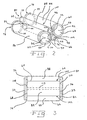
- Fig. 1 shows a press assembly 10, which is particularly useful in papermaking.
- the pressing assembly 10 comprises a frame 12, a loading cylinder 14, a pressing roller assembly 16, a clamping assembly 18, a diaphragm 20 and a control unit 21.
- the frame 12 includes a main frame 22, an upper swing frame 24, a lower swing frame 26, an upper swing arm 28, a lower swing arm 30 and a pair of side frames 32, 33.
- the side frame 32 is shown with a broken away portion to form an inner portion of the frame Side frame 33 uncover.
- the pivot arms 24, 26 are fixedly attached to the main frame 22 by, for example, welding or screwing.
- the pivot arms 28, 30 are each pivotally mounted on the pivot frames 24, 26 via a plurality of pivot pins 34 in a conventional manner.
- Each pivot arm 28, 30 has a first end 36, 38 each formed to receive opposite ends 40, 42 of the loading cylinder 14 via pivots 44.
- Each pivot arm 28, 30 has a second end 46, 48 which is formed, for example by welding or screws, that it firmly receives the respective bearing housing 50, 52.
- the first and second side frames 32, 33 are mounted on opposite sides of the main frame 22.
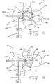
- the press roll assembly 16 includes a plurality of rollers 60, 62, 64, 66 (four rollers as shown) disposed in the frame 12 for cooperative rotation.
- cooperative rotation it is meant that the rotational speed at the peripheral surface of each of the rollers 60, 62, 64, 66 collectively is substantially equal, with substantially no slippage occurring between the roller surfaces.
- the rollers 60, 62 are referred to as main rollers and the rollers 64, 66 as pressure rollers.
- rollers 60, 62, 64, 66 closed hollow cylinder each having a first circular end 68, 70, 72, 74, a second circular end 76, 78, 80, 82 and a cylindrical, middle peripheral surface 84, 86, 88, 90, and they are all each radially symmetrically about an axis of rotation 92, 94, 96, 98.
- a set of seals 99 may be attached to the first circular ends 68, 70, 72, 74 and the second circular ends 76, 78, 80, 82.
- the main rollers 60, 62 and pressure rollers 64, 66 are arranged axially parallel.
- each pressure roller 64, 66 is smaller than the circumference of each main roller 60, 62.
- the rollers 60, 62, 64, 66 are arranged to define a corresponding number of nips 100, 102, 104, 106 ,
- the pressure rollers 64, 66 are used to provide a seal along the axial extent of the main rollers 60, 62 at the nips 100, 102, 104, 106.
- Each roller 60, 62, 64, 66 may comprise an elastic coating, such as rubber, to aid in sealing at the nips.
- the seal at the nips 100, 102, 104, 106 requires a relatively uniform pressure along all the nips 100, 102, 104, 106. With the likely deflection of the main rolls 60, 62 due to the application of force to them by the pressure rolls 64, 66 is either Mechanism necessary to support the creation of a uniform nip pressure at the nips 100, 102, 104, 106.
- the pressure rollers 64, 66 may use hydraulic pressure and a series of pistons within the roll shell of the rolls 64, 66 to force the roll shell of the rolls 64, 66 into the roll shell of the main rolls 60, 62 to apply a uniform pressure to the associated one Provide columns.
- a crowned or a deflection equalizing pressure roll could be used.
- the first and second side frames 32, 33 each include first and second sealing plates 108, 110, respectively, mounted to an inside thereof.
- the first and the second sealing plate 108, 110 are urged by the side frames 32, 33 to a part of the first circular ends 68, 70, 72, 74 and a part of the second circular ends 76, 78, 80, 82 of the rollers 60, 62, 64, 66 of the press roll assembly 16 to define a chamber 112 and thus effect an end seal of the chamber 112.
- at least one tie bar 113 is interposed between a first seal plate 108 and a second seal plate 110 in the chamber 112.
- first and second sealing plates 108, 110 are flexible and configured and configured to conform substantially to the shape of the first circular ends 68, 70, 72, 74 and second circular ends 76, 78, 80, respectively , 82 of the rollers 60, 62, 64, 66 adapt.
- seals are respectively disposed between the first and second sealing plates 108, 110 and the first and second circular ends 68, 70, 72, 74 and 76, 78, 80, 82, respectively.
- Such seals may include mechanical seals and fluid seals.
- the main rollers 60, 62 are fixedly rotatably mounted on the side frames 32, 33 using conventional bearing mounting structures such as those incorporating rolling bearings or bushings.
- firmly rotatably mounted means that the position of the axles 92, 94 of the rollers 60, 62 with respect to the main frame 22 and the side frames 32, 33 is not displaced following installation, but rotation about the axes 92, 94 is allowed.
- the main roll 60 which is in fluid communication with the chamber 112 via the membrane 20, includes at least one void in the form of a groove, a hole, and a pore formed in its central peripheral surface by a pressure differential across the membrane 20 and facilitate any intervening material, such as the continuous web 140.
- the main roll 62 which is not in fluid communication with the chamber 112 over the membrane 20, preferably does not include such a void in its central peripheral surface.
- Each roller may include an elastic coating, such as rubber, over all or part of its roller surface to assist in sealing the chamber 112 at the nips 100, 102, 104, 106.
- the pressure rollers 64, 66 are each rotatably mounted on bearing housings 50, 52. However, the axes of rotation 96, 98 of the rollers 64, 66 are movable with respect to the main frame 22 via pivot arms 28, 30, respectively, to effect loading of the press roller assembly 16. Since the circumference and corresponding diameter of each pressure roller 64, 66 is preferably less than the circumference and corresponding diameter of each main roller 60, 62, the forces generated on the pressure rollers 64, 66 are reduced, whereby smaller structures maintain forces within the chamber 112 can.
- the pressure rollers 64, 66 which are relatively smaller, require a lower actuation force than would a relatively larger counterpressure roller.
- the diameters of the pressure rollers 64, 66 are one third of the diameters of the main rollers 60, 62, the forces exerted on the pressure rollers 64, 66 can be reduced by 40 percent compared with the forces on the main rollers 60, 62.
- This arrangement allows the support structure, eg, the frame 12, to become simpler for the press roller assembly 16.
- the main rollers 60, 62 are mounted on bearings that are fixedly attached to the side frames 32, 33, which in turn are fixedly attached to the main frame 22.
- the tensioning assembly 18 includes a tensioning cylinder 114 and a tensioning roller 116.
- the tensioning roller 116 is rotatably coupled to the tensioning cylinder 114, which moves the tensioning roller 116 in a direction transverse to the axis of rotation of the tensioning roller 116.
- the membrane 20 moves in the direction of the arrow 118 and is passed over part of the peripheral surface 88 of the pressure roller 64, enters an inlet nip 100, passes over a part the circumferential surface 84 of the main roll 60 within the chamber 112, runs out of the outlet roll nip 102, passes over a portion of the peripheral surface 90 of the pressure roll 66, and passes about half of the peripheral surface of the tension roll 116.
- the membrane 20 is preferably a continuous band made of a semi-permeable material structured and configured to have a predetermined permeability allowing a predetermined flow of fluid therethrough.
- the semi-permeable membrane 20 is up to to a limited degree both gas permeable and liquid permeable.
- the membrane 20 is structured and configured to assist in sealing the chamber 112 at the inlet gap 100 and the outlet gap 102.
- the combined effect of the inlet gap 100, the membrane 20 running circumferentially around the main roll 60, and the outlet gap 102 serves to provide a single extended gap 115 for application of a mechanical seal Compressive force towards the main roll 60 and any intermediate material, which is arranged between the diaphragm 20 and the main roller 60 to form.
- the diaphragm 20 communicates with the pressurized chamber 112 and the main roll 60 to simultaneously effect a predetermined flow of fluid through the intervening material and a mechanical compressive force thereon.
- the membrane 20 is about 2.54 mm (0.1 inch) or less thick and comprises a forming fabric made semipermeable by having a plurality of interconnected pores 117 (shown by dots in FIG. 6). formed in the forming fabric having a size, shape, frequency and / or pattern selected to provide the desired permeability.
- the permeability is chosen to be greater than zero and less than about 0.025 m / s (five CFM per square foot) as measured by the TAPPI Test Method TIP 0404-20, and is most preferably chosen to be greater than Zero and less than about 0.010 m / s (two CFM per square foot). Therefore, semipermeable membrane 20 is both gas permeable and liquid permeable to a limited extent.
- the membrane 20 is made semi-permeable by starting from a carrier web that is highly permeable and then forming a plurality of interconnecting pores 117 in the carrier web.
- a batt is applied, which is made of a mixture of heat-fusible and non-heat-fusible fibers.
- the padding of the fiber mixture is sewn into the carrier fabric.
- Heat is applied to the sewn backing fabric to melt the heat fusible fibers, which in turn leave voids in the form of interconnecting pores similar to those of a foam sponge.
- the membrane 20 preferably comprises two tapered, impermeable, longitudinally extending outer edges 20A, 20B formed adjacent to the semipermeable portion of the membrane 20 with the interconnected pores 117.
- the outer edges 20A, 20B can be made impermeable by fusing heat-fusible fibers to the outer edges of the membrane 20 in the absence of non-heat-fusible fibers.
- the fiber blend may be sewn into the carrier web to form a drag layer near the surface of the membrane 20 that will be closest to the chamber 112.
- the pressure drop across the membrane 20 will occur near the chamber side surface of the membrane 20, causing the membrane 20 to entrain a minimal amount of chamber air.
- the membrane will release its entrained pressurized fluid as it flows out of the chamber, it is desirable to establish the entrained fluid volume as small as possible to avoid wastage under pressure set chamber fluid to avoid. Therefore, it is preferable to set the drag layer close to the chamber side surface of the membrane, and it is preferable to make the web as thin as possible, preferably less than 2.54 mm (0.1 inch).
- the percentage of membrane void space is low as possible, preferably less than 40 percent.
- the chamber-side surface is preferably also resistant to abrasion.
- the remainder of the web that does not comprise the fiber blend may act as a fluid distribution layer that receives fluid flow from the resistive layer and distributes the fluid flow across the underlying continuous web 140.
- the interconnecting pores 117 of the membrane 20 are formed by applying coating layers to the carrier web until the desired permeability is achieved.
- the permeability is adjusted by changing any parameter of: the type of coating, entrainment of air into the carrier to form a foam, and adjusting the solids content of the coating. The coating process is stopped when the desired flow resistance level of the membrane 20 is reached.
- the control unit 21 comprises a controller 120, a compressed air source 122, a fluid source 124, a differential pressure source 125 and a sensor assembly 126.
- the controller 120 preferably includes a microprocessor and memory for storing and executing a control program, and includes I / O means for establishing input / output communication and data transmission with external devices.
- controller 120 may be an industrial programmable controller of a type well known in the art.
- the compressed air source 122 comprises a plurality of individually controllable outputs.
- the compressed air source 122 is fluid-coupled to the loading cylinder 14 via a conduit 128.
- the compressed air source 122 is also fluid-coupled to the clamping cylinder 114 via line 130. While the preferred working fluid to operate the cylinders 14, 114 is compressed air, those skilled in the art will recognize that the compressed air system could be replaced with another fluid source using another gas or liquid working fluid.
- the fluid source 124 is fluidly coupled to the chamber 112 via line 132.
- the type of fluid is selectable by the user depending on the type of material the press assembly 10 processes. For example, in some applications, it may be desirable to use compressed dry air to pressurize the chamber 112 to a predefined pressure which, in preferred embodiments of the invention, is a pressure greater than 2.0684 Pa (30 psi) above pressure the differential pressure of the differential pressure source 125 is. In other applications, it may be desirable to use a pressurized gas, such as a heated gas, or a liquid, such as water, or a liquid solution.
- fluid flows into the chamber 112 via line 132 and exits the chamber 112 via the voids, for example, grooves, holes, or pores formed in the central peripheral surface 84 of the main roll 60.
- the voids in the main roll 60 communicate with the differential pressure source 125 via a conduit 133.
- the differential pressure source 125 may, for example a vacuum source, a pressure source operating at a pressure lower than the pressure in the chamber 112, or simply a vent to the atmosphere, coupled via line 133 to the interior of the roller 60 to evacuate the voids cause.
- venting via conduit 133 is not necessary if the main roll 60 includes grooved voids and the grooves communicate with atmospheric pressure.
- venting via line 133 may be eliminated if the roll voids, such as blind holes, are large enough and if they enter the gap at a pressure lower than the chamber pressure. In this case, the voids will act as a differential pressure source until the voids reach chamber pressure.
- the void size may be selected to control the effectiveness of the dewatering process.
- the pressurized chamber 112 includes its own pressure relief in that excessive pressure build-up in the chamber 112 will cause one or more rollers 60, 62, 64, 66 to open to vent the pressure, rather than causing catastrophic failure ,
- the controller 120 is electrically connected to the compressed air source 122 via an electrical cable 134 to selectively control the fluid output therefrom, thus independently controlling the operation of the loading cylinder 14 and placing a load on the pressure roller assembly 16, and independently operating the clamping cylinder 114 to control and thus create a predetermined voltage on the semipermeable membrane 20.
- the controller 120 is electrically connected to the fluid source 124 via an electrical cable 136.
- the controller 120 is also electrically connected to the sensor assembly 126 via an electrical cable 138.
- the sensor assembly 126 includes one or more sensor mechanisms to provide electrical feedback signals to the controller 120 that represent one or any combination of pressure, temperature, or other environmental factor within the chamber 112.
- the controller 120 processes the feedback signals to produce output signals that are provided to the fluid source 124 to selectively control the fluid output therefrom.
- the controller 120 processes feedback signals received from the sensor assembly 126 to preferably control a pressure of the pressurized chamber 112 to a pressure greater than 30 psi above the pressure of the differential pressure source 125.
- the rollers 60, 62, 64, 66 are rotated with little or no slippage between them, and the diaphragm 20 is driven at the same speed as the surface speed of the rollers 60, 62, 64, 66.
- a continuous web or web 140 and a web support layer 142 are introduced into the inlet nip 100 in the direction of arrow 143 and guided from the membrane 20 through the extended nip 115 to the exit nip 102.
- the membrane 20 is disposed within the roller assembly 16 so as to lie adjacent a first side 144 of the continuous web 140 to effectively separate its direct connection to the pressurized chamber 112. In other words, the fluid in the chamber 112 can not act on the continuous web 140 except through the membrane 20.
- the web support layer 142 is disposed so as to contact the cylindrical center surface 84 of the main roller 60, and is in contact with a second side 146 of the continuous web 140.
- the membrane 20 is structured and configured to have a permeability that permits predetermined fluid flow therethrough to the continuous web 140, and communicates with the pressurized chamber 112 and at least one void of the main roll 60 to communicate with one another Pressure difference across the membrane 20 and the continuous web 140 across. This pressure drop causes a mechanical compressive force to be applied to the continuous web 140 which helps to solidify it.
- the diaphragm 20 communicates with the pressurized chamber 112 and the main roll 60 to simultaneously effect a predetermined flow of fluid through the continuous web 140 as well as a mechanical compressive force thereon and thus provide improved drainage of the continuous web 140 promote.
- the dry content of the continuous web 140 prior to dewatering is greater than about 6 percent and less than about 70 percent, and if the basis weight of the continuous web 140 is greater than about 25 g / m 2 .
- the web support layer 142 preferably has a thickness of about 2.54 mm (0.1 inch) or less and may be a felt or alternatively comprise a felt disposed adjacent to a hydrophobic layer, the hydrophobic layer being adjacent the second side 146 the continuous web 140 is arranged.
- the web support layer 142 preferably comprises a felt layer 142A that is integral with a hydrophobic one Layer 142B is formed, wherein the hydrophobic layer 142B transports water by capillary action away from the continuous web 140, so that it is absorbed by the felt layer 142A (see Fig. 6).
- the hydrophobic layer 142B provides an effect of post-wetting protection, thereby preventing water from flowing back into the continuous web 140.
- the relative sizes of the mechanical pressure applied to the continuous web 140 are effected by factors such as the chamber pressure in the chamber 112, the permeability of the semipermeable membrane 20 and the permeability of the continuous web 140.
- the fluid flow, preferably air, through the continuous web 140 is influenced by factors such as the chamber pressure in the chamber 112, the permeability of the semipermeable membrane 20, and the size (eg, length) of the chamber 112.
- the dynamic fluid pressure in the pressurized chamber 112 is determined based on the monitoring of the Chamber pressure controlled by the sensor assembly 126.
- the sensor assembly 126 senses a pressure within the chamber 112 and provides a pressure feedback signal to the controller 120.
- the controller 120 processes the pressure feedback signal to produce a pressure output signal that is provided to the fluid source 124 to selectively control its fluid output and thus pressure pressurized chamber 112 at a predetermined pressure, preferably a pressure greater than 2.0684 Pa (30 psi) above the pressure of the differential pressure source 125 to control.
- a predetermined pressure preferably a pressure greater than 2.0684 Pa (30 psi) above the pressure of the differential pressure source 125 to control.
- the sensor assembly 126 may be adapted to detect a temperature within the chamber 112 and provide a temperature feedback signal.
- the controller 120 processes the temperature feedback signal together with the pressure feedback signal, to generate output signals which are supplied to the fluid source 124 to control the pressure and temperature in the pressurized chamber 112.
- the controller 120 also controls the loading of the main rollers 60, 62 by the pressure rollers 64, 66 by controlling a pressure magnitude that the loading cylinder 14 applies to the upper and lower pivot arms 28, 30.
- the load size of the main rollers 60, 62 is preferably related to a pressure in the pressurized chamber 112 that is monitored by a pressure sensor of the sensor assembly 126.
- the load may include a preload in addition to a load that is proportional to the pressure in the chamber 112.
- a lubricating and sealing fluid such as air or water or any viscous fluid may be used Fluid are forced into a plurality of seal openings 148 via a conduit ring 150, which is coupled to a fluid source 152 via a line 153.
- the pressurized fluid source 152 is electrically coupled to the controller 120 via an electrical cable 155 and is thereby controlled.
- the seal openings 148 in the seal plates 108, 110 are arranged to face the ends of the rollers 60, 62, 64, 66 to provide pressurized lubricating and sealing fluid between the seal plates 108, 110 and portions of the respective circular ends 68 , 70, 72, 74 and 76, 78, 80, 82. Due to the injection of the lubricating and sealing fluid, the sealing plates 108, 110 float over the circular ends 68, 70, 72, 74 and 76, 78, 80, 82 at small controllable distances with little or without physical contact between the sealing plates 108, 110 and the circular ends 68, 70, 72, 74 and 76, 78, 80, 82 of the rollers 60, 62, 64, 66. Although there is leakage around such a seal assembly, For example, the size of the leak is controllable to be small by the careful selection of spacing tolerances and the lubricating and sealing fluid.
- main roll 62 is also intended to include venting to a differential pressure source and continuous web 140, along with membrane 20, to be passed through all four columns, such as into gap 106, out of gap 104 into gap 100 and out of gap 102 to increase the residence time over which the membrane 20 interacts with the continuous web 140.
- Fig. 5 shows another variant in which the end seal of the chamber 112 is improved by arranging fluid apertures 154 in sealing plates 108, 110 so as to be close to the ends of the rollers 60, 62, 64, 66 but not facing them are.
- a conduit ring 156 is coupled to the ports 154 and coupled to the fluid source 152 via conduit 158 for supplying a lubricating and sealing fluid, such as air or water, or any other viscous fluid, through the ports 154 into the chamber 112.
- the fluid source 152 is electrically coupled to the controller 120 via electrical cables 155 and is thereby controlled.
- the pressure in the chamber 112 pushes the added fluid between the circular ends 68, 70, 72, 74 and 76, 78, 80, 82 of the rollers 60, 62, 64, 66 and the sealing plates 108, 110, respectively, thereby allowing in that the sealing plates 108, 110 float over the circular ends.
- the leakage is controlled by controlling the distance between the circular ends 68, 70, 72, 74 and 76, 78, 80, 82 of the rollers 60, 62, 64, 66 and sealing plates 108, 110 such that excessive leakage does not occur in any area , and that excessive wear between the sealing plates 108, 110 and rollers 60, 62, 64, 66 is prevented.
- FIG. 6 shows another variant in which a main roll 160 having the profile shown would replace the main roll 60.
- the main roll 160 includes a first circular end 162, a second circular end 164, a first cylindrical end surface 166 and a second cylindrical end surface 168, a first inclined annular surface 170, a second inclined annular surface 172 and a cylindrical central surface 174.
- the first cylindrical end surface 166 is disposed adjacent to the first circular end 162, and the second cylindrical end surface 168 is disposed adjacent to the second circular end 164.
- the cylindrical center surface 174 has a circumference smaller than the circumference of the first and second cylindrical end surfaces 166, 168.
- the first inclined annular surface 170 provides a transition from the cylindrical central surface 174 to the first cylindrical end surface 166
- the second inclined annular surface 172 provides a transition from the cylindrical central surface 174 to the second cylindrical end surface 168.
- the width of the central cylindrical surface 174 is selected to be approximately equal to the width of the diaphragm 20.
- the first and second inclined annular surfaces 170, 172 define a guide path for the membrane 20, the continuous web 140, and the web support layer 142.
- Each of the membrane 20 and the web support layer 142 preferably includes two tapered outer edges defining the first and second inclined annular surfaces 170, 172 touch.
- the permeable membrane 20 includes two tapered, impermeable, longitudinal ones extending outer edges 20A, 20B formed adjacent to a semipermeable portion 20C to enhance sealing along the inclined annular surfaces 170, 172.
- the web support layer 142 comprises a felt layer 142A and a hydrophobic layer 142B.
- the web support layer 142 may include two impermeable, longitudinally extending outer edges contacting the first and second inclined annular surfaces 170, 172.
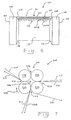
- a press assembly 200 comprises a roll assembly 201 having a plurality of rolls 202, 204, 206, 208 arranged in a quadrangular pattern for cooperative rotation in processing a first continuous web 209, such as a paper web. which is taken on a web support layer 210, and a second continuous web 212, such as a paper web, which is taken on a web support layer 214, is arranged.
- the web support layers 210, 214 may be felt layers, for example.
- Each of the plurality of rollers 202, 204, 206, 208 is of the type previously described as main rollers 60, 62, and / or 160 and pressure rollers 64, 66, and therefore will not be described again in detail. It is also to be understood that sealing plates of the same general type as described above with respect to the sealing plates 108 and 110 would be used in the manner described above with respect to Figs. 4 and 5 to accommodate a chamber 216 define. The control and pressure source ports for the chamber 216 and associated operation are as described above with respect to FIGS. 1-4, which is therefore not repeated here.
- rollers 202 and 204 are referred to as main rollers, and rollers 206, 208 are referred to as pressure rollers, although in the present embodiment rollers 202, 204, 206, 208 are approximately the same size.
- the main rollers 202, 204 and the pressure rollers 206, 208 are arranged to define a plurality of nips 220, 222, 224, 226, of which, based on the rotation of the main roller 202 in the direction shown by the arrow 230, the nips 220, 224 form inlet nip columns of the press assembly 200 and the nips 222, 226 form outlet nips.
- the first continuous web 209 and the first web support layer 210 enter the inlet nip 220 and are processed through the chamber 216 around the circumference of the main roll 202.
- the second continuous web 212 and the second web support layer 214 enter the inlet nip 224 and are processed through the chamber 216 around the peripheral surface of the main roll 204.
- the first web support layer 210, the continuous web 209, the continuous web 212 and the second web support layer 214 are processed through the exit nip 222 to form a laminated web 228 consisting of the continuous webs 209, 212.
- the second continuous web 212 remains in contact with the first continuous web 209 due to surface tension or due to venting in the main roll 202 through holes, grooves or pores formed in the cylindrical surface of the main roll 202. It is intended in that the second continuous web 212 and the second web support layer 214 could be replaced by a coating layer applied to the continuous web 209.
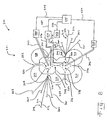
- a press assembly 300 includes a roller assembly 301 having a plurality of rollers 302, 304, 306, 308, 310, and 312 for cooperative rotation in processing a continuous web 314, such as a web Paper web, are arranged.
- Each roller 302, 304 is of the type previously described as main roller 60 and / or 160 and fluidly coupled to a differential pressure source in a manner described above.
- the rollers 306, 308, 310, 312 are of the type described above with respect to non-vented main and pressure rollers, such as the main roller 62 and the pressure roller 64, and therefore will not be described again in detail.
- the sealing plate 316 is of the same general type as described above with respect to the sealing plates 108 and 110 and may be used in the manner described above with respect to Figs. 4 and 5.
- rollers 302 and 304 are referred to as main rollers, and rollers 306, 308, 310, and 312 are referred to as pressure rollers because of their respective major function within a given chamber with respect to continuous web 314.
- the rollers 302, 304, 306, 308, 310 and 312 are approximately the same size.
- the main rollers 302, 304 and pressure rollers 306, 308, 310, 312 are arranged to define a plurality of nips 320, 322, 324, 326, 328, 330, 332, on the basis of which rotation of the main roller 302 in the direction indicated by the arrow As shown in FIG.
- the nips 320, 326, 330 form inlet nips of the press assembly 300
- the nips 322, 328, 332 form outlet nips
- the nip 324 is a chamber-dividing nip.
- the orientation and / or size of the rollers 302, 304, 306, 308, 310 and 312 may be modified such that the Nips are arranged at the desired locations and the processing efficiency is optimized.
- the sealing plates 316 together with the rollers 302, 304, 306, 308, 310 and 312, define a first chamber 336 and a second chamber 338, each chamber being associated with at least one inlet gap and at least one outlet gap.
- a first pressure source 340 is fluidly coupled to a chamber 336 via a conduit 342, and a second pressure source 344 is fluidly coupled to a chamber 338 via a conduit 346.
- the conduits 342 and 346 each extend from the seal plate 316 into the chambers 336 and 338, respectively, to disperse fluid flow therein.
- the controller 120 is electrically coupled to the pressure source 340 via an electrical cable 348 and is electrically coupled to the pressure source 344 via an electrical cable 350.
- a sensor assembly 352 is electrically connected to the controller 120 via an electrical cable 354. Sensor assembly 352 is configured to monitor the pressure and temperature of each chamber 336, 338.
- the pressing assembly 300 further includes a first semipermeable membrane 360 and a second semipermeable membrane 362.
- the membranes 360, 362 interact with the peripheral surfaces of the main rolls 302, 304 to define a first expanded gap 364 and a second expanded gap 366.
- the extended gap 364 is in the first chamber 336, and the extended gap 366 is in the second chamber 338.
- the continuous web 314 includes a first side 370 and a second side 372. While in the chamber 336, a fluid flows through the continuous web 314 in a first direction from the first side 370 to the second side 372 at the expanded gap 364. While in the chamber 338, fluid flows through the continuous web 314 in a second direction opposite to the first web a first diaphragm 360 communicates with the first chamber 336 and the main roll 302 to apply a mechanical pressing force to the continuous web 314 in the first direction; ie, apply from the first side 370 to the second side 372.
- a second diaphragm 362 communicates with the second chamber 338 and the main roller 304 to apply a mechanical pressing force to the continuous web 314 in the second direction, ie, from the second side 372 to the first side 370.
- the diaphragms 360, 362 communicate respectively with the respective pressurized chambers 336, 338 and the respective main rollers 302, 304 to simultaneously effect a predetermined fluid flow and a mechanical pressing force on the continuous web 314 in two directions in combination thus promoting improved dewatering of the continuous web 314.
- the main rollers 302, 304 each include at least one void, such as a hole, groove, or pore, to effect a pressure differential across the continuous web 314.
- each of the first semipermeable membrane 360 and the second semipermeable membrane 362 is fabricated from a forming fabric approximately 2.54 mm (0.1 inch) or less thick and semi-permeable by having a plurality of interconnected pores 117 in the formed fabric having a size , Form, frequency, and / or patterns selected to provide the desired permeability, as described more fully above in connection with the membrane 20 is.
- the permeability of each of the first semipermeable membrane 360 and the second semipermeable membrane 362 is selected to be greater than zero and less than about 0.025 m / s (five CFM per square foot), as determined by the TAPPI test method TIP 0404- 20, and in particular greater than zero and less than about 0.01 m / s (two CFM per square foot).
- the press assembly 300 further includes a first web support layer 361 and a second web support layer 363 disposed on opposite sides of the continuous web 314, respectively.
- the first web support layer 361 is disposed between the membrane 362 and the rollers 302 and 312, and the second web support layer 363 is disposed between the diaphragm 360 and the rollers 306 and 304.
- the first web support layer 361 may be disposed between the continuous web 314 and the membrane 362, and the second web support layer 363 may be disposed between the continuous web 314 and the membrane 360.
- each of the web support layers 361, 363 is an integral web having a felt layer and a hydrophobic layer having a total thickness of about 2.54 mm (0.1 inch) or less and is oriented such that the hydrophobic layer is continuous Web 314 faces.
- the expanded gaps 364 and 366 are substantially the same length.
- the gap lengths may be different, which may, for example, be effected by selecting main rollers of different circumferences and / or varying the circumferential size of any one or more of the pressure rollers to effectively change the location of one or more nips 320, 324, and 328.
- each of the first chamber 336 and the second chamber 338 is individually controlled by the controller 120 and can be pressurized to different pressures.
- the chamber 338 is preferably pressurized to a pressure greater than the pressure of the chamber 336.
- Such materials may include dry air, steam or gas, water or other fluid.
- FIG. 8 further shows a temperature control unit 374 fluidly coupled via conduits 376, 378 to respective chambers 336, 338 to supply a heating or cooling fluid, such as air, to the chambers 336, 338.
- the temperature control unit 374 is electrically coupled to the controller 120 via an electrical cable 380.
- the controller 120 receives temperature signals representing the temperatures of the chambers 336, 338 from the sensor assembly 352.
- the controller 120 uses these temperatures to generate temperature output signals based on predefined target temperatures that are provided to the temperature control unit 374.
- the temperature control unit 374 then responds to the temperature output signals to control the temperatures of the chambers 336, 338.
- the temperature of the chamber 338 is preferably controlled to be higher than the temperature of the chamber 336.
- the temperature control of the chambers 336, 338 may be effected by respectively controlling the temperature of the fluids supplied by the first pressure source 340 and / or the second fluid source 344 to the respective chambers 336, 338.
- the temperature control unit 374 may be eliminated.
- Fig. 9 shows a part of the roller assembly 400 comprising a main roller 402 and a pressure roller 404 which may be used in place of the above-described main rollers or pressure rollers.
- the main roller 402 has a general structure that corresponds to that of the main roller 160 shown in FIG. 6. While only a right end portion 406 of the main roll 402 is shown in FIG. 9, it will be appreciated that the left end of the roll 402 is a mirror image of the right end 406 and thus the same reference numerals used to describe the right end 406 , apply to the left end of the main roll 402.
- the main roller 402 includes a cylindrical center surface 408, left and right circular ends 410, left and right cylindrical end surfaces 412, and left and right inclined annular surfaces 414.
- the cylindrical end surfaces 412 are disposed adjacent to respective circular ends 410.
- the cylindrical center surface 408 has a circumference smaller than the circumference of the cylindrical end surfaces 412.
- the inclined annular surfaces 414 provide a transition from the cylindrical central surface 408 to the cylindrical end surfaces 412.
- the central cylindrical surface 408 includes at least one void, such as a groove, a hole or a pore, to facilitate a pressure differential across the membrane 20 and any intervening material.
- the distance between the inclined annular surfaces 414 of the main roller 402 is set to be approximately equal to the width of the semipermeable membrane 20.
- the inclined annular surfaces 414 define a guide path for the semipermeable membrane 20 and the backing layer 142.
- each of the semi-permeable membrane 20 and the backing layer 142 includes two tapered outer edges that contact the inclined annular surfaces 414.
- the semi-permeable membrane 20 includes two tapered, impermeable, longitudinally extending outer edges 20A, 20B (see FIG. 6) to enhance sealing along the inclined annular surfaces 414.
- the web support layer 142 comprises a felt layer 142A and a hydrophobic layer 142B.
- the profiles of the semipermeable membrane 20 and the web support layer 142 are preferably sized to fit into the roll profile of the main roll 402 between the inclined annular surfaces 414 such that the membrane 20 and the cylindrical end faces 412 have substantially the same peripheral height.
- a continuous web such as a paper web (not shown) would be disposed between the semipermeable membrane 20 and the web support layer 142.
- Interchangeable end seals 416 are attached to the circular ends 410, which include a plurality of fluid cavities 418. The attachment is effected by adhesive or fasteners.
- the replaceable end seals 416 are preferably made of a resilient material, such as rubber, and may include a reinforcing fabric, such as nylon or steel.
- the pressure roller 404 includes a generally cylindrical structure that corresponds to that of the pressure roller 64 shown in Figs.
- FIG. 9 While only a right end portion 420 of the pressure roller 404 is shown in FIG. 9, it will be appreciated that the left end of the pressure roller 404 is a mirror image of the right end 420 and thus the same reference numerals used to describe the right end 420 , apply to the left end of the pressure roller 404.
- the pressure roller 404 includes a cylindrical central surface 422 and left and right circular ends 424.
- a sealing sleeve 426 having an inner surface 428 and an outer surface 430 is received over the cylindrical central surface 422 and held in a fixed relationship with the pressure roller 404 due to frictional forces between the cylindrical central surface 422 and the inner surface 428 of the sealing sleeve 426 act.
- the sealing sleeve 426 may be held in place by adhesive or by fasteners disposed below the outer surface 430 of the sealing sleeve 426 and received in the cylindrical central surface 422.
- each sealing sleeve 426 is replaceable such that when the sealing sleeve 426 shows an unacceptable level of wear, the sealing sleeve 426 can be replaced without the need to discard the pressure roller 404.
- the sealing sleeve 426 includes a stress layer 432 and a plurality of fluid cavities 434.
- Interchangeable end seals 436 which include a plurality of fluid cavities 438, are attached to the circular ends 424. The attachment is effected by means of adhesive or fasteners.
- the replaceable end seals 436 are preferably made of a resilient material, such as rubber, and may include a reinforcing fabric, such as nylon or steel.
- the sealing sleeve 426 is preferably made of an elastic material such as rubber.
- the stress layer 432 of the sealing sleeve 426 is used to hold the hoop or strapping stresses and / or stresses of the sealing sleeve 426 across the machine and includes a reinforcing fabric such as nylon or steel.
- the size, shape and geometry of the fluid cavities 434 are selected to be elastically deformable, particularly in the vicinity of the longitudinally extending edges 20A, 20B of the semipermeable membrane 20.
- the fluid cavities 434 extend either circumferentially around the sealing sleeve 426 in a repeated pattern across the width of the pressure roller 404 or across the width of the pressure roller 404 in a repeated pattern around the circumference of the sealing sleeve 426.
- the cavities 434 may extend diagonally around the sealing sleeve 426.
- the fluid cavities 434 are pressurized with a fluid such as air, water or gel to maintain a compliant but tight seal with the semipermeable membrane 20 about the cylindrical end surfaces 412 of the main roll 402.
- the fluid cavities 434 are pressurized at the time of manufacture of the sealing sleeve 426.
- the compressed air cavities 434 are not pressurized at the time of manufacturing the sealing sleeve 426, but rather, the sealing sleeve 426 may include one or more valve ports 440, such as the type commonly used to introduce air into a pneumatic tire to receive fluid and thus pressurize the cavities 434.
- valve port (s) 440 may be open ports connected to a fluid source via a fluid conduit and a rotatable fluid coupling.
- the fluid cavities 418, 438 of the interchangeable end seals 416, 436 are pressurized with a fluid, such as air, water or gel.
- a fluid such as air, water or gel.
- the size, shape and geometry of the cavities 418, 438 are selected to be elastically deformable to provide a compliant but firm seal between the interchangeable end seals 416, 436 and associated sealing plates, such as the seal plates 108, 110 of FIG. 3 to uphold.
- the fluid cavities 418, 438 are pressurized at the time of manufacture of the end seals 416, 436.
- the fluid cavities 418, 438 are not pressurized at the time of manufacture of the end seals 416, 436.
- interchangeable end seals 416, 436 may each include one or more valve ports 442, 444, such as, for example, the type commonly used to introduce air into a pneumatic tire to receive fluid, thus exposing cavities 418, 438 To put pressure.
- valve ports 442, 444 such as, for example, the type commonly used to introduce air into a pneumatic tire to receive fluid, thus exposing cavities 418, 438 To put pressure.
- the respective membrane can be seen in each case.
- a membrane can also be used in particular in the embodiments be provided according to Figures 12 and 13. Again, the membrane is conveniently located back on the higher pressure side of the fibrous web.
- a membrane made of sheet material having through holes may be used.
- the pressure of the displacement fluid acting on the membrane is preferably greater than the ambient pressure.
- a membrane can also be used again, as has been described above.
- the membrane may in particular be provided with contiguous pores.
- the fibrous web 12 may in particular be a paper or board web.
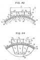
- the dewatering device 10 comprises a dewatering zone E, in which the fibrous web 12 is at least partially dewatered by application of pressurized displacement fluid, in particular displacement gas 14.
- the fibrous web 12 is guided together with a membrane 16 and a wire or felt belt 18 through the dewatering device 10, wherein the fibrous web 12 is applied through the membrane 16 through the displacement gas 14.
- the screen or felt belt 18 is located on the opposite side of the fibrous web 12. The fibrous web 12 is thus guided between the pressurized gas membrane 16 and the wire or felt belt 18 through the dewatering zone E.
- the dewatering zone E comprises a gas pressure-supplying displacement dewatering unit 20 which faces with its gas outlet side 25 of a formed for example by a roller mating surface 24 to form with this a lengthened in web direction L gap 26 through which the membrane 16, the sieve - or felt 18 and the intermediate fibrous web 12 are passed.
- the dewatering zone E is subdivided into a plurality of sections in which the applied gas pressure can be set individually.
- the applied gas pressure can be set individually.
- three such sections E1, E2 and E3 are provided.
- any other number of sections is possible. So are in particular four or more sections conceivable.
- the pressures prevailing in the various sections E1, E2 and E3 are indicated in FIG. 10 by p 1 , p 2 and p 3 .
- the different sections Ei i.
- the sections E1, E2 and E3 may be sectioned across the width, i. It can be provided across the width of different pressures.
- the mating surface 24 may be closed, open (grooved, ...) or permeable.
- a box 28 which receives the liquid and / or the gas, can be arranged behind the mating surface 24 in the dewatering direction.
- the box 28 can be vacuumed, i. be provided as a suction box.
- several zones Si can be provided in the web running direction L, which can be subjected to different pressures (for example, overpressing and / or suppressing).
- three zones S1, S2 and S3 are provided. In principle, however, any other number of zones is possible here as well.
- a discharge of liquid or gas is possible.
- FIG. 11 has at least substantially the same structure as that of FIG. 10. Corresponding parts are assigned the same reference numerals.
- the result of the displacement dewatering process in terms of the final dry content and paper properties of the finished fibrous web 12, such as the specific volume, the porosity, the Surface roughness and / or the like can be controlled specifically.
- the applied gas pressure along the dewatering zone may be varied as desired.
- the dewatering process can be set directly during operation. In this case, for example, a gentle initial drainage can be carried out at a low gas pressure. If a high final dry content is required, so that the gas pressure in the rear sections of the dewatering zone E can be increased accordingly. If, on the other hand, a high volume is required for the finished fibrous web 12, then the gas pressure in the rear sections of the dewatering zone E can be set correspondingly low. It is thus in particular also a respective pressure profile, for example adjustable in the machine direction.
- a membrane can again be used, as has been described in connection with the first aspect of the invention.
- the membrane may in particular also be provided with contiguous pores.
- the fibrous web 12 shows a schematic representation of a first embodiment of a device 10 for dewatering a fibrous web 12.
- the fibrous web 12 may in particular be a paper or board web.
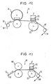
- the dewatering device 10 comprises a displacement dewatering zone E, in which the fibrous web 12 is at least partially dewatered by an application of displacement fluid, in this case, for example, displacement gas 14.
- displacement fluid in this case, for example, displacement gas 14.
- the displacement dewatering zone E is preceded by a press 16.
- the fibrous web 12 is first passed through the upstream press 16 and then through the displacement dewatering zone E.
- the upstream press 16 is formed by a shoe press.
- the fibrous web 12 is guided in the present embodiment, together with a wire or felt belt 18 through the press 16 and the displacement dewatering zone E.
- the dewatering zone E comprises a displacement dewatering unit 20 which, with its gas outlet side, faces a counter-roller 22, via which the fibrous web 12 and the sieve or felt belt 18 acted upon by the displacement gas 14 are guided.
- FIG. 13 differs from that of FIG. 12 only in that a roll press is provided as the press 16 'upstream of the displacement dewatering zone E.
- this dewatering apparatus 10 has the same construction as the apparatus shown in FIG. 12. Corresponding parts are assigned the same reference numerals.
- a downstream mechanical press can also be provided.
- the amount of blade compression and the amount of applied gas pressure can be controlled separately.
- the nonwoven fabric By means of the press preceding the displacement dewatering zone, the nonwoven fabric can be precompacted to the desired degree. In this way, the permeability of the nonwoven fabric can be adjusted in the desired manner.
- the properties of the finished paper can be adjusted specifically. If the fleece is heavily precompacted, more water can be removed from the fleece. This is particularly necessary for those types of paper where a high dry content after the press is required in the first place.
- a membrane can again be used, as has been described in connection with the first aspect of the invention.
- the membrane may in particular also be provided with contiguous pores.
Claims (18)
- Procédé pour la déshydratation d'une nappe fibreuse (12), notamment d'une nappe de papier ou de carton, dans lequel la nappe fibreuse (12) est guidée à travers une zone de déshydratation dans laquelle elle est déshydratée au moins en partie par une sollicitation avec un fluide de déplacement sous pression, en particulier du gaz de déplacement, et dans lequel la nappe fibreuse (12) est guidée conjointement avec une membrane poreuse (20) à travers la zone de déshydratation et est sollicitée à travers la membrane (20) par le fluide de déplacement, caractérisé en ce que l'on utilise comme membrane poreuse (20) une membrane dont l'épaisseur est d'environ 2,54 mm ou moins, et qui comprend une toile de formation avec plusieurs pores (117) connectés les uns aux autres, qui présente une perméabilité qui est supérieure à zéro et inférieure à environ 0,025 m/s, telle que mesurée par le procédé de test TAPPI TIP 0404-20.
- Procédé selon la revendication 1,
caractérisé en ce que
l'on utilise comme membrane (20) une membrane constitué de matériau en feuille avec des trous de passage. - Procédé selon la revendication 1 ou 2,
caractérisé en ce que
la pression du fluide de déplacement sollicitant la membrane (20) est supérieure à la pression de l'environnement. - Procédé selon l'une quelconque des revendications 1 à 3,
caractérisé en ce que
la perméabilité est supérieure à zéro et inférieure à 0,01 m/s. - Procédé selon l'une quelconque des revendications 1 à 3,
caractérisé en ce que
la perméabilité est déterminée par au moins un facteur parmi les facteurs de taille, de forme, de fréquence et de motif d'une pluralité de pores dans la toile de formation. - Procédé selon l'une quelconque des revendications 1 à 3,
caractérisé en ce que
la membrane (20) possède une couche résistant à l'écoulement à proximité de sa surface. - Procédé selon la revendication 6,
caractérisé en ce que
la membrane (20) comprend une couche de répartition de fluide à côté de la couche résistant à l'écoulement. - Procédé selon l'une quelconque des revendications 1 à 3,
caractérisé en ce que
la membrane (20) comprend une surface résistant à l'abrasion. - Procédé selon l'une quelconque des revendications 1 à 3,
caractérisé en ce que
le pourcentage d'espace vide de la membrane est inférieur à 40 pour cent. - Procédé selon l'une quelconque des revendications 1 à 3,
caractérisé en ce que
la membrane (20) est fabriquée selon un procédé qui comprend les étapes suivantes :on fournit une toile de support qui est perméable et on forme plusieurs pores (117) connectés les uns aux autres dans la toile de support,pour la formation d'une portion semi-perméable de la membrane présentant les pores (117) connectés les uns aux autres on mélange des fibres thermofusibles et des fibres non thermofusibles,le mélange de fibres est cousu dans la toile de support et on applique de la chaleur afin de faire fondre les fibres thermofusibles en laissant les espaces vides en forme de pores (117) connectés les uns aux autres, eton forme deux portions de bord (20A, 20B) s'étendant dans la direction longitudinale de la membrane (20), entre lesquelles la section semi-perméable est disposée,la membrane (20) présentant une épaisseur inférieure à 2,54 mm et la section semi-perméable présentant une perméabilité supérieure à zéro etinférieure à 0,025 m/s, telle que mesurée par le procédé de test TAPPI TIP 0404-20. - Procédé selon la revendication 10,
caractérisé en ce que
l'étape de couture comprend l'étape consistant à coudre le mélange de fibres dans la toile de support afin de former à proximité de la surface de la membrane (20) une couche résistant à l'écoulement. - Procédé selon la revendication 11,
caractérisé en ce que
le procédé comprend l'étape consistant à définir une couche de répartition de fluide dans la membrane (20) par le reste de la toile de support ne présentant pas le mélange de fibres, ladite couche recevant un écoulement de fluide de la couche résistant à l'écoulement et le répartissant. - Procédé selon la revendication 10,
caractérisé en ce que
les portions de bord (20A, 20B) s'étendant dans la direction longitudinale de la membrane (20) sont formées de manière imperméable. - Procédé selon les revendications 11 et 12,
caractérisé en ce que
l'étape de formation comprend les étapes consistant à former à la fois la couche résistant à l'écoulement et la couche de répartition de fluide. - Procédé selon l'une quelconque des revendications 1 à 3,
caractérisé en ce que
l'on fournit une toile de support perméable et la pluralité de pores connectés les uns aux autres est formée dans la toile de support, l'étape de formation comprenant l'étape consistant à appliquer des couches de revêtement sur la toile de support jusqu'à ce que l'on ait atteint la perméabilité souhaitée. - Procédé selon la revendication 15,
caractérisé en ce que
le procédé comprend l'étape consistant à modifier le type de revêtement afin d'ajuster la perméabilité. - Procédé selon la revendication 15,
caractérisé en ce que
le procédé comprend l'étape consistant à entraîner de l'air à l'intérieur du revêtement afin d'ajuster la perméabilité. - Procédé selon la revendication 15,
caractérisé en ce que
le procédé comprend l'étape consistant à ajuster la teneur en matières solides du revêtement afin d'ajuster la perméabilité.
Applications Claiming Priority (7)
| Application Number | Priority Date | Filing Date | Title |
|---|---|---|---|
| DE1999146982 DE19946982A1 (de) | 1999-09-30 | 1999-09-30 | Verfahren und Vorrichtung zur Entwässerung einer Faserstoffbahn |
| US409794 | 1999-09-30 | ||
| DE19946982 | 1999-09-30 | ||
| US09/409,794 US6645420B1 (en) | 1999-09-30 | 1999-09-30 | Method of forming a semipermeable membrane with intercommunicating pores for a pressing apparatus |
| DE19946984 | 1999-09-30 | ||
| DE1999146984 DE19946984A1 (de) | 1999-09-30 | 1999-09-30 | Verfahren und Vorrichtung zur Entwässerung einer Faserstoffbahn |
| EP00120661A EP1088933B1 (fr) | 1999-09-30 | 2000-09-21 | Membrane semiperméable avec pores interconnectés pour une presse |
Related Parent Applications (1)
| Application Number | Title | Priority Date | Filing Date |
|---|---|---|---|
| EP00120661A Division EP1088933B1 (fr) | 1999-09-30 | 2000-09-21 | Membrane semiperméable avec pores interconnectés pour une presse |
Publications (2)
| Publication Number | Publication Date |
|---|---|
| EP1362948A1 EP1362948A1 (fr) | 2003-11-19 |
| EP1362948B1 true EP1362948B1 (fr) | 2006-08-09 |
Family
ID=27219303
Family Applications (4)
| Application Number | Title | Priority Date | Filing Date |
|---|---|---|---|
| EP00120661A Expired - Lifetime EP1088933B1 (fr) | 1999-09-30 | 2000-09-21 | Membrane semiperméable avec pores interconnectés pour une presse |
| EP03016714A Expired - Fee Related EP1362949B1 (fr) | 1999-09-30 | 2000-09-21 | Procédé et dispositif pour la déshydratation d' une bande fibreuse |
| EP03016715A Expired - Lifetime EP1362950B1 (fr) | 1999-09-30 | 2000-09-21 | Procédé et dispositif pour la déshydratation d' une bande fibreuse |
| EP03016713A Expired - Fee Related EP1362948B1 (fr) | 1999-09-30 | 2000-09-21 | Procédé pour la déshydratation d' une bande fibreuse |
Family Applications Before (3)
| Application Number | Title | Priority Date | Filing Date |
|---|---|---|---|
| EP00120661A Expired - Lifetime EP1088933B1 (fr) | 1999-09-30 | 2000-09-21 | Membrane semiperméable avec pores interconnectés pour une presse |
| EP03016714A Expired - Fee Related EP1362949B1 (fr) | 1999-09-30 | 2000-09-21 | Procédé et dispositif pour la déshydratation d' une bande fibreuse |
| EP03016715A Expired - Lifetime EP1362950B1 (fr) | 1999-09-30 | 2000-09-21 | Procédé et dispositif pour la déshydratation d' une bande fibreuse |
Country Status (2)
| Country | Link |
|---|---|
| EP (4) | EP1088933B1 (fr) |
| DE (4) | DE50009970D1 (fr) |
Families Citing this family (7)
| Publication number | Priority date | Publication date | Assignee | Title |
|---|---|---|---|---|
| US6616812B2 (en) * | 2001-09-27 | 2003-09-09 | Voith Paper Patent Gmbh | Anti-rewet felt for use in a papermaking machine |
| US6702924B2 (en) | 2001-09-27 | 2004-03-09 | Voith Paper Patent Gmbh | Main roll for an air press of a papermaking machine |
| DE10159411A1 (de) * | 2001-12-04 | 2003-06-12 | Voith Paper Patent Gmbh | Vorrichtung zur Entwässerung einer Faserstoffbahn |
| GB0130431D0 (en) * | 2001-12-20 | 2002-02-06 | Voith Fabrics Heidenheim Gmbh | Permeable membrane |
| DE10304575A1 (de) * | 2003-02-05 | 2004-08-19 | Voith Paper Patent Gmbh | Pressspaltanordnung |
| US6875310B2 (en) | 2003-03-26 | 2005-04-05 | Voith Paper Patent Gmbh | Roll configuration for an air press of a papermaking machine |
| DE102006000053A1 (de) | 2006-02-08 | 2007-08-09 | Voith Patent Gmbh | Verfahren und Maschine zur Herstellung einer Faserstoffbahn |
Family Cites Families (13)
| Publication number | Priority date | Publication date | Assignee | Title |
|---|---|---|---|---|
| CH563867A5 (fr) * | 1973-03-01 | 1975-07-15 | Escher Wyss Gmbh | |
| US3970515A (en) * | 1973-11-05 | 1976-07-20 | Beloit Corporation | Controlled sequence pressure nip |
| AT380907B (de) * | 1981-01-27 | 1986-07-25 | Escher Wyss Gmbh | Nasspresse mit verlaengertem pressspalt fuer papiermaschinen |
| FI70952C (fi) * | 1982-10-14 | 1986-10-27 | Valmet Oy | Anordning med laong presszon vid pressbehandling av fiberbana |
| US4675079A (en) * | 1982-12-14 | 1987-06-23 | Webster David R | Multi-nip suction press with a four roller closed train |
| DD222680A1 (de) * | 1984-04-03 | 1985-05-22 | Wtz Zellstoff Papierind | Verfahren zur entwaesserung von faserstoffbahnen |
| DE3728124A1 (de) * | 1987-08-22 | 1989-03-02 | Escher Wyss Gmbh | Entwaesserungspresse mit dampfzufuhr |
| US4888096A (en) * | 1987-12-02 | 1989-12-19 | Inotech Process Ltd. | Roll press for removing water from a web of paper using solid grooved roll and compressed air |
| DE4028085C1 (fr) * | 1990-09-05 | 1992-02-27 | Thomas Josef Heimbach Gmbh & Co, 5160 Dueren, De | |
| GB9404960D0 (en) * | 1994-03-15 | 1994-04-27 | Scapa Group Plc | Belt for long nip dewatering presses |
| US5700356A (en) * | 1996-01-19 | 1997-12-23 | Lefkowitz; Leonard R. | Air permeable belt for dewatering web in press nip |
| DE19653508A1 (de) * | 1996-10-16 | 1998-04-23 | Voith Sulzer Papiermasch Gmbh | Schuhpresse |
| WO1999023296A1 (fr) * | 1997-10-31 | 1999-05-14 | Beloit Technologies, Inc. | Presse a air |
-
2000
- 2000-09-21 EP EP00120661A patent/EP1088933B1/fr not_active Expired - Lifetime
- 2000-09-21 DE DE50009970T patent/DE50009970D1/de not_active Expired - Lifetime
- 2000-09-21 DE DE50013339T patent/DE50013339D1/de not_active Expired - Fee Related
- 2000-09-21 DE DE50013759T patent/DE50013759D1/de not_active Expired - Fee Related
- 2000-09-21 EP EP03016714A patent/EP1362949B1/fr not_active Expired - Fee Related
- 2000-09-21 DE DE50013312T patent/DE50013312D1/de not_active Expired - Fee Related
- 2000-09-21 EP EP03016715A patent/EP1362950B1/fr not_active Expired - Lifetime
- 2000-09-21 EP EP03016713A patent/EP1362948B1/fr not_active Expired - Fee Related
Also Published As
| Publication number | Publication date |
|---|---|
| EP1362950A1 (fr) | 2003-11-19 |
| DE50013339D1 (de) | 2006-09-28 |
| EP1362949A1 (fr) | 2003-11-19 |
| EP1362950B1 (fr) | 2006-11-15 |
| EP1088933A3 (fr) | 2002-08-21 |
| EP1362949B1 (fr) | 2006-08-16 |
| EP1362948A1 (fr) | 2003-11-19 |
| EP1088933A2 (fr) | 2001-04-04 |
| DE50013312D1 (de) | 2006-09-21 |
| DE50009970D1 (de) | 2005-05-12 |
| EP1088933B1 (fr) | 2005-04-06 |
| DE50013759D1 (de) | 2006-12-28 |
Similar Documents
| Publication | Publication Date | Title |
|---|---|---|
| EP0496965B1 (fr) | Section de presse | |
| EP0988417B1 (fr) | Secherie | |
| DE3920742A1 (de) | Walze fuer eine presse einer papiermaschine oder dergleichen | |
| DE602004011680T2 (de) | Trägerkörper, halter dafür, vorrichtung mit dem träger zur behandlung einer bahn, verfahren zur ausbildung eines längeren walzenspalts in der vorrichtung und zur gezielten einstellung des liniendrucks im walzenspalt | |
| EP1362948B1 (fr) | Procédé pour la déshydratation d' une bande fibreuse | |
| EP1660720A1 (fr) | Dispositif de guidage de bande | |
| DE10322519A1 (de) | Bahnführungseinrichtung | |
| EP0949375A2 (fr) | Dispositif pour transférer une bande fibreuse | |
| DE60029892T2 (de) | Pressenvorrichtung mit einer Membrane | |
| DE102004017807A1 (de) | Trockenanordnung | |
| DE10259232A1 (de) | Vorrichtung zum Bilden eines Langspalts | |
| DE10351294A1 (de) | Anpresseinrichtung | |
| AT255884B (de) | Verfahren und Vorrichtung zum Herstellen einer ein- oder beidseitig geglätteten Papierbahh od. dgl. | |
| DE10322525A1 (de) | Bahnführungseinrichtung | |
| DE102005020220A1 (de) | Langspaltpresse | |
| DE60020265T2 (de) | Verfahren und vorrichtung zum pressen einer papierbahn | |
| DE102004017829A1 (de) | Trockenanordnung | |
| WO2016016077A1 (fr) | Dispositif de déshydratation permettant la déshydratation d'une bande de matière fibreuse, procédé de déshydratation d'une bande de matière fibreuse ainsi que machine de production d'une bande de matière fibreuse | |
| EP1479818B1 (fr) | Dispositif de guidage pour guider une bande | |
| DE60009119T2 (de) | Verfahren zur querrichtungsprofilierung einer papier- oder pappebahn in einem spalt | |
| DE102020116216A1 (de) | Verfahren zur variablen Einstellung der Entwässerungsleistung einer Pressvorrichtung | |
| EP1880055B1 (fr) | Presse a sabot | |
| DE102005046323A1 (de) | Schuhpresse zum Auspressen einer laufenden feuchten Bahn, insbesondere einer Faserstoffbahn | |
| DE10322516A1 (de) | Bahnführungseinrichtung | |
| EP2071075A1 (fr) | Dispositif de formation d'une pince élargie |
Legal Events
| Date | Code | Title | Description |
|---|---|---|---|
| PUAI | Public reference made under article 153(3) epc to a published international application that has entered the european phase |
Free format text: ORIGINAL CODE: 0009012 |
|
| AC | Divisional application: reference to earlier application |
Ref document number: 1088933 Country of ref document: EP Kind code of ref document: P |
|
| AK | Designated contracting states |
Kind code of ref document: A1 Designated state(s): DE FI SE |
|
| RIN1 | Information on inventor provided before grant (corrected) |
Inventor name: DAHL, HANS, DR. Inventor name: VOMHOFF, HANNES, DR. Inventor name: ELENZ, THOMAS, DR. Inventor name: GRABSCHEID, JOACHIM, DR. Inventor name: MIRSBERGER, PETER Inventor name: BECK, DAVID ALLEN Inventor name: BOECK, KARL JOSEF Inventor name: BEGEMANN, ULRICH |
|
| 17P | Request for examination filed |
Effective date: 20031222 |
|
| AKX | Designation fees paid |
Designated state(s): DE FI SE |
|
| 17Q | First examination report despatched |
Effective date: 20040907 |
|
| GRAP | Despatch of communication of intention to grant a patent |
Free format text: ORIGINAL CODE: EPIDOSNIGR1 |
|
| GRAS | Grant fee paid |
Free format text: ORIGINAL CODE: EPIDOSNIGR3 |
|
| GRAA | (expected) grant |
Free format text: ORIGINAL CODE: 0009210 |
|
| AC | Divisional application: reference to earlier application |
Ref document number: 1088933 Country of ref document: EP Kind code of ref document: P |
|
| AK | Designated contracting states |
Kind code of ref document: B1 Designated state(s): DE FI SE |
|
| PG25 | Lapsed in a contracting state [announced via postgrant information from national office to epo] |
Ref country code: FI Free format text: LAPSE BECAUSE OF FAILURE TO SUBMIT A TRANSLATION OF THE DESCRIPTION OR TO PAY THE FEE WITHIN THE PRESCRIBED TIME-LIMIT Effective date: 20060809 |
|
| RAP2 | Party data changed (patent owner data changed or rights of a patent transferred) |
Owner name: VOITH PATENT GMBH |
|
| REF | Corresponds to: |
Ref document number: 50013312 Country of ref document: DE Date of ref document: 20060921 Kind code of ref document: P |
|
| PG25 | Lapsed in a contracting state [announced via postgrant information from national office to epo] |
Ref country code: SE Free format text: LAPSE BECAUSE OF FAILURE TO SUBMIT A TRANSLATION OF THE DESCRIPTION OR TO PAY THE FEE WITHIN THE PRESCRIBED TIME-LIMIT Effective date: 20061109 |
|
| PG25 | Lapsed in a contracting state [announced via postgrant information from national office to epo] |
Ref country code: DE Free format text: LAPSE BECAUSE OF NON-PAYMENT OF DUE FEES Effective date: 20070403 |
|
| PLBE | No opposition filed within time limit |
Free format text: ORIGINAL CODE: 0009261 |
|
| STAA | Information on the status of an ep patent application or granted ep patent |
Free format text: STATUS: NO OPPOSITION FILED WITHIN TIME LIMIT |
|
| 26N | No opposition filed |
Effective date: 20070510 |