EP1362003B1 - Belastungs-überwachungssystem für fördergutträger - Google Patents
Belastungs-überwachungssystem für fördergutträger Download PDFInfo
- Publication number
- EP1362003B1 EP1362003B1 EP02711091A EP02711091A EP1362003B1 EP 1362003 B1 EP1362003 B1 EP 1362003B1 EP 02711091 A EP02711091 A EP 02711091A EP 02711091 A EP02711091 A EP 02711091A EP 1362003 B1 EP1362003 B1 EP 1362003B1
- Authority
- EP
- European Patent Office
- Prior art keywords
- load
- data
- chain
- transducer
- data collection
- Prior art date
- Legal status (The legal status is an assumption and is not a legal conclusion. Google has not performed a legal analysis and makes no representation as to the accuracy of the status listed.)
- Expired - Lifetime
Links
Images

Classifications
-
- G—PHYSICS
- G01—MEASURING; TESTING
- G01G—WEIGHING
- G01G23/00—Auxiliary devices for weighing apparatus
- G01G23/18—Indicating devices, e.g. for remote indication; Recording devices; Scales, e.g. graduated
- G01G23/36—Indicating the weight by electrical means, e.g. using photoelectric cells
- G01G23/37—Indicating the weight by electrical means, e.g. using photoelectric cells involving digital counting
- G01G23/3728—Indicating the weight by electrical means, e.g. using photoelectric cells involving digital counting with wireless means
- G01G23/3735—Indicating the weight by electrical means, e.g. using photoelectric cells involving digital counting with wireless means using a digital network
-
- B—PERFORMING OPERATIONS; TRANSPORTING
- B66—HOISTING; LIFTING; HAULING
- B66C—CRANES; LOAD-ENGAGING ELEMENTS OR DEVICES FOR CRANES, CAPSTANS, WINCHES, OR TACKLES
- B66C13/00—Other constructional features or details
- B66C13/16—Applications of indicating, registering, or weighing devices
-
- B—PERFORMING OPERATIONS; TRANSPORTING
- B66—HOISTING; LIFTING; HAULING
- B66C—CRANES; LOAD-ENGAGING ELEMENTS OR DEVICES FOR CRANES, CAPSTANS, WINCHES, OR TACKLES
- B66C23/00—Cranes comprising essentially a beam, boom, or triangular structure acting as a cantilever and mounted for translatory of swinging movements in vertical or horizontal planes or a combination of such movements, e.g. jib-cranes, derricks, tower cranes
- B66C23/88—Safety gear
- B66C23/90—Devices for indicating or limiting lifting moment
- B66C23/905—Devices for indicating or limiting lifting moment electrical
-
- B—PERFORMING OPERATIONS; TRANSPORTING
- B66—HOISTING; LIFTING; HAULING
- B66F—HOISTING, LIFTING, HAULING OR PUSHING, NOT OTHERWISE PROVIDED FOR, e.g. DEVICES WHICH APPLY A LIFTING OR PUSHING FORCE DIRECTLY TO THE SURFACE OF A LOAD
- B66F17/00—Safety devices, e.g. for limiting or indicating lifting force
- B66F17/003—Safety devices, e.g. for limiting or indicating lifting force for fork-lift trucks
-
- G—PHYSICS
- G01—MEASURING; TESTING
- G01G—WEIGHING
- G01G19/00—Weighing apparatus or methods adapted for special purposes not provided for in the preceding groups
- G01G19/08—Weighing apparatus or methods adapted for special purposes not provided for in the preceding groups for incorporation in vehicles
- G01G19/083—Weighing apparatus or methods adapted for special purposes not provided for in the preceding groups for incorporation in vehicles lift truck scale
-
- G—PHYSICS
- G01—MEASURING; TESTING
- G01L—MEASURING FORCE, STRESS, TORQUE, WORK, MECHANICAL POWER, MECHANICAL EFFICIENCY, OR FLUID PRESSURE
- G01L5/00—Apparatus for, or methods of, measuring force, work, mechanical power, or torque, specially adapted for specific purposes
- G01L5/04—Apparatus for, or methods of, measuring force, work, mechanical power, or torque, specially adapted for specific purposes for measuring tension in flexible members, e.g. ropes, cables, wires, threads, belts or bands
- G01L5/10—Apparatus for, or methods of, measuring force, work, mechanical power, or torque, specially adapted for specific purposes for measuring tension in flexible members, e.g. ropes, cables, wires, threads, belts or bands using electrical means
- G01L5/101—Apparatus for, or methods of, measuring force, work, mechanical power, or torque, specially adapted for specific purposes for measuring tension in flexible members, e.g. ropes, cables, wires, threads, belts or bands using electrical means using sensors inserted into the flexible member
-
- G—PHYSICS
- G01—MEASURING; TESTING
- G01M—TESTING STATIC OR DYNAMIC BALANCE OF MACHINES OR STRUCTURES; TESTING OF STRUCTURES OR APPARATUS, NOT OTHERWISE PROVIDED FOR
- G01M13/00—Testing of machine parts
- G01M13/02—Gearings; Transmission mechanisms
- G01M13/023—Power-transmitting endless elements, e.g. belts or chains
-
- G—PHYSICS
- G06—COMPUTING OR CALCULATING; COUNTING
- G06Q—INFORMATION AND COMMUNICATION TECHNOLOGY [ICT] SPECIALLY ADAPTED FOR ADMINISTRATIVE, COMMERCIAL, FINANCIAL, MANAGERIAL OR SUPERVISORY PURPOSES; SYSTEMS OR METHODS SPECIALLY ADAPTED FOR ADMINISTRATIVE, COMMERCIAL, FINANCIAL, MANAGERIAL OR SUPERVISORY PURPOSES, NOT OTHERWISE PROVIDED FOR
- G06Q10/00—Administration; Management
- G06Q10/08—Logistics, e.g. warehousing, loading or distribution; Inventory or stock management
- G06Q10/087—Inventory or stock management, e.g. order filling, procurement or balancing against orders
-
- A—HUMAN NECESSITIES
- A63—SPORTS; GAMES; AMUSEMENTS
- A63G—MERRY-GO-ROUNDS; SWINGS; ROCKING-HORSES; CHUTES; SWITCHBACKS; SIMILAR DEVICES FOR PUBLIC AMUSEMENT
- A63G7/00—Up-and-down hill tracks; Switchbacks
Definitions
- the present invention relates to an apparatus and a method for determining the relative loads on a plurality of load-bearing flexible elements of a mobile load handler according to the preamble of claims and 14 respectively.
- a lifting fork carriage on which a load may be disposed is raised or lowered by a mast assembly comprising at least one hydraulic jack having a sheave at its upper end.
- a lifting chain is trained around the sheave and connected at one end to the lifting fork carriage by an anchoring assembly and at the other end to a stationary structure on the truck.
- two such chains and sheaves are provided at laterally spaced locations.
- Forklift trucks or similar load carrying vehicles are often employed in warehouses, factories or similar environments for transferring materials between storage areas and incoming or outgoing delivery systems. In such environments it is usually the responsibility of the forklift truck operator or an attendant warehouse operator to identify the materials moved, the quantity moved and the locations between which they are moved. This system is susceptible to human error in the wrong identification of the materials, the quantity moved or the respective locations. Such errors may lead to incorrect storage or delivery of materials and/or erroneous inventory management resulting in loss of revenue as a result of, for example, inefficient use of time in locating misplaced materials, enforced delay through lack of materials stock etc.
- US-A-4212360 discloses a load weighing system for a forklift truck.
- Cell transducers are used to measure the compressive forces exerted between a chain (which supports the fork carriage) and an anchorage point.
- the system provides an indication of the weight of the load being carried by the truck.
- an apparatus and a method for determining the relative loads on a plurality of load-bearing elongate flexible elements of a mobile load handler comprising a plurality of elongate flexible elements and anchors therefor for attaching the elements to the handler, wherein there is provided a transducer attached to each element or anchor for generating an output representative of the load applied to a respective element, means for comparing the loads and means for generating an output signal indicative of unequal loading between the elements.
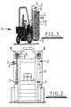
- an exemplary load handling vehicle is shown in the form of a forklift truck 1.
- a forklift truck 1 At the front of the truck there is a pair of laterally spaced, vertically extending mast assemblies 2 on which a forklift carriage 3 and the load L is raised or lowered with respect to the rest of the vehicle.
- Each mast assembly 2 comprises a hydraulic cylinder jack 4 for raising and lowering the carriage 3.
- the jack 4 is connected at one end to the vehicle structure and at a second end to a sheave 5 and is supplied with pressurised hydraulic fluid via a flow line and pump (not shown) that are managed by a lifting jack control circuit (not shown).
- Associated with each mast assembly 2 are three parallel, laterally spaced lifting chains 6, each of which is trained over a respective sheave 5 (or pulley) at the upper end of the mast assembly 2 such that the two ends 6a, 6b of the chain hang downwardly.
- a first end 6a of each lifting chain 6 is connected to the forklift carriage 3 by an anchor assembly 7 (for clarity only one assembly is shown in figure 2) and the second end 6b is fixed to a stationary structure on the truck.
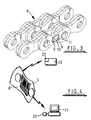
- each of the chains 6 has a particular chain link 8 that is fitted with a sensor unit S comprising strain gauges and associated electrical circuitry 9, a data storage device 10 comprising at least a memory chip, a clock, and a transceiver 11.
- the output of the strain gauge circuit 9 is an analogue electrical signal that is proportional to the elongation of the chain link 8 as a result of loading. The signal is therefore indicative of the load applied to the chain 6 at any point in time.
- the output signal of the strain gauge circuit 9 is converted into digital data ready for storage and/or processing and is transmitted to the data storage device 10.
- the sensor unit S is supplemented with a processor and appropriate software an amount of analysis of the data may be performed before it is then passed to the transceiver 11 for transmission to a remote transceiver 20 that is connected to a nearby computer 21 or a hand-held data capture unit 22.
- the data may be transmitted directly to the receiver without any analysis in the sensor unit S.
- the computer 21 may be in the form of a stand-alone PC with appropriate analysis software or may be a computer that is connected in a local or wide area network.
- the forklift truck may optionally be fitted with additional means to detect and transmit other information to the processor.
- a carriage height transducer 25 such as a linear potentiometer or one or more microswitches is positioned on a stationary part of the truck frame such that relative movement of the mast assembly can be monitored. This generates an output signal that is indicative of the vertical height of the carriage 3 (and therefore the load) relative to the rest of the mast assembly 2 of the truck.
- a bar code 26 reader is present on the front of the lifting carriage 3 or any other suitable position on the truck and is configured to read bar code information affixed to the load L that is being transported and bar code information disposed in physical proximity to the storage area from which or to which the load L is transported.
- the bar code on the load L carries unique identification code data relating to that load such as, for example, the part number, order number, or the mass of the individual items that make up the load.
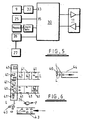
- the sensor unit S has the same components referred to above but is supplemented with a processor chip 30 and a receiver 31.
- the processor 30 is pre-loaded with data relating to the type of chain being analysed such as, for example, its type, length, certification and service history to date. This data may be pre-programmed into the processor 30 before the chain is fitted to the vehicle, may be entered with the sensor unit S and chain in-situ by means of a keypad temporarily connected to the sensor unit or may be entered remotely and transmitted from the transceiver 20 of the computer 21 or the hand-held data capture unit 22 to the sensor unit transceiver 11.
- the analogue output signal of the strain gauge circuit 9 is converted into digital data by an analogue to digital converter 32 and is passed to a data input port 33 of processor 30 along with a clock signal 34.
- the output signal of the carriage height transducer 25 is converted into digital data and is passed to another data input port 35 of the processor 30.
- the data scanned in from the bar code reader 26 is transmitted directly to the processor 30.
- the bar code reader 26 is connected to the audio signal generator 27 that is mounted on the truck near the driving position and generates a signal that instructs the signal generator 27 to emit an audio feedback signal to the truck driver when the bar code is read successfully.
- the processor performs some analysis on the stored data without the need to download it first.
- the processed or semi-processed data is downloaded in the manner described above. Downloading of the data may be achieved by using a wire connection or by wireless transmission. (e.g. infra-red or radio-wave).
- software can be used to process and analyse the information in a number of ways to assess the chain condition and to determine whether the chain needs servicing or replacing.
- the data can be analysed, for example, to determine the average number of hours that the chain has been used in a particular range of load magnitudes. This information is more meaningful and useful to a truck manufacturer, owner or lessor than a simple indication of how long the truck has been used. This is because for a significant proportion of the time in service the truck is usually not carrying any load.
- the data can be analysed to determine the number of times the load has exceeded a predetermined threshold for a given carriage height and/or the absolute value of those loads. This enables the lessor to determine how many times the recommended chain load has been exceeded and the impact this has on the risk of chain failure. Moreover, the lessor is able to determine whether the truck has been used to carry loads in excess of an agreed limit and therefore whether the terms of the lease have been broken. In that event the lessee of the truck may be liable for any damage to the truck. '
- the service conditions of the chain can be analysed, for example, by applying Miner's Rule to the data collected so as to predict the remaining life span of the chain. This analysis involves the calculation of the fractional contribution to fatigue damage at each load level (and therefore stress level) in the load spectrum.
- n 1 is the number of load cycles at load magnitude S 1 and the expected life span of the chain (when new) is N 1 cycles
- the fractional contribution to chain fatigue damage at load S 1 is n 1 /N 1 .
- the work conditions of the chains are monitored remotely during the use of the truck by means of a computer connected to a local or wide area network.
- the data stored in the memory of the sensor unit processor 30 fixed to the chain is transmitted at periodic intervals to the transceiver 20 that is connected into the computer network.
- the data is analysed by a software routine running on the computer network so as to generate meaningful results. As described above at least some of the analysis or calculations may be performed in a processor 30 that forms part of the sensor unit S attached to the chain (as described above).
- the stored data may be downloaded at periodic intervals to a hand-held data capture device 22 containing the necessary memory, processing capacity and software programs to analyse the data and a display to convey the information to the user.
- the device may receive the data by wireless communication as before. If necessary the hand-held unit 22 may be plugged into a computer system for further analysis of the data.
- an appropriate signal may be generated by the processor 30. This signal may be used to drive an audio or visual alarm to the truck driver or may control a cut-out circuit that is used disable the drive of the vehicle. Alternatively, the processing routine may calculate a threshold load magnitude for each height at which the carriage 3 may be disposed.
- the carriage height measurement data is compared to a threshold value for that load and if the threshold is exceeded or equalled a disable signal is sent by the processor 30 to the lifting jack control circuit so as to lower the height of the carriage 2 by retracting the jacks 4 or to disable further extension of the jacks 4.
- each chain has a sensor unit S of the kind described above with reference to figures 3 to 5 including a data storage device 10 and a transceiver 11. At least one of the units S has a processor 30.
- the output data from the strain gauge circuit 9 in each sensor unit S is representative of the load carried by each chain and is exchanged by the transceivers 11 of the sensor units S so that a real time comparison of the load carried by each chain 6 can be made by the processor 30. If this comparison shows a discrepancy between the chain tensions above a certain predetermined value an output signal is generated by the processor 30 to indicate that the tension of a particular chain requires adjustment.
- the bar code reader 26 (or other data reader) on the truck is used to read the bar code data (or other data) applied to the loads.
- a first bar code 40 is affixed to each load L or to a pallet on which that load is supported.
- a second bar code 41 is affixed to each storage location 42 in the warehouse.
- the data carried by the first bar code 40 may be coded information such as the load type, the mass of each individual part making up the load, part number and order number.
- a memory associated with the processor 30 is pre-programmed with a look-up table containing the weight of each individual item that might be stored in the warehouse. Once the bar code data is received by the processor 30 it can be processed and stored in an appropriate memory location so as to provide a record of the load being handled.
- the load sensor unit S measures the magnitude of the load in the manner described above and the data is passed to the processor 30 which uses the look-up table to identify the weight per item of the load type that has been read from the bar code. The processor 30 then calculates the number of items making up that load from the measured load magnitude and this value is stored.
- the truck transports the load L to an appropriate storage location 42 of the warehouse where it is unloaded.
- the bar code reader 26 is used as before to scan in the second bar code 41 associated with the storage location 42 where the load L has been stored and the data is again passed to the processor 30 for processing and is stored in an appropriate memory location to provide a record of the storage location of the load L.
- the same operation is used when a load is collected by the truck from a storage location 42 and distributed to an appropriate outgoing goods section 44 of the warehouse or to an alternative storage location 42.
- the collected information is used as part of an inventory record to monitor the movement of stock by the forklift truck.
- the processed data in the memory location is transmitted via a local or wide area network to a central mainframe database of a company concerned whereupon the information may be collated with similar information received from other warehouses. The collected information is then used in the management of stock control and purchasing.
- the sensor unit S is disposed in the anchor assembly 7.
- An example embodiment is shown in figure 7 in which a single sensor unit S is shown attached to an anchor assembly 7 of the chains 6.
- the final links of the chains 6 are connected to an anchor member 7a by means of a transverse pin 50.
- the anchor member 7a terminates in a generally cylindrical threaded end 51 that passes through an aperture 52 in a substantially horizontal web 53 integral to the lifting carriage 3.
- the threaded end 51 of the anchor member 7a is secured in place by means of a nut 54 that is threadedly engaged thereto.
- the nut 54 bears against the horizontal web 53 and prevents the anchor member passing through the aperture 52.
- the sensor unit S is disposed between the nut 54 and the web 53.
- the sensor unit S comprises a load ring 60 that is disposed coaxially with the threaded end of the anchor member 7a and is retained in a plastics housing 61 with steel top and bottom end caps 62, 63.
- One side of the housing 61 is configured to define a recess 64 in which the data storage device 10 and a battery (not shown) are to be located.
- a cover plate 65 seals the recess 64 from the surrounding environment.
- the load ring 60 is fitted with a strain gauge 66 that is connected by wire to the data storage device 10. When the chain is under load the threaded end 51 of the anchor member 7a is pulled upwardly towards the web 53.
- This action serves to compress the load ring 60 and end caps 62, 63 between the web and the nut 54.
- the strain gauge 66 serves to generate a signal representative of the degree of compression of the load ring 60 and therefore of the magnitude of the load L carried by the truck.
- the load monitoring system of the present invention has application to any type of load handling device in which a chain or other load bearing elongate flexible element is used (e.g. a belt or a cable) as part of a load conveying mechanism.
- a chain or other elongate load-bearing flexible element
- the system has application in other environments where a chain (or other elongate load-bearing flexible element) is used as part of a load conveyor mechanism.
- the system may be used with a chain drive of a roller-coaster ride in which passenger carriages are conveyed uphill by a chain drive.
- the sensor unit is applied the chain and the collected data is used as before to predict the remaining fatigue life of the chain.
Landscapes
- Engineering & Computer Science (AREA)
- Physics & Mathematics (AREA)
- General Physics & Mathematics (AREA)
- Business, Economics & Management (AREA)
- Mechanical Engineering (AREA)
- Economics (AREA)
- Finance (AREA)
- Entrepreneurship & Innovation (AREA)
- Chemical & Material Sciences (AREA)
- Analytical Chemistry (AREA)
- Geology (AREA)
- Accounting & Taxation (AREA)
- Life Sciences & Earth Sciences (AREA)
- Development Economics (AREA)
- Computer Networks & Wireless Communication (AREA)
- Structural Engineering (AREA)
- Human Resources & Organizations (AREA)
- Marketing (AREA)
- Operations Research (AREA)
- Quality & Reliability (AREA)
- Strategic Management (AREA)
- Tourism & Hospitality (AREA)
- General Business, Economics & Management (AREA)
- Theoretical Computer Science (AREA)
- Forklifts And Lifting Vehicles (AREA)
- Warehouses Or Storage Devices (AREA)
Claims (14)
- Vorrichtung zum Bestimmen der relativen Belastungen auf mehreren tragenden länglichen flexiblen Elementen (6) eines mobilen Lastenfbrderers (1), die mehrere längliche flexible Elemente (6) und Anker (7) für dieselben umfaßt, um die Elemente an dem Förderer zu befestigen, dadurch gekennzeichnet, daß ein an jedem Element oder Anker befestigter Wandler (S), um eine Ausgabe zu erzeugen, welche die auf ein entsprechendes Element (6) ausgeübte Belastung (L) repräsentiert, Mittel (30) zum Vergleichen der Belastungen und Mittel (30) zum Erzeugen eines Ausgabesignals, das eine ungleiche Belastung zwischen den Elementen anzeigt, bereitgestellt werden.
- Vorrichtung nach Anspruch 1 die ferner Mittel (5, 30) zum Berechnen des absoluten Werts der Belastung zu einem bestimmten Zeitpunkt umfaßt.
- Vorrichtung nach Anspruch 1 oder 2, die ferner Mittel (30) zum Berechnen der Zahl von Belastungszyklen über einem vorher festgelegten Belastungswert umfaßt.
- Vorrichtung nach einem der Ansprüche 1 bis 3, die ferner Mittel (30) zum Lesen von an den Lasten angebrachten codierten Daten umfaßt, wobei solche Daten Informationen, wie beispielsweise eine Lastenidentifikation und die Zahl von Artikeln, in einer bestimmten Last, einschließen.
- Vorrichtung nach einem der Ansprüche 1 bis 4, die ferner Mittel (30) zum Berechnen des kumulativen Ermüdungsschadens an der Kette umfaßt.
- Vorrichtung nach einem der Ansprüche 1 bis 5, die ferner ein Datenerfassungsgerät (10, 21, 22) umfaßt, wobei die Ausgabe des Wandlers (S) zu demselben übertragen werden kann.
- Vorrichtung nach Anspruch 6, wobei das Datenerfassungsgerät (21, 22) an einer von dem Wandler (S) entfernten Position angeordnet ist.
- Vorrichtung nach Anspruch 7, wobei das Datenerfassungsgerät dafür ausgelegt ist, in der Hand gehalten zu werden (22).
- Vorrichtung nach Anspruch 6, 7 oder 8, wobei das Datenerfassungsgerät (10, 21, 22) einen Prozessor zum Analysieren der empfangenen Daten einschließt.
- Vorrichtung nach einem der Ansprüche 6 bis 9, wobei die Datenübertragung von dem Wandler (S) zu dem Datenerfassungsgerät (10, 21, 22) durch drahtlose Kommunikation erfolgt.
- Vorrichtung nach einem der Ansprüche 6 bis 10, wobei das Datenerfassungsgerät (10, 21, 22) mit einem Rechnernetz verbunden werden kann, um einen Fernzugriff auf die darin enthaltenen Informationen zu ermöglichen.
- Vorrichtung nach einem der Ansprüche 6 bis 11, wobei die länglichen flexiblen Elemente (6) Ketten sind.
- Vorrichtung nach Anspruch 12, wobei der mobile Lastenförderer (1) ein. Gabelstapler ist.
- Verfahren zum Bestimmen der relativen Belastungen auf mehreren tragenden länglichen flexiblen Elementen eines mobilen Lastenförderers, wobei die Elemente Anker, um sie an dem Lastenforderer zu befestigen, und einen an jedem Element oder Anker befestigten Wandler, um ein Signal zu erzeugen, das die auf ein entsprechendes Element ausgeübte Belastung repräsentiert, haben, dadurch gekennzeichnet, daß das Verfahren den Schritt umfaßt, den durch die Signale repräsentierten Belastungswert zu vergleichen und ein Ausgabesignal zu erzeugen, das die ungleiche Belastung zwischen den Ketten anzeigt.
Applications Claiming Priority (5)
| Application Number | Priority Date | Filing Date | Title |
|---|---|---|---|
| GB0104489A GB0104489D0 (en) | 2001-02-23 | 2001-02-23 | Method and apparatus for monitoring the use and condition of a chain in a forklift |
| GB0104489 | 2001-02-23 | ||
| GB0111893A GB0111893D0 (en) | 2001-05-16 | 2001-05-16 | A load monitoring and inventory management system for use with a load conveyor |
| GB0111893 | 2001-05-16 | ||
| PCT/GB2002/000660 WO2002068310A2 (en) | 2001-02-23 | 2002-02-13 | A load monitoring and inventory management system for use with a load conveyor |
Publications (2)
| Publication Number | Publication Date |
|---|---|
| EP1362003A2 EP1362003A2 (de) | 2003-11-19 |
| EP1362003B1 true EP1362003B1 (de) | 2006-04-19 |
Family
ID=26245750
Family Applications (1)
| Application Number | Title | Priority Date | Filing Date |
|---|---|---|---|
| EP02711091A Expired - Lifetime EP1362003B1 (de) | 2001-02-23 | 2002-02-13 | Belastungs-überwachungssystem für fördergutträger |
Country Status (6)
| Country | Link |
|---|---|
| US (1) | US20040139806A1 (de) |
| EP (1) | EP1362003B1 (de) |
| JP (1) | JP2004521044A (de) |
| CA (1) | CA2438864A1 (de) |
| DE (1) | DE60210747T2 (de) |
| WO (1) | WO2002068310A2 (de) |
Cited By (2)
| Publication number | Priority date | Publication date | Assignee | Title |
|---|---|---|---|---|
| EP4501820A1 (de) * | 2023-08-03 | 2025-02-05 | Ashworth Bros., Inc. | System zur überwachung des betriebs eines förderbandes |
| US12545525B2 (en) | 2023-08-03 | 2026-02-10 | Ashworth Bros., Inc. | Conveyor belt operation monitoring system |
Families Citing this family (33)
| Publication number | Priority date | Publication date | Assignee | Title |
|---|---|---|---|---|
| US8073653B2 (en) | 2002-12-23 | 2011-12-06 | Caterpillar Inc. | Component life indicator |
| US7082845B2 (en) * | 2003-09-05 | 2006-08-01 | Weigh Point Incorporated | Device for leaf chain load cell |
| US7161254B1 (en) * | 2004-01-07 | 2007-01-09 | Trimble Navigation Ltd. | Methods and systems for harnessing electrical energy from ambient vibrational motion of a moving vehicle |
| US7770792B2 (en) * | 2004-06-23 | 2010-08-10 | Sap Ag | Methods and systems for managing stock transportation |
| US7669763B2 (en) * | 2004-06-23 | 2010-03-02 | Sap Ag | Methods and system for managing stock |
| GB0515176D0 (en) * | 2005-07-23 | 2005-08-31 | Renold Plc | Transmission chain monitoring system |
| US7444861B2 (en) * | 2005-11-22 | 2008-11-04 | Halliburton Energy Services, Inc. | Real time management system for slickline/wireline |
| US8381982B2 (en) * | 2005-12-03 | 2013-02-26 | Sky-Trax, Inc. | Method and apparatus for managing and controlling manned and automated utility vehicles |
| US20070239312A1 (en) * | 2006-04-10 | 2007-10-11 | Andersen Scott P | System and method for tracking inventory movement using a material handling device |
| US9984341B2 (en) | 2006-12-13 | 2018-05-29 | Crown Equipment Corporation | Information system for industrial vehicles including cyclical recurring vehicle information message |
| US10600256B2 (en) | 2006-12-13 | 2020-03-24 | Crown Equipment Corporation | Impact sensing usable with fleet management system |
| US10013815B2 (en) * | 2006-12-13 | 2018-07-03 | Crown Equipment Corporation | Information system for industrial vehicles |
| US11225404B2 (en) | 2006-12-13 | 2022-01-18 | Crown Equipment Corporation | Information system for industrial vehicles |
| EP2963596A1 (de) * | 2006-12-13 | 2016-01-06 | Crown Equipment Corporation | Flottenverwaltungssystem |
| DE102007035947A1 (de) * | 2007-07-30 | 2009-02-12 | Soehnle Professional Gmbh & Co. Kg | Anordnung zur Ermittlung einer an einem Zugmittel angreifenden Kraft |
| GB0719804D0 (en) * | 2007-09-29 | 2007-11-21 | Renold Plc | Transmission chain wear monitoring |
| US8565913B2 (en) * | 2008-02-01 | 2013-10-22 | Sky-Trax, Inc. | Apparatus and method for asset tracking |
| US7992686B2 (en) * | 2008-07-10 | 2011-08-09 | The Raymond Corporation | Pallet counter for lift truck |
| RU2517334C2 (ru) | 2009-08-12 | 2014-05-27 | КРАУН ЭКВАЙПМЕНТ КОРПОРЕЙШН, Корпорация штата Огайо | Информационная система для промышленных машин |
| WO2011028649A2 (en) | 2009-09-01 | 2011-03-10 | Crown Equipment Corporation | Information system for industrial vehicles including cyclical recurring vehicle information message |
| US8387777B2 (en) | 2009-10-06 | 2013-03-05 | Ecolab Usa Inc. | Conveyor chain tension monitor |
| US8191703B2 (en) | 2010-02-18 | 2012-06-05 | Ecolab Usa Inc. | Conveyor system monitoring and maintenance |
| EP2643792A4 (de) | 2010-11-18 | 2015-09-02 | Sky Trax Inc | Lastverfolgung mit lastidentifizierungsmarkierungen und räumlicher unterscheidung |
| CA2826440C (en) | 2011-02-16 | 2019-02-26 | Crown Equipment Corporation | Materials handling vehicle estimating a speed of a movable assembly from a lift motor speed |
| WO2012167819A1 (de) | 2011-06-07 | 2012-12-13 | Siemens Aktiengesellschaft | Verfahren zur ermittlung einer restlebensdauer einer maschinenkomponente und computerprogramm zur durchführung des verfahrens |
| ITPI20130036A1 (it) * | 2013-05-06 | 2014-11-07 | Newtecnik S R L | Un dispositivo di pesatura applicabile magneticamente alla forca di un sollevatore con collegamento dati wireless |
| US9416652B2 (en) | 2013-08-08 | 2016-08-16 | Vetco Gray Inc. | Sensing magnetized portions of a wellhead system to monitor fatigue loading |
| CZ305386B6 (cs) * | 2013-09-18 | 2015-08-26 | Schenck Process S.R.O. | Zařízení pro optimalizaci a indikaci provozního napnutí nekončitého řetězového pásma |
| DE102015102556A1 (de) * | 2015-02-23 | 2016-08-25 | Mack Rides Gmbh & Co. Kg | Vorrichtung und Verfahren zur Erhöhung der Sicherheit von Achterbahnen und/oder Karussells |
| DE102018003386B4 (de) * | 2018-03-30 | 2021-04-15 | Harald Peters | Realgewichtsbasierendes Logistik-System |
| DE102019121497A1 (de) * | 2019-08-09 | 2021-02-11 | Jungheinrich Aktiengesellschaft | Flurförderzeug und Verfahren zur Überwachung eines Flurförderzeugs |
| EP4217122A4 (de) * | 2020-09-25 | 2024-11-27 | Schenck Process Australia Pty Limited | Verfahren zur abschätzung kumulativer schäden und ermüdungsfestigkeit einer schwingmaschine |
| KR102337099B1 (ko) * | 2021-10-19 | 2021-12-07 | 김대경 | 물품 재고 관리용 프레임모듈과 그 프레임모듈이 구성된 재고 관리 시스템 |
Family Cites Families (22)
| Publication number | Priority date | Publication date | Assignee | Title |
|---|---|---|---|---|
| US1528154A (en) * | 1924-05-31 | 1925-03-03 | Joseph S Dickson | Amusement device |
| USRE30262E (en) * | 1971-05-27 | 1980-04-29 | Lord Corporation | Compressive load carrying bearings |
| DE2504445C2 (de) * | 1975-02-04 | 1977-03-24 | Krueger & Co Kg | Vorrichtung zur ueberwachung des lastmomentes eines verstellbaren kranauslegers |
| GB1555598A (en) * | 1977-10-20 | 1979-11-14 | Pye Electronic Prod Ltd | Load measuring arrangements for fork lift trucks or the like |
| US4336589A (en) * | 1980-04-07 | 1982-06-22 | Rapistan Division, Lear Siegler, Inc. | Warehousing monitor and control system |
| US4511974A (en) * | 1981-02-04 | 1985-04-16 | Kabushiki Kaisha Toyoda Jidoshokki Seisakusho | Load condition indicating method and apparatus for forklift truck |
| US4656591A (en) * | 1983-04-18 | 1987-04-07 | Goody Products, Inc. | Order processing method and apparatus (II) |
| US4630227A (en) * | 1984-04-27 | 1986-12-16 | Hagenbuch Roy George Le | Apparatus and method for on-board measuring of the load carried by a truck body |
| US4949263A (en) * | 1987-06-01 | 1990-08-14 | Alert-O-Brake Systems Inc. | Load handling vehicle monitoring system |
| US5164905A (en) * | 1987-08-12 | 1992-11-17 | Hitachi, Ltd. | Production system with order of processing determination |
| JPH02163202A (ja) * | 1988-12-13 | 1990-06-22 | Nippon Yusoki Co Ltd | 無線式在庫管理システム |
| DE3942009C2 (de) * | 1989-12-20 | 1994-03-03 | Deutsche Aerospace | System zur Kontrolle und Überwachung der Verteilung von Gütern |
| GB2246199B (en) * | 1990-07-16 | 1994-02-09 | Hugh Michael Oppen Pratt | Load measuring device |
| US5461561A (en) * | 1991-09-10 | 1995-10-24 | Electronic Retailing Systems International Inc. | System for recognizing display devices |
| JP2682951B2 (ja) * | 1993-10-12 | 1997-11-26 | 住友建機株式会社 | ジブ起伏ロープの寿命判定装置 |
| JP2748836B2 (ja) * | 1993-12-16 | 1998-05-13 | 日本鋼管株式会社 | クレーン用ワイヤーロープの寿命予測方法及びその装置 |
| US5671362A (en) * | 1995-04-04 | 1997-09-23 | Cowe; Alan B. | Materials monitoring systems, materials management systems and related methods |
| DE19610483A1 (de) * | 1996-03-16 | 1997-09-18 | Wagner Foerdertechnik | Betriebsdatenerfassungsgerät für ein Flurförderzeug |
| US5824963A (en) * | 1997-03-04 | 1998-10-20 | Gagetek Company | Lifting device employing a weight integrative weighing system |
| US6148291A (en) * | 1998-01-26 | 2000-11-14 | K & T Of Lorain, Ltd. | Container and inventory monitoring methods and systems |
| US6898988B2 (en) * | 2002-01-31 | 2005-05-31 | Autoliv Asp, Inc. | Integrated load cell system |
| US7026557B2 (en) * | 2003-10-30 | 2006-04-11 | Mettler-Toledo | Apparatus and method for weighting objects on a fork lift truck |
-
2002
- 2002-02-13 EP EP02711091A patent/EP1362003B1/de not_active Expired - Lifetime
- 2002-02-13 DE DE60210747T patent/DE60210747T2/de not_active Expired - Lifetime
- 2002-02-13 WO PCT/GB2002/000660 patent/WO2002068310A2/en not_active Ceased
- 2002-02-13 US US10/468,970 patent/US20040139806A1/en not_active Abandoned
- 2002-02-13 CA CA002438864A patent/CA2438864A1/en not_active Abandoned
- 2002-02-13 JP JP2002567837A patent/JP2004521044A/ja active Pending
Cited By (3)
| Publication number | Priority date | Publication date | Assignee | Title |
|---|---|---|---|---|
| EP4501820A1 (de) * | 2023-08-03 | 2025-02-05 | Ashworth Bros., Inc. | System zur überwachung des betriebs eines förderbandes |
| US12404113B2 (en) | 2023-08-03 | 2025-09-02 | Ashworth Bros., Inc. | Conveyor belt operation monitoring system |
| US12545525B2 (en) | 2023-08-03 | 2026-02-10 | Ashworth Bros., Inc. | Conveyor belt operation monitoring system |
Also Published As
| Publication number | Publication date |
|---|---|
| WO2002068310A2 (en) | 2002-09-06 |
| US20040139806A1 (en) | 2004-07-22 |
| DE60210747D1 (de) | 2006-05-24 |
| EP1362003A2 (de) | 2003-11-19 |
| CA2438864A1 (en) | 2002-09-06 |
| DE60210747T2 (de) | 2007-04-12 |
| WO2002068310A3 (en) | 2002-12-19 |
| JP2004521044A (ja) | 2004-07-15 |
Similar Documents
| Publication | Publication Date | Title |
|---|---|---|
| EP1362003B1 (de) | Belastungs-überwachungssystem für fördergutträger | |
| CA2822159C (en) | Method in the check weighing of a weighing system and software product and arrangement in the check weighing of a weighing system and materials handling equipment | |
| CA1255797A (en) | Apparatus and method responsive to the on-board measuring of the load carried by a truck body | |
| EP1907810B1 (de) | Übertragungsketten-überwachungssystem | |
| AU650359B2 (en) | Load moment indicator system | |
| US6439341B1 (en) | Apparatus for monitoring loading of a lift | |
| EP3106423A1 (de) | Systeme und verfahren zur gewichtsermittlung und rückkopplungs-drehzahlregelung | |
| US9046409B2 (en) | Weighing scale for forklift for measuring weight of loads as they are lifted | |
| EP2143683A1 (de) | Palettenzähler für einen Gabelstapler | |
| US6865955B2 (en) | Conveyor diagnostic system | |
| US20220162048A1 (en) | Carrier for a Lifting Device, Lifting Device Provided Therewith and Method Therefor | |
| US4845648A (en) | Apparatus and method for on-board measuring of the load carried by a truck body | |
| CN111320082A (zh) | 确定货物重量的方法、装置及仓库管理方法 | |
| US6232566B1 (en) | Apparatus in a lifting device for reducing error in weight measurements | |
| MXPA06013238A (es) | Metodo de medicion con reduccion de fuerza para mecanismos de traccion, en particular mecanismos de impulsion por polea motriz para ascensores. | |
| EP4119426B1 (de) | Vorrichtung und verfahren zur überwachung des schmierungszustands eines lagers einer laufrolle eines fahrwerks eines raupenfahrzeugs | |
| DE19911642B4 (de) | Verfahren zur fortlaufenden Messung des Verschleißes aller Tragrollen in Gurtförderern | |
| EP3403980B1 (de) | Verfahren zur spannung eines lasttragenden elements eines aufzugssystems | |
| US12351436B2 (en) | Structural health monitoring system for material handling systems | |
| WO2000063805A1 (en) | Cargo loading and unloading systems | |
| CN221093304U (zh) | 一种箕斗称重检测装置 | |
| CN108726303A (zh) | 一种基于大数据的货梯缆索监测装置 | |
| CA1287888C (en) | Apparatus and method responsive to the on-board measuring of the load carried by a truck body | |
| CN108083047B (zh) | 一种基于导向轮轴应变的提升系统负载识别方法 | |
| CN113182207A (zh) | 一种运输称重平台的运行控制方法、系统、终端及介质 |
Legal Events
| Date | Code | Title | Description |
|---|---|---|---|
| PUAI | Public reference made under article 153(3) epc to a published international application that has entered the european phase |
Free format text: ORIGINAL CODE: 0009012 |
|
| 17P | Request for examination filed |
Effective date: 20030822 |
|
| AK | Designated contracting states |
Kind code of ref document: A2 Designated state(s): AT BE CH CY DE DK ES FI FR GB GR IE IT LI LU MC NL PT SE TR |
|
| AX | Request for extension of the european patent |
Extension state: AL LT LV MK RO SI |
|
| 17Q | First examination report despatched |
Effective date: 20041007 |
|
| RTI1 | Title (correction) |
Free format text: A LOAD MONITORING SYSTEM FOR USE WITH A LOAD CONVEYOR |
|
| GRAP | Despatch of communication of intention to grant a patent |
Free format text: ORIGINAL CODE: EPIDOSNIGR1 |
|
| GRAS | Grant fee paid |
Free format text: ORIGINAL CODE: EPIDOSNIGR3 |
|
| GRAA | (expected) grant |
Free format text: ORIGINAL CODE: 0009210 |
|
| AK | Designated contracting states |
Kind code of ref document: B1 Designated state(s): DE FR GB IT |
|
| PG25 | Lapsed in a contracting state [announced via postgrant information from national office to epo] |
Ref country code: IT Free format text: LAPSE BECAUSE OF FAILURE TO SUBMIT A TRANSLATION OF THE DESCRIPTION OR TO PAY THE FEE WITHIN THE PRESCRIBED TIME-LIMIT;WARNING: LAPSES OF ITALIAN PATENTS WITH EFFECTIVE DATE BEFORE 2007 MAY HAVE OCCURRED AT ANY TIME BEFORE 2007. THE CORRECT EFFECTIVE DATE MAY BE DIFFERENT FROM THE ONE RECORDED. Effective date: 20060419 |
|
| REG | Reference to a national code |
Ref country code: GB Ref legal event code: FG4D |
|
| REF | Corresponds to: |
Ref document number: 60210747 Country of ref document: DE Date of ref document: 20060524 Kind code of ref document: P |
|
| ET | Fr: translation filed | ||
| PLBE | No opposition filed within time limit |
Free format text: ORIGINAL CODE: 0009261 |
|
| STAA | Information on the status of an ep patent application or granted ep patent |
Free format text: STATUS: NO OPPOSITION FILED WITHIN TIME LIMIT |
|
| 26N | No opposition filed |
Effective date: 20070122 |
|
| PGFP | Annual fee paid to national office [announced via postgrant information from national office to epo] |
Ref country code: IT Payment date: 20090213 Year of fee payment: 8 |
|
| PGFP | Annual fee paid to national office [announced via postgrant information from national office to epo] |
Ref country code: FR Payment date: 20100223 Year of fee payment: 9 |
|
| PGFP | Annual fee paid to national office [announced via postgrant information from national office to epo] |
Ref country code: DE Payment date: 20100226 Year of fee payment: 9 |
|
| PG25 | Lapsed in a contracting state [announced via postgrant information from national office to epo] |
Ref country code: IT Free format text: LAPSE BECAUSE OF NON-PAYMENT OF DUE FEES Effective date: 20100213 |
|
| REG | Reference to a national code |
Ref country code: FR Ref legal event code: ST Effective date: 20111102 |
|
| REG | Reference to a national code |
Ref country code: DE Ref legal event code: R119 Ref document number: 60210747 Country of ref document: DE Effective date: 20110901 |
|
| PG25 | Lapsed in a contracting state [announced via postgrant information from national office to epo] |
Ref country code: FR Free format text: LAPSE BECAUSE OF NON-PAYMENT OF DUE FEES Effective date: 20110228 |
|
| PG25 | Lapsed in a contracting state [announced via postgrant information from national office to epo] |
Ref country code: DE Free format text: LAPSE BECAUSE OF NON-PAYMENT OF DUE FEES Effective date: 20110901 |
|
| PGFP | Annual fee paid to national office [announced via postgrant information from national office to epo] |
Ref country code: GB Payment date: 20170208 Year of fee payment: 16 |
|
| GBPC | Gb: european patent ceased through non-payment of renewal fee |
Effective date: 20180213 |
|
| PG25 | Lapsed in a contracting state [announced via postgrant information from national office to epo] |
Ref country code: GB Free format text: LAPSE BECAUSE OF NON-PAYMENT OF DUE FEES Effective date: 20180213 |