EP1361916B1 - Selektive, wasserstoffdurchlässige membranverbundstrukturen und brenngasprozessor unter verwendung derselben - Google Patents
Selektive, wasserstoffdurchlässige membranverbundstrukturen und brenngasprozessor unter verwendung derselben Download PDFInfo
- Publication number
- EP1361916B1 EP1361916B1 EP02704838A EP02704838A EP1361916B1 EP 1361916 B1 EP1361916 B1 EP 1361916B1 EP 02704838 A EP02704838 A EP 02704838A EP 02704838 A EP02704838 A EP 02704838A EP 1361916 B1 EP1361916 B1 EP 1361916B1
- Authority
- EP
- European Patent Office
- Prior art keywords
- hydrogen
- structures
- substrate
- filtering
- selectively permeable
- Prior art date
- Legal status (The legal status is an assumption and is not a legal conclusion. Google has not performed a legal analysis and makes no representation as to the accuracy of the status listed.)
- Expired - Lifetime
Links
- 229910052739 hydrogen Inorganic materials 0.000 title claims abstract description 114
- 239000001257 hydrogen Substances 0.000 title claims abstract description 113
- UFHFLCQGNIYNRP-UHFFFAOYSA-N Hydrogen Chemical compound [H][H] UFHFLCQGNIYNRP-UHFFFAOYSA-N 0.000 title claims abstract description 93
- 239000007789 gas Substances 0.000 title claims abstract description 46
- 239000002131 composite material Substances 0.000 title claims abstract description 19
- 239000012528 membrane Substances 0.000 title claims description 75
- 238000001914 filtration Methods 0.000 claims abstract description 67
- 239000000758 substrate Substances 0.000 claims abstract description 60
- KDLHZDBZIXYQEI-UHFFFAOYSA-N Palladium Chemical compound [Pd] KDLHZDBZIXYQEI-UHFFFAOYSA-N 0.000 claims abstract description 58
- 230000035699 permeability Effects 0.000 claims abstract description 15
- 238000006243 chemical reaction Methods 0.000 claims description 70
- PXHVJJICTQNCMI-UHFFFAOYSA-N Nickel Chemical compound [Ni] PXHVJJICTQNCMI-UHFFFAOYSA-N 0.000 claims description 44
- 229910052763 palladium Inorganic materials 0.000 claims description 28
- 229910052751 metal Inorganic materials 0.000 claims description 26
- 239000002184 metal Substances 0.000 claims description 26
- 239000000203 mixture Substances 0.000 claims description 22
- 239000003054 catalyst Substances 0.000 claims description 21
- 229910052759 nickel Inorganic materials 0.000 claims description 20
- 150000002431 hydrogen Chemical class 0.000 claims description 19
- 239000000463 material Substances 0.000 claims description 15
- XEEYBQQBJWHFJM-UHFFFAOYSA-N Iron Chemical compound [Fe] XEEYBQQBJWHFJM-UHFFFAOYSA-N 0.000 claims description 14
- 229910001055 inconels 600 Inorganic materials 0.000 claims description 14
- 239000011148 porous material Substances 0.000 claims description 13
- 239000000126 substance Substances 0.000 claims description 13
- 239000000843 powder Substances 0.000 claims description 12
- 229910000601 superalloy Inorganic materials 0.000 claims description 11
- CURLTUGMZLYLDI-UHFFFAOYSA-N Carbon dioxide Chemical compound O=C=O CURLTUGMZLYLDI-UHFFFAOYSA-N 0.000 claims description 10
- 229910045601 alloy Inorganic materials 0.000 claims description 10
- 239000000956 alloy Substances 0.000 claims description 10
- 229910002091 carbon monoxide Inorganic materials 0.000 claims description 10
- 238000010438 heat treatment Methods 0.000 claims description 10
- UGFAIRIUMAVXCW-UHFFFAOYSA-N Carbon monoxide Chemical compound [O+]#[C-] UGFAIRIUMAVXCW-UHFFFAOYSA-N 0.000 claims description 9
- 239000004332 silver Substances 0.000 claims description 9
- VYZAMTAEIAYCRO-UHFFFAOYSA-N Chromium Chemical compound [Cr] VYZAMTAEIAYCRO-UHFFFAOYSA-N 0.000 claims description 8
- 238000000746 purification Methods 0.000 claims description 8
- 229910052804 chromium Inorganic materials 0.000 claims description 7
- 239000011651 chromium Substances 0.000 claims description 7
- 230000005495 cold plasma Effects 0.000 claims description 7
- 239000008187 granular material Substances 0.000 claims description 7
- 229910052742 iron Inorganic materials 0.000 claims description 7
- 230000002787 reinforcement Effects 0.000 claims description 7
- 229910052709 silver Inorganic materials 0.000 claims description 7
- 238000002347 injection Methods 0.000 claims description 6
- 239000007924 injection Substances 0.000 claims description 6
- 230000004888 barrier function Effects 0.000 claims description 5
- 229910002092 carbon dioxide Inorganic materials 0.000 claims description 5
- 239000001569 carbon dioxide Substances 0.000 claims description 5
- 230000003750 conditioning effect Effects 0.000 claims description 5
- XLYOFNOQVPJJNP-UHFFFAOYSA-N water Substances O XLYOFNOQVPJJNP-UHFFFAOYSA-N 0.000 claims description 5
- 239000004020 conductor Substances 0.000 claims description 4
- 230000006835 compression Effects 0.000 claims description 2
- 238000007906 compression Methods 0.000 claims description 2
- 230000001419 dependent effect Effects 0.000 claims description 2
- 230000007935 neutral effect Effects 0.000 claims description 2
- 230000004044 response Effects 0.000 claims description 2
- 239000011248 coating agent Substances 0.000 claims 2
- 238000000576 coating method Methods 0.000 claims 2
- 210000003462 vein Anatomy 0.000 claims 1
- 229910001252 Pd alloy Inorganic materials 0.000 abstract description 9
- 238000005245 sintering Methods 0.000 abstract description 9
- 229910001026 inconel Inorganic materials 0.000 abstract description 7
- 239000007787 solid Substances 0.000 abstract description 4
- 229910001316 Ag alloy Inorganic materials 0.000 abstract description 3
- 230000006378 damage Effects 0.000 abstract description 3
- 239000010410 layer Substances 0.000 description 79
- 239000012159 carrier gas Substances 0.000 description 11
- BQCADISMDOOEFD-UHFFFAOYSA-N Silver Chemical compound [Ag] BQCADISMDOOEFD-UHFFFAOYSA-N 0.000 description 10
- 239000000446 fuel Substances 0.000 description 8
- 239000002737 fuel gas Substances 0.000 description 8
- 208000031968 Cadaver Diseases 0.000 description 7
- 239000012535 impurity Substances 0.000 description 7
- VNWKTOKETHGBQD-UHFFFAOYSA-N methane Chemical compound C VNWKTOKETHGBQD-UHFFFAOYSA-N 0.000 description 6
- 239000000919 ceramic Substances 0.000 description 5
- 238000010586 diagram Methods 0.000 description 5
- 239000002245 particle Substances 0.000 description 5
- IJGRMHOSHXDMSA-UHFFFAOYSA-N Atomic nitrogen Chemical compound N#N IJGRMHOSHXDMSA-UHFFFAOYSA-N 0.000 description 4
- ATUOYWHBWRKTHZ-UHFFFAOYSA-N Propane Chemical compound CCC ATUOYWHBWRKTHZ-UHFFFAOYSA-N 0.000 description 4
- VYPSYNLAJGMNEJ-UHFFFAOYSA-N Silicium dioxide Chemical compound O=[Si]=O VYPSYNLAJGMNEJ-UHFFFAOYSA-N 0.000 description 4
- 238000006356 dehydrogenation reaction Methods 0.000 description 4
- 238000000151 deposition Methods 0.000 description 4
- 230000006870 function Effects 0.000 description 4
- 238000000034 method Methods 0.000 description 4
- 229910052799 carbon Inorganic materials 0.000 description 3
- 230000000295 complement effect Effects 0.000 description 3
- 238000006073 displacement reaction Methods 0.000 description 3
- 230000008030 elimination Effects 0.000 description 3
- 238000003379 elimination reaction Methods 0.000 description 3
- 239000008246 gaseous mixture Substances 0.000 description 3
- 229930195733 hydrocarbon Natural products 0.000 description 3
- 150000002430 hydrocarbons Chemical class 0.000 description 3
- 238000004519 manufacturing process Methods 0.000 description 3
- 150000002739 metals Chemical class 0.000 description 3
- 238000005192 partition Methods 0.000 description 3
- 238000011084 recovery Methods 0.000 description 3
- 239000010935 stainless steel Substances 0.000 description 3
- 229910001220 stainless steel Inorganic materials 0.000 description 3
- 238000011144 upstream manufacturing Methods 0.000 description 3
- OKTJSMMVPCPJKN-UHFFFAOYSA-N Carbon Chemical compound [C] OKTJSMMVPCPJKN-UHFFFAOYSA-N 0.000 description 2
- 239000004215 Carbon black (E152) Substances 0.000 description 2
- XDTMQSROBMDMFD-UHFFFAOYSA-N Cyclohexane Chemical compound C1CCCCC1 XDTMQSROBMDMFD-UHFFFAOYSA-N 0.000 description 2
- OTMSDBZUPAUEDD-UHFFFAOYSA-N Ethane Chemical compound CC OTMSDBZUPAUEDD-UHFFFAOYSA-N 0.000 description 2
- LFQSCWFLJHTTHZ-UHFFFAOYSA-N Ethanol Chemical compound CCO LFQSCWFLJHTTHZ-UHFFFAOYSA-N 0.000 description 2
- YNQLUTRBYVCPMQ-UHFFFAOYSA-N Ethylbenzene Chemical compound CCC1=CC=CC=C1 YNQLUTRBYVCPMQ-UHFFFAOYSA-N 0.000 description 2
- 229910000990 Ni alloy Inorganic materials 0.000 description 2
- 229910000831 Steel Inorganic materials 0.000 description 2
- 230000009471 action Effects 0.000 description 2
- PNEYBMLMFCGWSK-UHFFFAOYSA-N aluminium oxide Inorganic materials [O-2].[O-2].[O-2].[Al+3].[Al+3] PNEYBMLMFCGWSK-UHFFFAOYSA-N 0.000 description 2
- 230000008901 benefit Effects 0.000 description 2
- 238000006555 catalytic reaction Methods 0.000 description 2
- 239000000470 constituent Substances 0.000 description 2
- 230000007423 decrease Effects 0.000 description 2
- 230000008021 deposition Effects 0.000 description 2
- 238000009826 distribution Methods 0.000 description 2
- 230000000694 effects Effects 0.000 description 2
- 238000001033 granulometry Methods 0.000 description 2
- 230000006872 improvement Effects 0.000 description 2
- 230000004048 modification Effects 0.000 description 2
- 238000012986 modification Methods 0.000 description 2
- 229910052757 nitrogen Inorganic materials 0.000 description 2
- 238000005240 physical vapour deposition Methods 0.000 description 2
- 239000001294 propane Substances 0.000 description 2
- 238000002407 reforming Methods 0.000 description 2
- 230000002441 reversible effect Effects 0.000 description 2
- 230000035939 shock Effects 0.000 description 2
- 239000000377 silicon dioxide Substances 0.000 description 2
- 239000010959 steel Substances 0.000 description 2
- 239000010963 304 stainless steel Substances 0.000 description 1
- QPLDLSVMHZLSFG-UHFFFAOYSA-N Copper oxide Chemical class [Cu]=O QPLDLSVMHZLSFG-UHFFFAOYSA-N 0.000 description 1
- 229910001111 Fine metal Inorganic materials 0.000 description 1
- YZCKVEUIGOORGS-UHFFFAOYSA-N Hydrogen atom Chemical compound [H] YZCKVEUIGOORGS-UHFFFAOYSA-N 0.000 description 1
- PWHULOQIROXLJO-UHFFFAOYSA-N Manganese Chemical compound [Mn] PWHULOQIROXLJO-UHFFFAOYSA-N 0.000 description 1
- KJTLSVCANCCWHF-UHFFFAOYSA-N Ruthenium Chemical compound [Ru] KJTLSVCANCCWHF-UHFFFAOYSA-N 0.000 description 1
- 229910000589 SAE 304 stainless steel Inorganic materials 0.000 description 1
- HCHKCACWOHOZIP-UHFFFAOYSA-N Zinc Chemical compound [Zn] HCHKCACWOHOZIP-UHFFFAOYSA-N 0.000 description 1
- 238000005054 agglomeration Methods 0.000 description 1
- 230000002776 aggregation Effects 0.000 description 1
- 150000001298 alcohols Chemical class 0.000 description 1
- 239000011324 bead Substances 0.000 description 1
- 230000009286 beneficial effect Effects 0.000 description 1
- 230000015572 biosynthetic process Effects 0.000 description 1
- 230000003197 catalytic effect Effects 0.000 description 1
- UOUJSJZBMCDAEU-UHFFFAOYSA-N chromium(3+);oxygen(2-) Chemical class [O-2].[O-2].[O-2].[Cr+3].[Cr+3] UOUJSJZBMCDAEU-UHFFFAOYSA-N 0.000 description 1
- 239000000567 combustion gas Substances 0.000 description 1
- 230000008602 contraction Effects 0.000 description 1
- 230000007547 defect Effects 0.000 description 1
- 238000009792 diffusion process Methods 0.000 description 1
- 230000005684 electric field Effects 0.000 description 1
- 238000005485 electric heating Methods 0.000 description 1
- 238000005868 electrolysis reaction Methods 0.000 description 1
- 239000000284 extract Substances 0.000 description 1
- 239000000835 fiber Substances 0.000 description 1
- 230000004907 flux Effects 0.000 description 1
- 239000011521 glass Substances 0.000 description 1
- 229910000856 hastalloy Inorganic materials 0.000 description 1
- 238000009413 insulation Methods 0.000 description 1
- 239000011229 interlayer Substances 0.000 description 1
- UQSXHKLRYXJYBZ-UHFFFAOYSA-N iron oxide Inorganic materials [Fe]=O UQSXHKLRYXJYBZ-UHFFFAOYSA-N 0.000 description 1
- 235000013980 iron oxide Nutrition 0.000 description 1
- VBMVTYDPPZVILR-UHFFFAOYSA-N iron(2+);oxygen(2-) Chemical class [O-2].[Fe+2] VBMVTYDPPZVILR-UHFFFAOYSA-N 0.000 description 1
- 230000001788 irregular Effects 0.000 description 1
- 229910052748 manganese Inorganic materials 0.000 description 1
- 239000011572 manganese Substances 0.000 description 1
- 230000008018 melting Effects 0.000 description 1
- 238000002844 melting Methods 0.000 description 1
- 239000011785 micronutrient Substances 0.000 description 1
- 235000013369 micronutrients Nutrition 0.000 description 1
- 239000011490 mineral wool Substances 0.000 description 1
- 238000007254 oxidation reaction Methods 0.000 description 1
- 239000008188 pellet Substances 0.000 description 1
- 230000000737 periodic effect Effects 0.000 description 1
- 230000002688 persistence Effects 0.000 description 1
- 239000002574 poison Substances 0.000 description 1
- 231100000614 poison Toxicity 0.000 description 1
- 230000008569 process Effects 0.000 description 1
- 239000011541 reaction mixture Substances 0.000 description 1
- 230000001105 regulatory effect Effects 0.000 description 1
- 229910052707 ruthenium Inorganic materials 0.000 description 1
- 239000000243 solution Substances 0.000 description 1
- 238000003786 synthesis reaction Methods 0.000 description 1
- 230000009466 transformation Effects 0.000 description 1
- 238000007738 vacuum evaporation Methods 0.000 description 1
- 210000000264 venule Anatomy 0.000 description 1
- 238000003466 welding Methods 0.000 description 1
- 229910052725 zinc Inorganic materials 0.000 description 1
- 239000011701 zinc Substances 0.000 description 1
Images
Classifications
-
- B—PERFORMING OPERATIONS; TRANSPORTING
- B01—PHYSICAL OR CHEMICAL PROCESSES OR APPARATUS IN GENERAL
- B01D—SEPARATION
- B01D69/00—Semi-permeable membranes for separation processes or apparatus characterised by their form, structure or properties; Manufacturing processes specially adapted therefor
- B01D69/14—Dynamic membranes
- B01D69/141—Heterogeneous membranes, e.g. containing dispersed material; Mixed matrix membranes
-
- B—PERFORMING OPERATIONS; TRANSPORTING
- B01—PHYSICAL OR CHEMICAL PROCESSES OR APPARATUS IN GENERAL
- B01D—SEPARATION
- B01D53/00—Separation of gases or vapours; Recovering vapours of volatile solvents from gases; Chemical or biological purification of waste gases, e.g. engine exhaust gases, smoke, fumes, flue gases, aerosols
- B01D53/22—Separation of gases or vapours; Recovering vapours of volatile solvents from gases; Chemical or biological purification of waste gases, e.g. engine exhaust gases, smoke, fumes, flue gases, aerosols by diffusion
- B01D53/228—Separation of gases or vapours; Recovering vapours of volatile solvents from gases; Chemical or biological purification of waste gases, e.g. engine exhaust gases, smoke, fumes, flue gases, aerosols by diffusion characterised by specific membranes
-
- B—PERFORMING OPERATIONS; TRANSPORTING
- B01—PHYSICAL OR CHEMICAL PROCESSES OR APPARATUS IN GENERAL
- B01D—SEPARATION
- B01D53/00—Separation of gases or vapours; Recovering vapours of volatile solvents from gases; Chemical or biological purification of waste gases, e.g. engine exhaust gases, smoke, fumes, flue gases, aerosols
- B01D53/22—Separation of gases or vapours; Recovering vapours of volatile solvents from gases; Chemical or biological purification of waste gases, e.g. engine exhaust gases, smoke, fumes, flue gases, aerosols by diffusion
- B01D53/229—Integrated processes (Diffusion and at least one other process, e.g. adsorption, absorption)
-
- B—PERFORMING OPERATIONS; TRANSPORTING
- B01—PHYSICAL OR CHEMICAL PROCESSES OR APPARATUS IN GENERAL
- B01D—SEPARATION
- B01D63/00—Apparatus in general for separation processes using semi-permeable membranes
- B01D63/02—Hollow fibre modules
-
- B—PERFORMING OPERATIONS; TRANSPORTING
- B01—PHYSICAL OR CHEMICAL PROCESSES OR APPARATUS IN GENERAL
- B01D—SEPARATION
- B01D67/00—Processes specially adapted for manufacturing semi-permeable membranes for separation processes or apparatus
- B01D67/0039—Inorganic membrane manufacture
- B01D67/0041—Inorganic membrane manufacture by agglomeration of particles in the dry state
- B01D67/00411—Inorganic membrane manufacture by agglomeration of particles in the dry state by sintering
-
- B—PERFORMING OPERATIONS; TRANSPORTING
- B01—PHYSICAL OR CHEMICAL PROCESSES OR APPARATUS IN GENERAL
- B01D—SEPARATION
- B01D69/00—Semi-permeable membranes for separation processes or apparatus characterised by their form, structure or properties; Manufacturing processes specially adapted therefor
- B01D69/04—Tubular membranes
-
- B—PERFORMING OPERATIONS; TRANSPORTING
- B01—PHYSICAL OR CHEMICAL PROCESSES OR APPARATUS IN GENERAL
- B01D—SEPARATION
- B01D71/00—Semi-permeable membranes for separation processes or apparatus characterised by the material; Manufacturing processes specially adapted therefor
- B01D71/02—Inorganic material
- B01D71/022—Metals
- B01D71/0223—Group 8, 9 or 10 metals
- B01D71/02231—Palladium
-
- B—PERFORMING OPERATIONS; TRANSPORTING
- B01—PHYSICAL OR CHEMICAL PROCESSES OR APPARATUS IN GENERAL
- B01J—CHEMICAL OR PHYSICAL PROCESSES, e.g. CATALYSIS OR COLLOID CHEMISTRY; THEIR RELEVANT APPARATUS
- B01J19/00—Chemical, physical or physico-chemical processes in general; Their relevant apparatus
- B01J19/08—Processes employing the direct application of electric or wave energy, or particle radiation; Apparatus therefor
- B01J19/087—Processes employing the direct application of electric or wave energy, or particle radiation; Apparatus therefor employing electric or magnetic energy
- B01J19/088—Processes employing the direct application of electric or wave energy, or particle radiation; Apparatus therefor employing electric or magnetic energy giving rise to electric discharges
-
- C—CHEMISTRY; METALLURGY
- C01—INORGANIC CHEMISTRY
- C01B—NON-METALLIC ELEMENTS; COMPOUNDS THEREOF; METALLOIDS OR COMPOUNDS THEREOF NOT COVERED BY SUBCLASS C01C
- C01B3/00—Hydrogen; Gaseous mixtures containing hydrogen; Separation of hydrogen from mixtures containing it; Purification of hydrogen
- C01B3/02—Production of hydrogen or of gaseous mixtures containing a substantial proportion of hydrogen
- C01B3/32—Production of hydrogen or of gaseous mixtures containing a substantial proportion of hydrogen by reaction of gaseous or liquid organic compounds with gasifying agents, e.g. water, carbon dioxide, air
- C01B3/34—Production of hydrogen or of gaseous mixtures containing a substantial proportion of hydrogen by reaction of gaseous or liquid organic compounds with gasifying agents, e.g. water, carbon dioxide, air by reaction of hydrocarbons with gasifying agents
- C01B3/342—Production of hydrogen or of gaseous mixtures containing a substantial proportion of hydrogen by reaction of gaseous or liquid organic compounds with gasifying agents, e.g. water, carbon dioxide, air by reaction of hydrocarbons with gasifying agents with the aid of electrical means, electromagnetic or mechanical vibrations, or particle radiations
-
- C—CHEMISTRY; METALLURGY
- C01—INORGANIC CHEMISTRY
- C01B—NON-METALLIC ELEMENTS; COMPOUNDS THEREOF; METALLOIDS OR COMPOUNDS THEREOF NOT COVERED BY SUBCLASS C01C
- C01B3/00—Hydrogen; Gaseous mixtures containing hydrogen; Separation of hydrogen from mixtures containing it; Purification of hydrogen
- C01B3/50—Separation of hydrogen or hydrogen containing gases from gaseous mixtures, e.g. purification
- C01B3/501—Separation of hydrogen or hydrogen containing gases from gaseous mixtures, e.g. purification by diffusion
-
- B—PERFORMING OPERATIONS; TRANSPORTING
- B01—PHYSICAL OR CHEMICAL PROCESSES OR APPARATUS IN GENERAL
- B01D—SEPARATION
- B01D2313/00—Details relating to membrane modules or apparatus
- B01D2313/22—Cooling or heating elements
-
- B—PERFORMING OPERATIONS; TRANSPORTING
- B01—PHYSICAL OR CHEMICAL PROCESSES OR APPARATUS IN GENERAL
- B01D—SEPARATION
- B01D2313/00—Details relating to membrane modules or apparatus
- B01D2313/42—Catalysts within the flow path
-
- B—PERFORMING OPERATIONS; TRANSPORTING
- B01—PHYSICAL OR CHEMICAL PROCESSES OR APPARATUS IN GENERAL
- B01D—SEPARATION
- B01D2319/00—Membrane assemblies within one housing
- B01D2319/04—Elements in parallel
-
- B—PERFORMING OPERATIONS; TRANSPORTING
- B01—PHYSICAL OR CHEMICAL PROCESSES OR APPARATUS IN GENERAL
- B01D—SEPARATION
- B01D2325/00—Details relating to properties of membranes
- B01D2325/02—Details relating to pores or porosity of the membranes
-
- B—PERFORMING OPERATIONS; TRANSPORTING
- B01—PHYSICAL OR CHEMICAL PROCESSES OR APPARATUS IN GENERAL
- B01D—SEPARATION
- B01D2325/00—Details relating to properties of membranes
- B01D2325/04—Characteristic thickness
-
- B—PERFORMING OPERATIONS; TRANSPORTING
- B01—PHYSICAL OR CHEMICAL PROCESSES OR APPARATUS IN GENERAL
- B01D—SEPARATION
- B01D2325/00—Details relating to properties of membranes
- B01D2325/22—Thermal or heat-resistance properties
-
- B—PERFORMING OPERATIONS; TRANSPORTING
- B01—PHYSICAL OR CHEMICAL PROCESSES OR APPARATUS IN GENERAL
- B01D—SEPARATION
- B01D2325/00—Details relating to properties of membranes
- B01D2325/24—Mechanical properties, e.g. strength
-
- B—PERFORMING OPERATIONS; TRANSPORTING
- B01—PHYSICAL OR CHEMICAL PROCESSES OR APPARATUS IN GENERAL
- B01J—CHEMICAL OR PHYSICAL PROCESSES, e.g. CATALYSIS OR COLLOID CHEMISTRY; THEIR RELEVANT APPARATUS
- B01J2219/00—Chemical, physical or physico-chemical processes in general; Their relevant apparatus
- B01J2219/08—Processes employing the direct application of electric or wave energy, or particle radiation; Apparatus therefor
- B01J2219/0803—Processes employing the direct application of electric or wave energy, or particle radiation; Apparatus therefor employing electric or magnetic energy
- B01J2219/0805—Processes employing the direct application of electric or wave energy, or particle radiation; Apparatus therefor employing electric or magnetic energy giving rise to electric discharges
- B01J2219/0807—Processes employing the direct application of electric or wave energy, or particle radiation; Apparatus therefor employing electric or magnetic energy giving rise to electric discharges involving electrodes
- B01J2219/0809—Processes employing the direct application of electric or wave energy, or particle radiation; Apparatus therefor employing electric or magnetic energy giving rise to electric discharges involving electrodes employing two or more electrodes
-
- B—PERFORMING OPERATIONS; TRANSPORTING
- B01—PHYSICAL OR CHEMICAL PROCESSES OR APPARATUS IN GENERAL
- B01J—CHEMICAL OR PHYSICAL PROCESSES, e.g. CATALYSIS OR COLLOID CHEMISTRY; THEIR RELEVANT APPARATUS
- B01J2219/00—Chemical, physical or physico-chemical processes in general; Their relevant apparatus
- B01J2219/08—Processes employing the direct application of electric or wave energy, or particle radiation; Apparatus therefor
- B01J2219/0803—Processes employing the direct application of electric or wave energy, or particle radiation; Apparatus therefor employing electric or magnetic energy
- B01J2219/0805—Processes employing the direct application of electric or wave energy, or particle radiation; Apparatus therefor employing electric or magnetic energy giving rise to electric discharges
- B01J2219/0807—Processes employing the direct application of electric or wave energy, or particle radiation; Apparatus therefor employing electric or magnetic energy giving rise to electric discharges involving electrodes
- B01J2219/0824—Details relating to the shape of the electrodes
- B01J2219/0826—Details relating to the shape of the electrodes essentially linear
- B01J2219/083—Details relating to the shape of the electrodes essentially linear cylindrical
-
- B—PERFORMING OPERATIONS; TRANSPORTING
- B01—PHYSICAL OR CHEMICAL PROCESSES OR APPARATUS IN GENERAL
- B01J—CHEMICAL OR PHYSICAL PROCESSES, e.g. CATALYSIS OR COLLOID CHEMISTRY; THEIR RELEVANT APPARATUS
- B01J2219/00—Chemical, physical or physico-chemical processes in general; Their relevant apparatus
- B01J2219/08—Processes employing the direct application of electric or wave energy, or particle radiation; Apparatus therefor
- B01J2219/0873—Materials to be treated
- B01J2219/0875—Gas
-
- B—PERFORMING OPERATIONS; TRANSPORTING
- B01—PHYSICAL OR CHEMICAL PROCESSES OR APPARATUS IN GENERAL
- B01J—CHEMICAL OR PHYSICAL PROCESSES, e.g. CATALYSIS OR COLLOID CHEMISTRY; THEIR RELEVANT APPARATUS
- B01J2219/00—Chemical, physical or physico-chemical processes in general; Their relevant apparatus
- B01J2219/08—Processes employing the direct application of electric or wave energy, or particle radiation; Apparatus therefor
- B01J2219/0894—Processes carried out in the presence of a plasma
- B01J2219/0896—Cold plasma
-
- C—CHEMISTRY; METALLURGY
- C01—INORGANIC CHEMISTRY
- C01B—NON-METALLIC ELEMENTS; COMPOUNDS THEREOF; METALLOIDS OR COMPOUNDS THEREOF NOT COVERED BY SUBCLASS C01C
- C01B2203/00—Integrated processes for the production of hydrogen or synthesis gas
- C01B2203/04—Integrated processes for the production of hydrogen or synthesis gas containing a purification step for the hydrogen or the synthesis gas
- C01B2203/0405—Purification by membrane separation
- C01B2203/041—In-situ membrane purification during hydrogen production
-
- C—CHEMISTRY; METALLURGY
- C01—INORGANIC CHEMISTRY
- C01B—NON-METALLIC ELEMENTS; COMPOUNDS THEREOF; METALLOIDS OR COMPOUNDS THEREOF NOT COVERED BY SUBCLASS C01C
- C01B2203/00—Integrated processes for the production of hydrogen or synthesis gas
- C01B2203/04—Integrated processes for the production of hydrogen or synthesis gas containing a purification step for the hydrogen or the synthesis gas
- C01B2203/0465—Composition of the impurity
- C01B2203/047—Composition of the impurity the impurity being carbon monoxide
-
- C—CHEMISTRY; METALLURGY
- C01—INORGANIC CHEMISTRY
- C01B—NON-METALLIC ELEMENTS; COMPOUNDS THEREOF; METALLOIDS OR COMPOUNDS THEREOF NOT COVERED BY SUBCLASS C01C
- C01B2203/00—Integrated processes for the production of hydrogen or synthesis gas
- C01B2203/04—Integrated processes for the production of hydrogen or synthesis gas containing a purification step for the hydrogen or the synthesis gas
- C01B2203/0465—Composition of the impurity
- C01B2203/0475—Composition of the impurity the impurity being carbon dioxide
-
- C—CHEMISTRY; METALLURGY
- C01—INORGANIC CHEMISTRY
- C01B—NON-METALLIC ELEMENTS; COMPOUNDS THEREOF; METALLOIDS OR COMPOUNDS THEREOF NOT COVERED BY SUBCLASS C01C
- C01B2203/00—Integrated processes for the production of hydrogen or synthesis gas
- C01B2203/08—Methods of heating or cooling
- C01B2203/0805—Methods of heating the process for making hydrogen or synthesis gas
- C01B2203/0861—Methods of heating the process for making hydrogen or synthesis gas by plasma
Definitions
- the invention relates to improvements to composite structures of selectively hydrogen permeable membranes that can be used in gaseous fuel processors to produce pure hydrogen. It also relates to improvements made to these same processors, because of the use of composite structures thus produced.
- the temperature in the reaction chamber is high (generally from 300 to 600 ° C.) and that, as a result, the only material that is really effective for carrying out a membrane, intended to operate in this temperature range, is palladium or a palladium-based alloy, it is necessary for obvious economic reasons to reduce the total amount.
- composite structures consisting of a thin layer of palladium or palladium alloy, deposited on a rigid permeable substrate, resistant to the pressure of the medium.
- the first is the risk of forming micro-holes in the thin filter layer, due to the relatively high roughness of the wall of the substrate. Such roughness results from the relatively large size of the metal grains used which is imposed by the minimum permeability desired for the porous substrate.
- the second has its origin in the fact that the document does not provide, to constitute the substrate, to choose a metal having a coefficient of thermal expansion compatible with that, relatively low (namely 11.8 10 -6 / ° C for the palladium), of the filter layer. This, in order not to decrease the selectivity of the permeability of this layer, by causing micro-cracks, due to damaging differential expansions.
- the gaseous mixture comprising the hydrogen to be filtered
- the six necessary conditions referred to above are not sufficient for a structure comprising a filtration layer deposited on a substrate. Indeed, it is also necessary that at the high temperatures and pressures in question (generally 300 to 600 ° C and 5 to 15 bar), the metal of the filter layer does not diffuse into the metal of the substrate, which would have as a consequence of significantly reducing the selective permeability of the membrane with respect to hydrogen. This also means that it is imperative that the two metals in contact are chemically stable with respect to each other at the temperatures and pressures concerned.
- the described composite structure comprises three elements: (1) a porous soft, unsintered, textured, chemically and thermally stable intermediate layer disposed between (2) a thin metal layer, selectively permeable to hydrogen; for example, palladium or an alloy of palladium, silver and / or nickel, and (3) a rigid permeable substrate.
- the intermediate layer in question is a woven or non-woven film made, for example, of alumina fibers, silica, glass or carbon. It totally separates the layer outer filter of the inner permeable rigid substrate and renders them completely independent of each other.
- the substrate may accordingly be more or less arbitrary and, for example, be made of solid metal or dense ceramic, made permeable by cuts or perforations.
- the filtering layer and the flexible interlayer have, according to the document, maximum efficiency when they include microwaves in two orthogonal directions that allow them to operate as micro-bellows, adapted to absorb any differential displacement with respect to the substrate.
- Such provisions have a major flaw which is a direct consequence of the non-metallic nature of the intermediate layer.
- the first object of the invention is to provide a selectively hydrogen permeable membrane composite structure, comprising a thin filtration layer deposited on a rigid porous substrate, which retains its constitutive qualities, at high pressures and high temperatures, in the presence of a gaseous mixture including hydrogen.
- the second object of the invention is to provide such membranes and substrates which, in the presence of hydrogen, are compatible with each other, from the chemical as well as the thermal point of view.
- the third object of the invention is to provide such composite membrane structures which have both large areas, small individual volumes and shapes that can be easily adapted to their particular conditions of use.
- the fourth object of the invention relates to different types of gaseous fuel processors, adapted to optimize their operation through the use of such membrane structures.
- the filter layer is deposited on an intermediate thin layer with very low roughness, which constitutes a suitable support.
- This support is indeed a particularly smooth surface which, in fact, consists of rounded micro-grains, of different shapes and sizes, juxtaposed in an irregular manner and welded together, during a sintering operation (agglomeration powders, in particular metal powders, subjected to pressure and appropriate temperature).
- a sintering operation agglomeration powders, in particular metal powders, subjected to pressure and appropriate temperature.
- this intermediate layer to contain open pores, that is to say communicating with each other, measuring at most one micron, it is necessary that the grains of powder used have an appropriate particle size, that is to say they have about three to five times the maximum size of these pores.
- the sintering of grains, located outside this range can indeed lead to achieve pores of the desired size, but more or less closed and therefore relatively impermeable.
- a particularly smooth intermediate layer is obtained which has the direct effect of making it possible to produce a continuous ultrathin filtration layer, substantially without any micro-hole, having a thickness of two to five microns. Locally, this thickness will be both (1) close to the size of the gap that exists between the vertices of two superficial micro-grains juxtaposed with the intermediate layer and (2) greater than the average depth of the micro-hollow that separates these summits.
- This possibility of producing a thin filtration layer results in an acceptable cost for the palladium necessary for the manufacture of a composite structure according to the invention, namely a weight of a quarter of a gram and a price, in January 2001, approximately US $ 3, for a square decimeter two microns thick.
- the constituents of the composite structures according to the invention are quite compatible with each other, in their usual field of use, and, on the other hand, that these coefficients are lower than the expansion.
- thermal palladium about 4.10 -3 ) during the rise in temperature of these structures in the reaction chamber referred to above.
- the thermal expansions of the body of the substrate and of the intermediate layer are or lower or, at more, very little higher than that of the filter layer. This, so that the microelements of the filter layer, delimited by the vertices of the micro-grains to which they are welded, can not undergo any tensile stress, likely to cause micro-cracks of this layer.
- said substrate is a cylindrical rod provided at one end with a collar for evacuating the extracted hydrogen and, if necessary, equipped with a collar of supply of carrier gas at the other end, said collars and their weld seams are made of metals compatible with the substrate material and stable with respect to hydrogen.
- said substrate is a waterproof encased plate in a metal border, compatible with the material of the substrate, provided with an orifice connected to said evacuation duct and, if appropriate, provided with another orifice opposite the previous one, connected to a carrier gas supply duct.
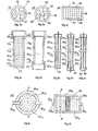
- various structures of membranes that are selectively permeable to hydrogen are represented, and in particular 10 ab structures, in the form of short rods (diameter 20 mm and length 120 mm), structures 24 abc shaped long sticks (diameter 8 mm and length 400 mm) and structures 40 ab, in the form of circular plates or elliptical 40a (diameter of 100 to 200 mm) or rectangular or square 40b (100 to 400 mm side), having a thickness of 3 to 8 mm.
- these various structures all comprise, from the outside, (1) an ultra-thin metal filter layer 12, 26 or 42, (2) an intermediate thin layer 14, 28 or 44 and (3) a rigid sintered substrate, 16, 30 or 46 (Fig. 1 abc).
- the ultra-thin filtration layer is made of palladium alloy (70 to 80%) and silver (20 to 30%) and its thickness is 3 to 4 microns.
- the intermediate thin layer is made from an ultra-fine powder, with a suitable particle size (range of 3 to 5 microns, for example), nickel or superalloy based on nickel. It is up to 50 microns thick and encloses relatively small open pores, below the micron, which gives it a particularly smooth surface but reduced porosity and permeability.
- the rigid and sintered body of the substrate is made from a relatively fine powder, with a suitable particle size (range of 30 to 50 microns for example), in Inconel 600. It encloses relatively large open pores ranging from a few microns to about ten microns, which give it porosity and relative permeability large but also, as mentioned above, a relatively large roughness. It should be noted that the composition given above for the filter layer 12-26-42 has been exemplified and that a palladium-based alloy including silver and / or nickel may also be used. suit.
- Inconel 600 is a stainless superalloy comprising 75% nickel, 15.5% chromium and 8% iron, to which are added low proportions of carbon, manganese and silica.
- the melting temperature of Inconel is 1.370 ° C, its modulus of elasticity of 200 GPa and its tensile yield strength of 800 MPa.
- the values of the three preceding characteristics of the Inconel 600 are substantially equal to or slightly greater than those of a material used by several of the authors of the above-mentioned patents, namely stainless steel. of the type 304.
- the preferred choice of Inconel for constituting the substrate 16-30-46 is determined by its coefficient of thermal expansion very close to that of the palladium while the thermal expansion coefficient of the steel in question is relatively distant. As noted above, such a coefficient makes this steel unfit for use in some processing chambers.
- Inconel and nickel-based alloys known for their low coefficient of thermal expansion are suitable for all types of fuel gas treatment chambers.
- a long stick-shaped structure 24 has an axial reinforcement 32, made of Inconel 600.
- a plate structure 40 has a metallic edge 48 also made of Inconel 600.
- the short rod structures 10 ab or long 24 abc all have at one end a collar 20 ab or 34 abc, preferably Inconel 600, welded to the intermediate thin layer 14 ab or 28 abc, by a weld bead compatible.
- These collars 20a or 34a of structures 10a-24a of glove membrane membranes (an ultra-thin filtration layer 13 or 27 is deposited on the end edge) are intended to ensure both the evacuation of hydrogen extracting and fixing these structures on a collector pipe.
- the short rod structures 10b or 24b long comprise a collar 22 or 36, fixed at the other end, in place of the ultra-thin layer 13 or 27.
- These collars 22-36 are provided for injecting a neutral carrier gas ( nitrogen, for example) in the substrate 16 or 30, to drive the hydrogen produced, as it is extracted.
- a neutral carrier gas nitrogen, for example
- the long stick structures 24 abc all comprise a rigid metal axial armature 32 abc, Inconel 600, which gives them the shape of rods.
- the frames 32 ab are solid rods 2 mm in diameter and the frame 32c, a hollow rod of 3 and 1.5 mm in outer and inner diameters.
- the two structures 24a and 24c of glove membranes differ from each other in that the hollow axial armature 32c opens into a cavity 38 formed in a cup 40, welded to the other end of the long rod 24c, instead of the ultra-thin layer 27 of the pencil 24a. This, in order to allow the use of a hydrogen carrier gas extracted by a glove membrane.
- the 32 abc armatures are also made of Inconel 600, a material with interesting mechanical characteristics, adapted to give the permeable porous bodies structures in long pencils 24 abc which incorporate them, a solidity and a stiffness sufficient to allow easy handling and good resistance to shocks inevitably suffered, during their use in fuel gas processors mounted on vehicles.
- the axial reinforcement 32 a-b-c of the rods 24 a-b-c protrude from the clamps 34 a-b and 34c-36 so as to be welded to the hydrogen collecting duct for the first two and to the vector gas injector duct for the last two. This provision is intended to improve the efficiency of fasteners structures.
- the plate structures, circular 40a and rectangular 40b respectively comprise metal borders 48 a-b, in which are embedded watertight substrates 46 a-b according to the invention.
- two plies formed of several relatively thin rigid metal rods may, before making the substrate 46 ab, be arranged in a cross in the borders 48 ab and welded to them, in order to play the same role as the axial reinforcement 32 abc long rods referred to above.
- relatively elongated rectangular or relatively elongated plates only one of these sheets, as in FIG. 4b, connecting the central portions of their nearest edge sections, may be sufficient.
- the borders 48 a-b each comprise two opposite orifices, connected to conduits 50a-52a and 50b-52b, respectively assigned to an injection of carrier gas and the evacuation of the extracted hydrogen. In the absence of carrier gas, the conduits 50 a-b can be removed.
- the substrates 16, 30 or 46 are made by appropriate sintering (see above), adapted to the desired porosity and permeability, in molds of suitable shapes, of relatively fine Inconel 600 grains, with a calibrated granulometry, which are suitable, following this operation, to generate rigid bodies, high porosity and permeability, enclosing open pores measuring up to ten microns.
- Such molds with appropriate shapes will be two half-cylinders for the rod substrates and two plates for the plates, one of these plates having a hollow having a shape identical to the outer shape of the edge 48 and a depth identical to its thickness.
- thin wires of thermo-destructible material are previously arranged in several layers in the mass of metal powder poured into the mold before sintering.
- a network of micro-channels or veinlets such as 17, 31 or 47, is constituted, which appears in points in Figures 1 a-b-c.
- the veinlets 17a-b and 47b shown in dashed lines in FIGS. 2a and 4b, are longitudinal (those of the rods of FIGS. 2b and 3a-b-c have been omitted) and the venules 47a of FIG. 4a follow curved lines connecting the orifices 50a-52a of the border 48a.
- the intermediate thin layer 14 is produced by depositing on the body 16, a suitable gel, containing an ultra-fine metal powder, calibrated granulometry, nickel or a nickel-based superalloy (which may be Inconel 600), formed of small grains, adapted to generate, following a proper sintering operation; open pores, communicating with each other, below the micron.
- the porosity and permeability of the intermediate thin layer 14 (which is 30 to 50 microns thick) are relatively small but its small roughness gives its outer surface a particularly smooth state which is quite suitable as a support for the deposition of an ultra-thin metal filter layer having a thickness of 2 to 4 microns.
- This ultra-thin filter layer 12 may, with reference to the published documents referred to above, be made by depositing the alloy of palladium and silver, carried out by means of any technique adapted for this purpose, known for its effectiveness, in particular one of those referred to above.
- the ultra-thin filter layer 12 is almost perfectly continuous, that is to say practically without micro-holes or micro-fissures, which makes it almost completely impermeable to all gas other than hydrogen, the impurity content of pure hydrogen thus filtered down to about 5 ppm, when the thickness of the filtration layer is 4 to 5 microns.
- the thermal expansion coefficients of these two components and of the filtration layer 12, made of palladium or palladium alloy and silver structures ab, 24 abc and 40 ab, are substantially identical. This minimizes the problems of differential expansion between the components of the filter structures according to the invention, in the reaction chambers of combustible gas processors, operating at temperatures ranging from 300 to 600 ° C. It should also be noted that this temperature range is the one in which the selective permeability with respect to hydrogen of an ultra-thin layer of palladium alloy and silver is maximal and that this selective permeability decreases rapidly. at temperatures below the low threshold of this range.
- the total pressure can reach 12 to 15 bars with a hydrogen partial pressure of about 3 to 6 bars.
- the hydrogen pressure is nearly 2 bar lower than the hydrogen partial pressure existing upstream.
- the ultra-thin membrane 12 can be subjected to a total differential pressure substantially greater than 10 bar.
- the ultrathin membrane membrane structures according to the invention can have both large areas and small individual footprints, while being adapted to withstand high temperatures and pressures.
- FIG. 5 shows the cross section of a cold plasma reaction chamber 54 of a fuel gas processor, a hydrogen generator, of the type described in the international patent application WO 98/28223 referred to above.
- this chamber 58 is installed an axial cylindrical electrode 60 200 mm long, provided with an insulating sheath 62, with a high dielectric coefficient, ceramic 3 mm thick, giving this electrode isolated an outer diameter of 20 mm. All around and at a short distance (3 mm for example) from this insulated electrode 60-62, are symmetrically arranged in a circle, six short cylindrical rod structures 64 1 ... 6 , according to one of the models described in FIGS. ab. These rods have the same dimensions as the electrode.
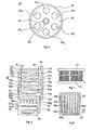
- FIGS. 6-8 represent the longitudinal views of two fuel gas processors, whose hydrogen productivity is significantly improved by the use of selectively hydrogen permeable membrane structures according to the invention, associated with isolated electrodes and baskets containing a suitable catalyst.
- the dimensions of the various elements that constitute the reaction chambers of these processors are obviously given below, solely by way of non-limiting examples.
- the reaction chamber 65 of a processor intended to be installed on an automobile, has a cylindrical envelope 66, 50 cm in diameter and length, in accordance with the specifications of the envelope 56 of FIG.
- these sets of structures 68 have the form of square grids of 300 mm side and 8 mm thick. They consist of long rod membranes, of the two-neck type described in FIG. 3b, the two ends of which are welded to two hollow beams 70 abcd and 72 abcd, assigned to the vector gas injection for the first and second the collection of hydrogen for the seconds.
- the hollow beams 70 and 72 protrude from the grid and are respectively connected to two pipes 74 and 76 which supply the carrier gas (nitrogen, for example) for the first and the evacuation of the hydrogen produced in the chamber for the second.
- the gap between the rods of the structures 68 is small ( ⁇ 1 mm), so that the hydrogen-filtering surface of each grid is a little less than three times the area of the square that it forms.
- These grids 68 a-b-c-d are rigidly fixed to a not shown frame, installed in the chamber 65, and they are separated from each other by 12 mm intervals.
- Electrodes 78 a-b Under the grids filtering the hydrogen 68 a-c, are installed and fixed to the same frame, electrodes 78 a-b, also in the form of grids externally identical to the grids 68 a-c.
- These electrode grids consist of long rods, similar to those of the grids 68 ac, which comprise an axial electrode and an insulating sheath respectively conforming to the constituents 60-62 of the insulated electrode shown in Figure 5.
- the rods of the grids 68 ab and 78 ab are staggered and the free spaces between them are at least 2 mm.
- FIG. 7 represents the external appearance of the grids of structures filtering hydrogen and the grids of electrodes referred to above.
- the square grids of the processor of FIG. 6 are 30 cm apart and each comprise thirty four rods 28 cm long and 8 mm in diameter spaced from each other by 0.8 mm. The ends of these rods are fixed to two overhanging beams 71 and 73 36 cm long and 1 cm in diameter. In the case of a grid of filtering structures, these beams 71-73 are ducts respectively assigned to the injection of carrier gas and the evacuation of the extracted hydrogen.
- the beams 71-73 are insulated electrical conductors ensuring the supply of these electrodes, one end of one of these conductors being adapted to establish a connection with a generator.
- Such an electrode grid may first of all constitute a naked assembly, to which a ceramic overmoulding is then applied during a sintering operation.
- these beams 71-73 also ensure the attachment to the frame referred to above of the two types of grids concerned.
- baskets 80 ab Under the grids 68 bd are installed and fixed to the frame referred to above, two square wire baskets 80 ab with a rigid edge, having 300 mm side as the filter grids 68 abcd but a thickness of 10 mm, so that the gaps between these baskets and these grids are about 1 mm.
- These baskets 80 ab contain a catalyst of known type, formed of ceramic granules coated with a mixture of iron and chromium oxides, specific for the so-called "water-gas shift" reaction, in the temperature range 300 to 550 ° C (which corresponds to the maximum efficiency range of the filtering structures according to the invention). This reaction will be presented below.
- baskets they are, given their constitution, perfectly permeable to gases.
- the electrodes 78 ab are connected, by high electrical insulated conductors 82, to a generator 84 delivering a very high alternating voltage (10 to 20 kV) at high frequency (1 MHz, for example), pulsed with a period of 1 ms, for example.
- Ducts 86 1 ... 6 installed at the outlet of a gas conditioning cell 88, supply the gas to be treated to the reaction chamber 65 and, for this purpose, open onto regularly distributed holes at the bottom. of the envelope 66 of this chamber. Thanks to the grid shape of the two electrodes 78 ab and the four filter structures 68 abcd as well as the high permeability of the pellet baskets 82 ab, the different gas mixtures, which circulate in the reaction chamber 65, do so in the best conditions.
- the gases supplied by the ducts 86 constitute an appropriate primary mixture of combustible gas (hydrocarbon or alcohol in particular), water vapor and air.
- This appropriate mixture is carried out in the conditioning cell 88 which receives each of the three gases concerned, to be stirred, heated and compressed, and finally, delivered with relative flow rates and partial pressures, at a total pressure of 10 to 15 hours. bars and a temperature of 300 to 550 ° C, as required by the reaction chamber 65 to operate in conditions providing the best results sought.
- a pipe 90 ensures the evacuation of the carbon dioxide produced in the chamber 65.
- the reaction chamber 92 of a processor 91 using other filtering structures according to the invention, is represented.
- the description of this chamber 92 will only relate to what distinguishes it from the chamber 66 of the processor 65 of FIG. 6.
- this chamber 92 are arranged with intervals of 12 mm, two groups each comprising twenty filtering structures according to the invention (of which only four structures, 94 abcd, are represented) in the form of rectangular plates of large dimensions (for example 30 x 20 cm) and 8 mm thick, in accordance with that described in Figure 4b.
- two filter plates 94 are alternately arranged two insulated electrodes, such as 96 ab, shaped rectangular plates measuring 15 x 20 cm and 8 mm thick and two rectangular baskets perforated rigid border, such 98 ab, also measuring 15 x 20 cm but 11 mm thick, filled with catalyst granules identical to precedents.
- the flow direction of the carrier gas in the filter structures 94 abcd and that of the reactive mixture injected into the chamber, will be reversed from one another. All of these forty groups of plates have a square cross section of 40 cm side and a length of 60 cm. A cylindrical envelope 93 60 cm in diameter and 80 cm long will suit them. The total area of these membrane structures thus collected is 960 dm 2 .
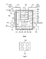
- FIG. 9a shows the longitudinal sectional diagram of a hydrogen purification apparatus and Figure 9b is a cross-sectional view of its heating chamber.
- the hydrogen to be purified is in particular usual industrial hydrogen (containing about 10 -4 impurities), with the objective of reducing this proportion of impurities by up to 5 ppm.
- This apparatus 100 mainly comprises a filtration chamber 102 and a heating chamber 104.
- the filtration chamber 102 comprises a cylindrical casing 106, made of stainless steel, enclosing a relatively large number of membranes 108 1 ... n selectively permeable to the hydrogen, in the form of square grids 30 cm in length, according to FIG. 7.
- the number of membrane-grids is, with the pressure, one of the parameters determined by the flow rate of pure hydrogen to obtain.
- Each of the grid membranes 108 is connected to two ducts 110 and 112, respectively assigned to the carrier gas supply and to the collection of the extracted pure hydrogen, which pass through the downstream bottom 114 of the filtration chamber 102.
- the heating chamber 104 comprises a boiler 116 and a burner 118, disposed upstream of several ducts 120, of high thermal conduction, which pass through the boiler 116 (see FIG. 9b) and open into a cavity 122 communicating with a chimney 124 by a perforated partition 126.
- the chimney 124 constitutes a duct, with a cross-section in a ring, which surrounds the wall of the filtration chamber 102.
- the boiler 116 is separated from the filtration chamber 102 by a dividing wall 128, provided with perforations, adapted to uniformly distribute the stream of hydrogen to be purified entering the chamber 102.
- the boiler 116 is supplied with hydrogen to be purified by a compressor 130 which generates an overpressure of 4 to 10 bar and opens into a distribution box 132, communicating with the boiler 116 by a perforated partition 134.
- a conduit 136 of the hy Residual drogen is connected, which leads to the inlet of the hearth 118, which is also supplied with compressed air by a compressor 138.
- thermocouple 140 connected (by means not shown) to a regulating device 142, adapted to produce a flow control signal of the air compressor 138.
- Achieving optimally conversions above means including ensuring that the amount of heat consumed by the reaction (2) highly endothermic is substantially equal to or slightly less than the amount of heat released by the partial oxidation reaction (1) strongly exothermic. A good combination of theory and experimentation achieves this goal. The same is true for the two moderately exothermic (4) and endothermic (3) reactions.
- a set of reactions defined by equations (1) - (2) - (3) above then occurs, the persistence duration of which is significantly greater than the duration of the barrier electrical discharge that started it.
- a secondary mixture of hydrogen and residual gases mainly comprising carbon monoxide (a poison for PEM fuel cells) and carbon dioxide, is produced on this occasion.
- the structures 64 of hydrogen-permeable membranes of the reaction chamber 58 extract the hydrogen produced as it is produced. This allows the three reactions (1), (2) and (3) to be performed at best, in a particularly small footprint. But this chamber 58, whose architecture exactly reproduces the teaching of the patent application cited by reference, also produces the residual gas mixture referred to above, which mixes, despite the ability to produce hydrogen that it has again, is, according to this teaching, only recycled in heat, in the boiler of the conditioning cell associated with the reaction chamber.
- the reaction chambers 65 and 92 with a relatively small space requirement, of processors, improved by the use of high pressure and high temperature membranes according to the invention, alternatively associated with insulated electrodes and with adequate catalyst baskets, produce, in separate discharge pipes, such as 76 and 90, with high efficiency and therefore a high yield, essentially almost pure hydrogen and carbon dioxide (a residue of the three components of the initial primary mixture is however generally added to the latter).
- the hydrogen produced in the reaction chambers 58-65-92 is generally intended to be used for the supply of PEM fuel cells referred to above.
- PEM fuel cells referred to above.
- the reaction chamber 58 which is at most 12 cm in ID and 30 cm long, can provide a sufficient amount of hydrogen. to power a PEM battery producing 750 W. This opens interesting applications in many areas, especially in the leisure industry.
- reaction chamber 92 of Fig 8 which, with a small footprint, include plate filter structures, capable of feeding a PEM battery delivering 96 kW.
- the hydrogen to be purified which enters the compressor 130 between cold and at low pressure, is injected into the distribution box 132 and into the boiler 116.
- the purification apparatus 100 this boiler 116. is itself cold, so that all of the hydrogen thus injected by the compressor 130, passes through the filtration chamber 102 and the recovery conduit 136 to result in the burner inlet 118.
- the selectively hydrogen-permeable membrane membranes 108 1 ... n which occupy the major part of the filtration chamber 102, are cold and therefore can not operate. their operating temperatures being between 300 and 550 ° C.
- the injected hydrogen is mixed with the compressed air supplied by the compressor.
- the filtration chamber 102 is also heated by the ring chimney 124, insulated by the insulating sheath 144, which surrounds it.
- thermocouple 140 which sends a signal to the air compressor 138 rate control device 142, makes it possible to regulate the temperature of the filtration chamber 102 to an optimum value.
- the pure hydrogen is extracted by membranes 108, operating under the best conditions, then it is discharged through the collector duct 112, driven by the carrier gas introduced into the duct 110.
- the residual hydrogen which results, has a coefficient of impurities much higher than that of the hydrogen to be purified initially injected but a pressure at least one or two bars lower than that of the latter.
- This residual hydrogen is discharged through the recovery duct 136 and injected into the burner 118 where it is used as indicated above.
- a conventional industrial hydrogen purification apparatus is produced, which allows to have pure hydrogen (impurity rate generally less than 10 ppm), which allows its use to feed batteries in the best conditions.
- PEM fuel type PEM fuel type.
- the hydrogen purification apparatus described in Figures 9 a-b can be greatly simplified.
- the filtration chamber will contain a single membrane, of the short rod type described in FIG. 2b, and the heating chamber will contain an electric heating resistor, supplied with a controlled current as a function of the temperature of the heater. filtration chamber, measured by a thermocouple. The lagging sheath will be preserved but the chimney will of course be removed as well as the effluent recovery duct of the filtration chamber.
- the hydrogen with a relatively high level of impurities which will then be in the filtration chamber, will be evacuated by action on a suitable tap.
- the stream of hydrogen thus purified could be introduced into a complementary treatment chamber, operating at temperatures of 200 to 250 ° C., carrying out the elimination of CO, by appropriate catalysis well known to the industry concerned.
- a complementary treatment chamber operating at temperatures of 200 to 250 ° C., carrying out the elimination of CO, by appropriate catalysis well known to the industry concerned.
- Such an operation can make use of several types of catalysts and in particular ruthenium deposited on granules of alumina.
- short or long rod structures in glove fingers or not, may, in the same reaction chamber, be associated with insulated electrodes and catalyst baskets, in the form of plates.
- insulated electrodes and catalyst baskets in the form of plates.
- Inconel 600 presented above in preference may be replaced by other grades of Inconel or even by certain types of Hastelloy.
- the latter are also nickel-based superalloys incorporating chromium and iron, whose mechanical characteristics and high temperature chemical stability are close to those of stainless steel and the coefficient of thermal expansion of at least one of them, lower than that of palladium, namely 11.3 10 -6 / ° C.
- catalyst baskets as long and wide as the filter structures 94 abcd (or granules of bulk catalysts) will be interposed between these structures, the flow direction of the gas vector in these structures being the inverse of the direction of the flow of reactive gases circulating in the chamber.
- the beneficial effect of the membrane structures filtering the hydrogen according to the invention is recalled: elimination of the reverse reactions and displacement of the chemical equilibrium in the direction of a more complete reaction of conversion of CO to CO 2 and thus a significant increase in the efficiency of the processes implemented in these processors.
- This effect increases with the pressure and when the temperature of the reaction mixture is in the range of the optimum operating temperatures of the filtration layers of the structures according to the invention.
Claims (16)
- Weitergebildete Verbundstruktur einer selektiv wasserstoffdurchlässigen Membran, (10-24-40), bestehend aus einer kontinuierlichen Filtrationsschicht (12-26-42), die eine Dicke von einigen Mikronen aufweist und aus Palladium oder einer Legierung auf Basis von Palladium erstellt ist, die auf einem porösen starren feuerbeständigen Substrat abgesetzt (16-30-46) ist, der mit einer Sammelleitung (20-34-52) des extrahierten Wasserstoffs verbunden ist, gekennzeichnet dadurch, dass:- besagter Substrat ein gesinterter durchlässiger Metallkörper (16-30-46) mit einem guten mechanischen Widerstand und offenen Poren ist, die einige Mikronen bis zu etwa zehn Mikronen messen;- eine dünne Metallschicht (14-28-44), die sogenannte Zwischenschicht, die eine Dicke von etwa zwanzig bis fünfzig Mikronen aufweist und offene Poren von unter einem Mikron einschliesst, wird auf dem Substratkörper aufgetragen;- der Substratkörper und die Zwischenschicht werden aus einem Metall oder einer Legierung erstellt, die im Bereich der benutzten Temperaturen und Drücke der Struktur Wärmeausdehnungs- und Expansions-Koeffizienten in Gegenwart von Wasserstoff aufweisen, wobei beide mit jenen des Palladiums kompatibel sind;- das Material, das die Zwischenschicht bildet, weist in besagtem Bereich eine befriedigende chemische Stabilität bezüglich der Filtrationsschicht und des Substratkörpers auf.
- Struktur einer selektiv wasserstoffdurchlässigen Membran nach Anspruch 1, gekennzeichnet dadurch, dass der WärmeausdehnungsKoeffizient der den Substratkörper und die Zwischenschicht bildenden Materialien niedriger, höchstens so hoch, ein wenig höher als jener des die Filtrationsschicht bildenden Materials ist.
- Struktur der selektiv wasserstoffdurchlässigen Membran nach Anspruch 2, gekennzeichnet dadurch, dass:- die ultradünne Filtrationsschicht (12-26-42) aus einer Legierung auf Basis von Palladium, einschliesslich Silber und/oder Nickel erstellt ist;- der gesinterte Körper (16-30-46) des genannten Substrats wird aus einem verhältnismäßig feinen Puder mit einer geeigneten Korngrösse vorbereitet, das aus einer Superlegierung auf Basis von Nickel, einschließlich Chrom und Eisen und insbesondere aus einem Puder von Inconel 600 gebildet ist;- die Zwischenschicht (14-28-44) wird aus einem ultrafeinen Puder mit geeigneter Korngrösse, aus Nickel oder einer dem benutzten Substratkörper ähnlichen Superlegierung vorbereitet;- die Filtrationsschicht wird durch Mikroschweissungen an die oberflächlichen Kornspitzen der Zwischenschicht fixiert.
- Struktur einer selektiv wasserstoffdurchlässigen Membran nach einem der vorangehenden Ansprüche, gekennzeichnet dadurch, dass der Körper (16-34-46) des besagten Substrats Äderchen (17-31-47) aufweist, die so angepasst sind, um die Durchlässigkeit zu verbessern.
- Struktur einer selektiv wasserstoffdurchlässigen Membran nach einem der vorangehenden Ansprüche, gekennzeichnet dadurch, dass besagter Substrat (16-30) ein zylindrisches Stäbchen (10-24) ist, das an einem Ende mit einer Manschette (20-34) zum Ablassen des extrahierten Wasserstoffs versehen ist und gegebenenfalls mit einer Manschette (22-36) zur Vektorgasversorgung am anderen Ende ausgestattet ist.
- Membranstruktur nach Anspruch 5, gekennzeichnet dadurch, dass besagtes zylindrisches Stäbchen (24 a-b-c) verhältnismäßig lang ist und eine axiale starre Metallarmierung (32 a-b-c) umfasst, die an dasselbe angepasst ist, um ihm einen guten mechanischen Widerstand zu verleihen.
- Struktur einer selektiv wasserstoffdurchlässigen Membran, gekennzeichnet dadurch, dass diese in Form eines Gitters vorliegt, das vorzugsweise viereckig und verhältnismäßig groß ist, bestehend aus einer verhältnismäßig bedeutenden Anzahl von Stäbchen nach Anspruch 6, die auf einer geringen Entfernung voneinander angeordnet und fest auf zwei hohlen Querträgern (71-73) montiert sind, die jeweils zur Sammlung des extrahierten Wasserstoffs und zur Vektorgas-Versorgung bestimmt sind.
- Membranstruktur nach Anspruch 7, gekennzeichnet dadurch, dass besagtes verhältnismäßig langes Stäbchen (24c) in der Art eines Handschuhfingers mit Vektorgasinjektion vorliegen soll, seine axiale Armierung (32c) ist hohl und für besagte Injektion bestimmt und sie mündet in einem Hohlraum (38) der in einer Schale (40) eingerichtet ist, die am besagten anderen Ende verschweißt ist.
- Selektiv wasserdurchlässige Membranstruktur gemäss einem der Ansprüche 1 bis 4, gekennzeichnet dadurch, dass besagter Substrat, der einen porösen Körper (46) und eine Zwischenschicht (44) umfasst, eine Platte ist, die dicht in einem Metallrand (48 a-b) eingefasst ist, der mit einer Öffnung versehen ist, die mit einer Leitung (52 a-b) zum Ablassen des extrahierten Wasserstoffs und gegebenenfalls mit einer anderen der ersten Öffnung gegenüberliegenden Öffnung verbunden ist, die mit einer Vektorgas-Versorgungsleitung (50 a-b) verbunden ist.
- Membranstruktur nach Anspruch 9, gekennzeichnet dadurch, dass besagte Platte verhältnismäßig bedeutende Dimensionen besitzt, besagter Substrat mit einer starren inneren Metallarmierung (49) versehen ist, die so daran angepasst ist, um ihm einen guten mechanischen Widerstand zu verleihen.
- Brenngasprozessor (54-65-91), in welchem eine Reaktionskammer (58-66-92) mit kaltem Plasma, die unter den passenden Verhältnissen durch eine Konditionierungszelle (88) versorgt wird, indem sie eine Primärmischung des genannten Gases aus Wasserdampf und Luft aufbringt, eine sekundäre Mischung aus Wasserstoff, Kohlenmonoxid und -dioxid erzeugt, gekennzeichnet dadurch dass:- besagte Kammer (58-66-92) umfasst mehrere Strukturen von selektiv wasserstoffdurchlässigen Membranen (64-68-94) nach einem der obengenannten Ansprüche 1 bis 10, die mit einem gemeinsamen Wasserstoffkollektor (76) verbunden sind, wobei besagte Strukturen die gegebene Form und Dimensionen aufweisen;- in unmittelbarer Nähe dieser Strukturen sind eine oder mehrere Elektroden angeordnet, die mit einem feuerbeständigen Isoliermantel (60-62, 68 a-b, 96 a-b) mit einem starken dielektrischen Koeffizienten versehen sind, die eine Form und Dimensionen aufweisen, die so angepasst sind, um ihnen zu gestatten, wirksam mit besagten Strukturen zusammenzuwirken, um eine Einheit zu bilden, die dazu bestimmt ist, als Erwiderung auf eine angemessene elektrische Stromversorgung (84) Barrieren von elektrischen Entladungen zu bilden, indem besagtes kaltes Plasma in den Räumen erzeugt wird, die die Elektroden und Strukturen trennen.
- Brenngasprozessor nach Anspruch 11, gekennzeichnet dadurch, dass in der Reaktionskammer (65-92) jede Einheit, die aus einer isolierten Elektrode (78 a-c oder 96 a-b) gebildet ist, die einer Filtrierstruktur (68 ab oder 94) zugeordnet ist, gefolgt von einer aus einer isolierten Elektrode (78 b-d) und aus einem Korb (80 a-b oder 98 a-b) gebildeten Einheit, die katalytische Granulate der sogenannten «Wasser-Gas Shift»- Reaktion mit erhöhter Temperatur enthält.
- Gasprozessor, der eine Reaktionskammer umfasst, die mit einem spezifischen chemischen Katalysator der betroffenen Reaktion versehen ist, gekennzeichnet dadurch, dass die Strukturen von selektiv wasserstoffdurchlässigen Membranen nach einem der Ansprüche 1 bis 10 in unmittelbarer Nähe des genannten Katalysators angeordnet sind.
- Brennstoffgasprozessor nach den Patentansprüchen 11 oder 12, gekennzeichnet dadurch, dass:- die filtrierenden Strukturen (68 a-b-c-d) und die isolierten Elektroden (78 a-b-c-d) die Form von langen Stiften (24 a-b) aufweisen, die in Gittern derselben Dimensionen, insbesondere viereckig, zusammengebaut sind;- besagte Gitter sind aus einer verhältnismäßig bedeutenden Zahl von fast aneinander gesetzten Stiften gebildet, die an zwei auslaufenden Trägern (71-73) befestigt sind, die entweder Neutralgasinjektionsleitungen und Wasserstoffablassleitungen für die filtrierenden Strukturen (68) oder isolierte elektrische Verbindungsleiter (79 a-b) für die isolierten Elektroden (78) sind, wobei besagte Träger (71-73) so angepasst sind, um fest auf einen in der Reaktionskammer installierten Ständer aufgebaut zu werden.
- Wasserstoffreinigungsgerät (100), gekennzeichnet dadurch, dass es folgendes umfasst:- eine aus einer feuerbeständigen Umhüllung (106) bestehende Filtrationskammer (102), die durch eine isolierte Abdeckung (144) wärmeisoliert ist, die eine oder mehrere selektiv wasserstoffdurchlässige Membrane (1081...n) einschliesst, in der durch einen der Patentansprüche 1 bis 10 oben definierten Art, wobei besagte Membrane an zwei gemeinsame Leitungen (110-112) angeschlossen sind, die jeweils für die Vektorgas-Versorgung und die Sammlung des extrahierten Wasserstoffs bestimmt sind;- Heizmittel (118-120-126), Temperaturregelungsmittel (140-142-138) und Kompressionsmittel (130), die so angepasst sind, um dem zu reinigenden Wasserstoffstrom eine Temperatur und einen Druck zu geben, die in den Temperatur- und Druckbereichen liegen, die dem optimalen Betrieb der Membrane (108) entsprechen.
- Wasserstoffreinigungsgerät nach Anspruch 15, gekennzeichnet dadurch, dass:- besagte Heizmittel einen Kessel (116) und einen Brenner (118) umfassen, die den Heizleitungen (120) mit hoher thermischen Leitung, die durch den Kessel (116) hindurch führen, zugeordnet sind;- der Kessel (116) wird vom zu reinigenden Wasserstoff im Überdruck versorgt und er ist mit der Filtrationsskammer (102) über eine gelochte Scheidewand (122) verbunden;- der Brenner (118) wird vom restlichen Wasserstoff gespeist, der abwärts aus der Filtrationskammer (102) durch eine Rücklaufleitung (136) und durch die Druckluft ausgeleert wird, die von einen Kompressor (138) zugeführt wird, dessen Durchflussleistung von einer Regelungsvorrichtung (142) abhängt und die über ein Signal kontrolliert wird, das von einem Thermoelement (140) ausgegeben wird, das in der Filtrationskammer (102) plaziert ist;- der Kamin (126) des Brenners (118) besitzt einen Ringabschnitt, dieser umgibt die Filtrationskammer (102) und sie ist durch die isolierte Decke (144) wärmebeständig.
Applications Claiming Priority (3)
| Application Number | Priority Date | Filing Date | Title |
|---|---|---|---|
| FR0102219A FR2820988B1 (fr) | 2001-02-19 | 2001-02-19 | Structures composites de membranes selectivement permeables a l'hydrogene et processeurs de gaz combustibles en faisant usage |
| FR0102219 | 2001-02-19 | ||
| PCT/FR2002/000578 WO2002066144A2 (fr) | 2001-02-19 | 2002-02-14 | Structures composites de membranes selectivement permeables a l'hydrogene et processeurs de gaz combustibles en faisant usage |
Publications (2)
| Publication Number | Publication Date |
|---|---|
| EP1361916A2 EP1361916A2 (de) | 2003-11-19 |
| EP1361916B1 true EP1361916B1 (de) | 2008-01-16 |
Family
ID=8860180
Family Applications (1)
| Application Number | Title | Priority Date | Filing Date |
|---|---|---|---|
| EP02704838A Expired - Lifetime EP1361916B1 (de) | 2001-02-19 | 2002-02-14 | Selektive, wasserstoffdurchlässige membranverbundstrukturen und brenngasprozessor unter verwendung derselben |
Country Status (8)
| Country | Link |
|---|---|
| US (1) | US7449052B2 (de) |
| EP (1) | EP1361916B1 (de) |
| JP (1) | JP2004526559A (de) |
| AT (1) | ATE383904T1 (de) |
| CA (1) | CA2438533C (de) |
| DE (1) | DE60224647D1 (de) |
| FR (1) | FR2820988B1 (de) |
| WO (1) | WO2002066144A2 (de) |
Families Citing this family (18)
| Publication number | Priority date | Publication date | Assignee | Title |
|---|---|---|---|---|
| CA2519769A1 (en) * | 2003-03-21 | 2004-10-07 | Worcester Polytechnic Institute | Composite gas separation modules having intermediate porous metal layers |
| DE602004016470D1 (de) * | 2003-03-21 | 2008-10-23 | Worcester Polytech Inst | Verfahren zum beheben von defekten bei der herstellung eines verbundmembran-gastrennungsmoduls |
| EP1608459A1 (de) * | 2003-03-21 | 2005-12-28 | Worcester Polytechnic Institute | Verfahren zur herstellung von verbundgastrennungsmodulen |
| EP1622698B1 (de) * | 2003-05-02 | 2010-01-06 | Worcester Polytechnic Institute | Verbundgastrennmodule mit zwischenschichten auf höher tammanntemperatur |
| US7125440B2 (en) * | 2003-06-04 | 2006-10-24 | Bossard Peter R | Composite structure for high efficiency hydrogen separation and its associated methods of manufacture and use |
| US7727596B2 (en) * | 2004-07-21 | 2010-06-01 | Worcester Polytechnic Institute | Method for fabricating a composite gas separation module |
| JP2008513337A (ja) * | 2004-09-21 | 2008-05-01 | ウスター ポリテクニック インスティチュート | 膜増強反応器 |
| WO2006034103A1 (en) * | 2004-09-21 | 2006-03-30 | Worcester Polytechic Institute | Reactor and process for steam reforming |
| CA2580585A1 (en) * | 2004-09-21 | 2006-03-30 | Worcester Polytechnic Institute | Membrane steam reformer |
| US7559979B2 (en) * | 2005-02-04 | 2009-07-14 | Ngk Insulators, Ltd. | Hydrogen separator and method for production thereof |
| US20070044663A1 (en) * | 2005-08-25 | 2007-03-01 | The University Of Chicago | Method for fabricating a hydrogen separation membrane on a porous substrate |
| JP4908821B2 (ja) * | 2005-10-28 | 2012-04-04 | トヨタ自動車株式会社 | 支持体付水素分離膜、それを備える燃料電池および水素分離装置ならびにそれらの製造方法 |
| JP4970556B2 (ja) * | 2007-02-20 | 2012-07-11 | シエル・インターナシヨナル・リサーチ・マートスハツペイ・ベー・ヴエー | ガス分離膜システムおよびその調製または再生方法および使用 |
| JP2010523315A (ja) | 2007-04-05 | 2010-07-15 | ウスター ポリテクニック インスティチュート | 多孔質アノード酸化層を有する複合構造および製造方法 |
| US8479487B2 (en) * | 2009-08-10 | 2013-07-09 | General Electric Company | Hybrid multichannel porous structure for hydrogen separation |
| US8652239B2 (en) | 2010-05-03 | 2014-02-18 | Worcester Polytechnic Institute | High permeance sulfur tolerant Pd/Cu alloy membranes |
| TWI473912B (zh) * | 2013-03-28 | 2015-02-21 | 國立成功大學 | New energy vehicle plasma hydrogen production unit |
| CN117250130B (zh) * | 2023-11-20 | 2024-02-06 | 华电重工机械有限公司 | 一种质子交换膜氢渗测试的方法 |
Family Cites Families (11)
| Publication number | Priority date | Publication date | Assignee | Title |
|---|---|---|---|---|
| US5645626A (en) * | 1990-08-10 | 1997-07-08 | Bend Research, Inc. | Composite hydrogen separation element and module |
| US5498278A (en) * | 1990-08-10 | 1996-03-12 | Bend Research, Inc. | Composite hydrogen separation element and module |
| US5217506A (en) * | 1990-08-10 | 1993-06-08 | Bend Research, Inc. | Hydrogen-permeable composite metal membrane and uses thereof |
| US5393325A (en) * | 1990-08-10 | 1995-02-28 | Bend Research, Inc. | Composite hydrogen separation metal membrane |
| US6461408B2 (en) * | 1995-11-06 | 2002-10-08 | Robert E. Buxbaum | Hydrogen generator |
| WO1997017125A1 (en) * | 1995-11-06 | 1997-05-15 | Buxbaum Robert E | Apparatus and methods for gas extraction |
| FR2757499B1 (fr) * | 1996-12-24 | 2001-09-14 | Etievant Claude | Generateur d'hydrogene |
| US6152987A (en) * | 1997-12-15 | 2000-11-28 | Worcester Polytechnic Institute | Hydrogen gas-extraction module and method of fabrication |
| US6207132B1 (en) * | 1998-12-04 | 2001-03-27 | Chinese Petroleum Corporation | Process for producing high purity hydrogen |
| US6653005B1 (en) * | 2000-05-10 | 2003-11-25 | University Of Central Florida | Portable hydrogen generator-fuel cell apparatus |
| US6923944B2 (en) * | 2000-07-07 | 2005-08-02 | Robert E. Buxbaum | Membrane reactor for gas extraction |
-
2001
- 2001-02-19 FR FR0102219A patent/FR2820988B1/fr not_active Expired - Lifetime
-
2002
- 2002-02-14 WO PCT/FR2002/000578 patent/WO2002066144A2/fr active IP Right Grant
- 2002-02-14 US US10/468,552 patent/US7449052B2/en not_active Expired - Fee Related
- 2002-02-14 CA CA2438533A patent/CA2438533C/fr not_active Expired - Lifetime
- 2002-02-14 DE DE60224647T patent/DE60224647D1/de not_active Expired - Lifetime
- 2002-02-14 AT AT02704838T patent/ATE383904T1/de not_active IP Right Cessation
- 2002-02-14 JP JP2002565698A patent/JP2004526559A/ja active Pending
- 2002-02-14 EP EP02704838A patent/EP1361916B1/de not_active Expired - Lifetime
Also Published As
| Publication number | Publication date |
|---|---|
| CA2438533C (fr) | 2010-05-11 |
| FR2820988B1 (fr) | 2003-04-25 |
| US7449052B2 (en) | 2008-11-11 |
| ATE383904T1 (de) | 2008-02-15 |
| EP1361916A2 (de) | 2003-11-19 |
| WO2002066144A3 (fr) | 2002-11-28 |
| US20050072304A1 (en) | 2005-04-07 |
| WO2002066144A2 (fr) | 2002-08-29 |
| JP2004526559A (ja) | 2004-09-02 |
| DE60224647D1 (de) | 2008-03-06 |
| FR2820988A1 (fr) | 2002-08-23 |
| CA2438533A1 (fr) | 2002-08-29 |
Similar Documents
| Publication | Publication Date | Title |
|---|---|---|
| EP1361916B1 (de) | Selektive, wasserstoffdurchlässige membranverbundstrukturen und brenngasprozessor unter verwendung derselben | |
| EP0952957B1 (de) | Verfahren und vorrichtungen zur herstellung von wasserstoff durch plasmareforming | |
| EP2984209B1 (de) | Verfahren zur herstellung von brenngas aus wasserelektrolyse oder co-elektrolyse mit h2o/co2 in derselben kammer, zugehöriger katalytischer reaktor und system | |
| EP0542597B1 (de) | Verfahren zur thermischen Pyrolyse von Kohlenwasserstoffen mit Elektroofen | |
| EP0272986B1 (de) | Verfahren und Vorrichtung zum Herstellung von Synthesegas mittels einer Flamme | |
| WO2004041425A1 (fr) | Reacteur a chauffage electrique pour le reformage en phase gazeuse | |
| FR2962050A1 (fr) | Procede de fonctionnement d'une membrane ceramique conductrice ionique mixte | |
| CA2580585A1 (en) | Membrane steam reformer | |
| FR2895392A1 (fr) | Procede et equipement pour produire de l'hydrogene a partir de l'energie solaire. | |
| FR2754740A1 (fr) | Composite actif a structure feuilletee comprenant un agent actif sous forme de granules | |
| EP1784354B1 (de) | Stufensystem zur herstellung gereinigten wasserstoffs aus einer reaktionsgasmischung mit einer kohlenwasserstoffverbindung | |
| US20140298993A1 (en) | Hydrogen separation membrane module which have mixing part | |
| FR2828012A1 (fr) | Installation de piles a combustible comportant deux unites de transformation pour une decomposition catalytique | |
| EP2694884B1 (de) | Solarsystem zur reproduktion der wirkung einer verbrennungsflamme | |
| FR2904819A1 (fr) | Procede de stockage de l'hydrogene, dispositif pour sa mise en oeuvre et applications | |
| EP1701777B1 (de) | Verbund mit einer gastrennmembran auf einem träger | |
| FR2960450A1 (fr) | Procede de production anaerobie d'hydrogene | |
| CA2042881A1 (fr) | Procede de conversion thermique du methane et reacteur pour la mise en oeuvre du procede | |
| EP0607379B1 (de) | Katalytische reinigungsvorrichtung für umgebungsluft sowie entsprechender katalysator | |
| EP3531053B1 (de) | Reaktor-wärmetauscher, der einspritz- und verteilungskanäle der reagenzien umfasst | |
| EP1358125A2 (de) | Verfahren und vorrichtung zur herstellung von wasserstoff durch teiloxidation von kohlenwasserstoffbrennstoffen | |
| WO1994002207A9 (fr) | Appareil catalytique pour purifier l'air ambiant et catalyseurs correspondants | |
| BE712074A (de) |
Legal Events
| Date | Code | Title | Description |
|---|---|---|---|
| PUAI | Public reference made under article 153(3) epc to a published international application that has entered the european phase |
Free format text: ORIGINAL CODE: 0009012 |
|
| 17P | Request for examination filed |
Effective date: 20030813 |
|
| AK | Designated contracting states |
Kind code of ref document: A2 Designated state(s): AT BE CH CY DE DK ES FI FR GB GR IE IT LI LU MC NL PT SE TR |
|
| AX | Request for extension of the european patent |
Extension state: AL LT LV MK RO SI |
|
| RAP1 | Party data changed (applicant data changed or rights of an application transferred) |
Owner name: COMPAGNIE EUROPEENNE DES TECHNOLOGIES DE L'HYDROGE |
|
| GRAP | Despatch of communication of intention to grant a patent |
Free format text: ORIGINAL CODE: EPIDOSNIGR1 |
|
| GRAS | Grant fee paid |
Free format text: ORIGINAL CODE: EPIDOSNIGR3 |
|
| GRAA | (expected) grant |
Free format text: ORIGINAL CODE: 0009210 |
|
| AK | Designated contracting states |
Kind code of ref document: B1 Designated state(s): AT BE CH CY DE DK ES FI FR GB GR IE IT LI LU MC NL PT SE TR |
|
| REG | Reference to a national code |
Ref country code: GB Ref legal event code: FG4D Free format text: NOT ENGLISH |
|
| REG | Reference to a national code |
Ref country code: CH Ref legal event code: EP |
|
| REG | Reference to a national code |
Ref country code: IE Ref legal event code: FG4D Free format text: LANGUAGE OF EP DOCUMENT: FRENCH |
|
| REF | Corresponds to: |
Ref document number: 60224647 Country of ref document: DE Date of ref document: 20080306 Kind code of ref document: P |
|
| PG25 | Lapsed in a contracting state [announced via postgrant information from national office to epo] |
Ref country code: NL Free format text: LAPSE BECAUSE OF FAILURE TO SUBMIT A TRANSLATION OF THE DESCRIPTION OR TO PAY THE FEE WITHIN THE PRESCRIBED TIME-LIMIT Effective date: 20080116 |
|
| REG | Reference to a national code |
Ref country code: CH Ref legal event code: NV Representative=s name: BUGNION S.A. |
|
| NLV1 | Nl: lapsed or annulled due to failure to fulfill the requirements of art. 29p and 29m of the patents act | ||
| PG25 | Lapsed in a contracting state [announced via postgrant information from national office to epo] |
Ref country code: ES Free format text: LAPSE BECAUSE OF FAILURE TO SUBMIT A TRANSLATION OF THE DESCRIPTION OR TO PAY THE FEE WITHIN THE PRESCRIBED TIME-LIMIT Effective date: 20080427 Ref country code: FI Free format text: LAPSE BECAUSE OF FAILURE TO SUBMIT A TRANSLATION OF THE DESCRIPTION OR TO PAY THE FEE WITHIN THE PRESCRIBED TIME-LIMIT Effective date: 20080116 |
|
| GBV | Gb: ep patent (uk) treated as always having been void in accordance with gb section 77(7)/1977 [no translation filed] | ||
| PG25 | Lapsed in a contracting state [announced via postgrant information from national office to epo] |
Ref country code: AT Free format text: LAPSE BECAUSE OF FAILURE TO SUBMIT A TRANSLATION OF THE DESCRIPTION OR TO PAY THE FEE WITHIN THE PRESCRIBED TIME-LIMIT Effective date: 20080116 |
|
| PG25 | Lapsed in a contracting state [announced via postgrant information from national office to epo] |
Ref country code: PT Free format text: LAPSE BECAUSE OF FAILURE TO SUBMIT A TRANSLATION OF THE DESCRIPTION OR TO PAY THE FEE WITHIN THE PRESCRIBED TIME-LIMIT Effective date: 20080616 |
|
| REG | Reference to a national code |
Ref country code: IE Ref legal event code: FD4D |
|
| PG25 | Lapsed in a contracting state [announced via postgrant information from national office to epo] |
Ref country code: IE Free format text: LAPSE BECAUSE OF FAILURE TO SUBMIT A TRANSLATION OF THE DESCRIPTION OR TO PAY THE FEE WITHIN THE PRESCRIBED TIME-LIMIT Effective date: 20080116 Ref country code: DK Free format text: LAPSE BECAUSE OF FAILURE TO SUBMIT A TRANSLATION OF THE DESCRIPTION OR TO PAY THE FEE WITHIN THE PRESCRIBED TIME-LIMIT Effective date: 20080116 Ref country code: DE Free format text: LAPSE BECAUSE OF FAILURE TO SUBMIT A TRANSLATION OF THE DESCRIPTION OR TO PAY THE FEE WITHIN THE PRESCRIBED TIME-LIMIT Effective date: 20080417 Ref country code: SE Free format text: LAPSE BECAUSE OF FAILURE TO SUBMIT A TRANSLATION OF THE DESCRIPTION OR TO PAY THE FEE WITHIN THE PRESCRIBED TIME-LIMIT Effective date: 20080416 |
|
| PLBE | No opposition filed within time limit |
Free format text: ORIGINAL CODE: 0009261 |
|
| STAA | Information on the status of an ep patent application or granted ep patent |
Free format text: STATUS: NO OPPOSITION FILED WITHIN TIME LIMIT |
|
| 26N | No opposition filed |
Effective date: 20081017 |
|
| PG25 | Lapsed in a contracting state [announced via postgrant information from national office to epo] |
Ref country code: GB Free format text: LAPSE BECAUSE OF FAILURE TO SUBMIT A TRANSLATION OF THE DESCRIPTION OR TO PAY THE FEE WITHIN THE PRESCRIBED TIME-LIMIT Effective date: 20080116 |
|
| PG25 | Lapsed in a contracting state [announced via postgrant information from national office to epo] |
Ref country code: CY Free format text: LAPSE BECAUSE OF FAILURE TO SUBMIT A TRANSLATION OF THE DESCRIPTION OR TO PAY THE FEE WITHIN THE PRESCRIBED TIME-LIMIT Effective date: 20080116 |
|
| PG25 | Lapsed in a contracting state [announced via postgrant information from national office to epo] |
Ref country code: IT Free format text: LAPSE BECAUSE OF FAILURE TO SUBMIT A TRANSLATION OF THE DESCRIPTION OR TO PAY THE FEE WITHIN THE PRESCRIBED TIME-LIMIT Effective date: 20080116 |
|
| REG | Reference to a national code |
Ref country code: CH Ref legal event code: NV Representative=s name: CABINET MOUTARD |
|
| PGFP | Annual fee paid to national office [announced via postgrant information from national office to epo] |
Ref country code: LU Payment date: 20100223 Year of fee payment: 9 Ref country code: MC Payment date: 20100215 Year of fee payment: 9 |
|
| PGFP | Annual fee paid to national office [announced via postgrant information from national office to epo] |
Ref country code: BE Payment date: 20100215 Year of fee payment: 9 |
|
| PG25 | Lapsed in a contracting state [announced via postgrant information from national office to epo] |
Ref country code: TR Free format text: LAPSE BECAUSE OF FAILURE TO SUBMIT A TRANSLATION OF THE DESCRIPTION OR TO PAY THE FEE WITHIN THE PRESCRIBED TIME-LIMIT Effective date: 20080116 |
|
| PG25 | Lapsed in a contracting state [announced via postgrant information from national office to epo] |
Ref country code: GR Free format text: LAPSE BECAUSE OF FAILURE TO SUBMIT A TRANSLATION OF THE DESCRIPTION OR TO PAY THE FEE WITHIN THE PRESCRIBED TIME-LIMIT Effective date: 20080417 |
|
| BERE | Be: lapsed |
Owner name: CIE EUROPEENNE DES TECHNOLOGIES DE L'HYDROGENE (C Effective date: 20110228 |
|
| PG25 | Lapsed in a contracting state [announced via postgrant information from national office to epo] |
Ref country code: MC Free format text: LAPSE BECAUSE OF NON-PAYMENT OF DUE FEES Effective date: 20110228 |
|
| PG25 | Lapsed in a contracting state [announced via postgrant information from national office to epo] |
Ref country code: BE Free format text: LAPSE BECAUSE OF NON-PAYMENT OF DUE FEES Effective date: 20110228 |
|
| PG25 | Lapsed in a contracting state [announced via postgrant information from national office to epo] |
Ref country code: LU Free format text: LAPSE BECAUSE OF NON-PAYMENT OF DUE FEES Effective date: 20110214 |
|
| REG | Reference to a national code |
Ref country code: FR Ref legal event code: PLFP Year of fee payment: 15 |
|
| REG | Reference to a national code |
Ref country code: FR Ref legal event code: PLFP Year of fee payment: 16 |
|
| REG | Reference to a national code |
Ref country code: FR Ref legal event code: PLFP Year of fee payment: 17 |
|
| PGFP | Annual fee paid to national office [announced via postgrant information from national office to epo] |
Ref country code: CH Payment date: 20210217 Year of fee payment: 20 Ref country code: FR Payment date: 20210226 Year of fee payment: 20 |
|
| REG | Reference to a national code |
Ref country code: CH Ref legal event code: PL |