EP2694884B1 - Solarsystem zur reproduktion der wirkung einer verbrennungsflamme - Google Patents
Solarsystem zur reproduktion der wirkung einer verbrennungsflamme Download PDFInfo
- Publication number
- EP2694884B1 EP2694884B1 EP12711670.5A EP12711670A EP2694884B1 EP 2694884 B1 EP2694884 B1 EP 2694884B1 EP 12711670 A EP12711670 A EP 12711670A EP 2694884 B1 EP2694884 B1 EP 2694884B1
- Authority
- EP
- European Patent Office
- Prior art keywords
- heat transfer
- solar
- transfer fluid
- temperature
- receiver
- Prior art date
- Legal status (The legal status is an assumption and is not a legal conclusion. Google has not performed a legal analysis and makes no representation as to the accuracy of the status listed.)
- Active
Links
Images


Classifications
-
- F—MECHANICAL ENGINEERING; LIGHTING; HEATING; WEAPONS; BLASTING
- F24—HEATING; RANGES; VENTILATING
- F24S—SOLAR HEAT COLLECTORS; SOLAR HEAT SYSTEMS
- F24S20/00—Solar heat collectors specially adapted for particular uses or environments
- F24S20/20—Solar heat collectors for receiving concentrated solar energy, e.g. receivers for solar power plants
-
- F—MECHANICAL ENGINEERING; LIGHTING; HEATING; WEAPONS; BLASTING
- F24—HEATING; RANGES; VENTILATING
- F24S—SOLAR HEAT COLLECTORS; SOLAR HEAT SYSTEMS
- F24S10/00—Solar heat collectors using working fluids
- F24S10/70—Solar heat collectors using working fluids the working fluids being conveyed through tubular absorbing conduits
-
- F—MECHANICAL ENGINEERING; LIGHTING; HEATING; WEAPONS; BLASTING
- F24—HEATING; RANGES; VENTILATING
- F24S—SOLAR HEAT COLLECTORS; SOLAR HEAT SYSTEMS
- F24S23/00—Arrangements for concentrating solar-rays for solar heat collectors
- F24S23/70—Arrangements for concentrating solar-rays for solar heat collectors with reflectors
-
- Y—GENERAL TAGGING OF NEW TECHNOLOGICAL DEVELOPMENTS; GENERAL TAGGING OF CROSS-SECTIONAL TECHNOLOGIES SPANNING OVER SEVERAL SECTIONS OF THE IPC; TECHNICAL SUBJECTS COVERED BY FORMER USPC CROSS-REFERENCE ART COLLECTIONS [XRACs] AND DIGESTS
- Y02—TECHNOLOGIES OR APPLICATIONS FOR MITIGATION OR ADAPTATION AGAINST CLIMATE CHANGE
- Y02E—REDUCTION OF GREENHOUSE GAS [GHG] EMISSIONS, RELATED TO ENERGY GENERATION, TRANSMISSION OR DISTRIBUTION
- Y02E10/00—Energy generation through renewable energy sources
- Y02E10/40—Solar thermal energy, e.g. solar towers
- Y02E10/44—Heat exchange systems
-
- Y—GENERAL TAGGING OF NEW TECHNOLOGICAL DEVELOPMENTS; GENERAL TAGGING OF CROSS-SECTIONAL TECHNOLOGIES SPANNING OVER SEVERAL SECTIONS OF THE IPC; TECHNICAL SUBJECTS COVERED BY FORMER USPC CROSS-REFERENCE ART COLLECTIONS [XRACs] AND DIGESTS
- Y02—TECHNOLOGIES OR APPLICATIONS FOR MITIGATION OR ADAPTATION AGAINST CLIMATE CHANGE
- Y02P—CLIMATE CHANGE MITIGATION TECHNOLOGIES IN THE PRODUCTION OR PROCESSING OF GOODS
- Y02P80/00—Climate change mitigation technologies for sector-wide applications
- Y02P80/20—Climate change mitigation technologies for sector-wide applications using renewable energy
Definitions
- the present invention relates to the field of solar thermal and thermochemical systems at high temperature.
- combustion flame is, with the plasma process, one of the only ways to obtain a heat input in a volume at the industrial level. Also referred to as “flame temperatures” are the temperatures to which these processes are subjected.
- combustion flame that can be obtained only from renewable energy, and in particular solar energy.
- the so-called concentrated solar systems allow the conversion of solar radiation into thermal energy, which is generally used for the production of electricity.
- a concentrating system is the tower plant.
- Such a system consists of a tower and a field of moving mirrors called heliostats which concentrates the radiation on a reduced area at the top of the tower.
- This area illuminated by the concentrated radiation receives several hundred times the direct solar radiation, and is equipped with a device called solar receiver whose function is to transmit this energy to a fluid (a liquid or a gas) circulating therein, typically turbined water vapor to produce electricity.
- a fluid typically turbined water vapor to produce electricity.
- FIG 1 a tower thermodynamic power plant comprising a tower 3, a heliostatic field 2, and the solar receiver 10.
- the solar receiver described in the patent application US 2010/0237291 consists of a cavity traversed by a plurality of tubes in which chemical compounds circulate which can react in so-called endothermic reactions, that is to say requiring high temperatures usually used under the effect of a combustion flame (cracking of methane for example).
- the outer wall of the tubes receives concentrated solar radiation, which carries it at high temperature: the tubes act as a transfer wall.
- the thermal input is not volume but surface: the heat is transferred to the chemical reagents by contact with the inner wall of the tubes. This surface thermal contribution poorly reproduces the effect of a combustion flame, since the chemical reaction takes place mainly at the level of the walls. This decreases the yield and leads to the appearance and growth of solid residue deposits on the walls (in this case pure carbon in the case of a cracking process), which quickly makes the unusable receiver: the deposits reduce the heat input and obstruct the tubes.
- the international patent application WO 03/049853 proposes a sealed solar receiver (a porthole makes it possible to let in the concentrated solar radiation), in which the chemical compounds to be heated circulate directly.
- a cloud of absorbent solid microparticles carbon black smoke, for example
- the thermal input is this time volumic (rigorously, the heat exchange takes place on the surface of the particles, but by the relatively uniform diffusion of the particles in the volume, it is comparable to a thermal contribution volume), and reproduces better the effect of a combustion flame.
- the performance of this type of solar receiver is very limited: indeed, the particles quickly tend to settle on the window and opacify. Recovering the products of the reaction is also complex because it is necessary to filter the gases obtained to isolate and recover the microparticles without contaminating the products. Industrial interest is therefore weak.
- the present invention thus relates to a solar system allowing a contribution of volumic energy reproducing the effect of a combustion flame for a high temperature industrial process, comprising a solar receiver exposed to concentrated solar radiation, characterized in that it comprises a fluid (liquid or gaseous) coolant heated to high temperature; at least one high temperature chamber in which is implemented said high temperature industrial process; means for injecting the coolant from the solar receiver to the high temperature chamber, the injection means being arranged and configured to inject the heat transfer fluid in the form of a jet of gas reproducing the effect of a combustion flame in the at least one high temperature chamber.
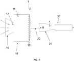
- the solar system 1 comprises three main parts: a solar receiver 10, a high temperature chamber 30, and fluid injection means 20 from the solar receiver 10 to the high temperature chamber 30.
- high temperatures correspond to temperatures that can almost only be achieved through a combustion flame or plasma, and not through simple electrical resistors. These high temperatures are typically above 1000 ° C, and may optionally reach 2000 ° C or 2500 ° C.
- the solar receiver is exposed to concentrated solar radiation.
- concentration of solar radiation is meant the focusing on a small surface of the solar radiation received by a large area using optical systems: field of mirrors (heliostats), large parabolic mirror, lenses, etc.
- the energy received by the receiver 10 is then equal to the total solar energy incident on the optical losses, for example the energy captured by the total surface of the heliostatic field 2 in the figure 1 .
- a coolant f circulates in the receiver 10, this fluid being heated to high temperature under the effect of concentrated solar radiation.
- Different types of fluids and different receiver geometries will be described in detail below.
- the high temperature chamber 30 is in turn the location of a high temperature industrial process.
- many industrial processes can be implemented within the scope of the present invention, in particular any process requiring a contribution of volumic energy, and especially if this contribution is generally made thanks to a combustion flame.
- the heart of the invention lies in the injection, via the injection means 20, of the coolant f in the form of a gaseous jet g in the at least one high temperature chamber 30.
- a flame n It consists only of high-temperature products or intermediate products of the combustion reaction that generated it (usually CO2, H2O), the luminous appearance of the flame being due to the excitation of electrons of these gases .
- a gaseous jet at high temperature can therefore be equivalent to a combustion flame.
- the solar receiver 10 comprises a cavity 11, the cavity 11 being provided with an opening 12 transparent to concentrated solar radiation, and at least one solar absorption element 13 irradiated by the solar radiation concentrated through the opening 12.
- opening means any "window” that passes through solar radiation, whether glazed or a simple hole in the wall of the receiver 10.
- the opening 12 may be surrounded by a collector cone 16 (secondary concentrator) of reflective material, as seen on the figure 2 this cone making it possible to concentrate the concentrated solar radiation even more precisely towards the opening 12.
- the solar absorption elements 13 are refractory elements that will heat under the effect of concentrated solar radiation. It is at the level of their wall that solar energy is effectively transformed into heat.
- the first and second embodiments mentioned of the receiver 10 are differentiated by the shape of these elements 13 and the circulation diagram of the coolant f.
- the solar absorption element or elements 13 are thus advantageously channels and / or tubes lining at least one wall of the cavity 11, in particular the wall opposite the opening 12, that is to say the wall exposed to concentrated radiation.
- the coolant f circulates in the solar absorption elements 13, and it is heated to high temperature by thermal transfer in contact with the inner surface of the solar absorption elements 13.
- the channels and / or tubes may not not to be placed against a wall of the cavity 11, in order to indirectly receive the radiation by reflection on the walls of the cavity 11.
- the internal exchange surface between the tubes / channels and the coolant has when it interest to be as high as possible because the conducto-convective exchange coefficients at a solid-gas interface are low. It is also unnecessary to have large diameters of tubes / channels because the exchanges are only on the wall. Advantageously, one therefore multiplies the small diameter tubes / channels (see below for a description of a particularly preferred embodiment).
- the chosen materials are ultra-resistant materials at high temperatures (able to withstand for several hours 2000 ° C), but relatively heat conductors.
- the solar absorption elements 13 and more particularly the cavity 11 are therefore chosen from ceramic or graphite (sublimation point at 3652 ° C.). It is also possible to envisage tubes made of metallic materials with a high melting temperature, although graphite is preferred.
- the cavity 11 Since the heat transfer fluid f is sealed from the cavity 11 by the wall of the tubes, the cavity 11 most often does not need to be hermetic. It can be content with a simple hole as opening 12, but advantageously it is still equipped with a window to isolate the cavity 11 of the oxidizing atmosphere, harmful in particular to graphite. The cavity can then be filled with a neutral atmosphere (nitrogen or argon for example).
- a neutral atmosphere nitrogen or argon for example
- the coolant f directly in the cavity 11.
- the opening 12 is then obligatorily closed by a porthole 14 transparent to concentrated solar radiation, waterproof and resistant to pressure.
- the fluid f circulates around the thermal absorption elements 13, and not inside thereof. The fluid is thus brought to high temperature by thermal transfer in contact with the external surface of the solar absorption elements 13, always irradiated by the concentrated solar radiation through the opening 12. This solar receiver 10 is visible on the figure 4 .
- Preferred materials and dimensions are substantially the same as for the first embodiment.
- the cavity 11 and the opening 12 can be dispensed with.
- the solar receiver 10 is in fact traversed by a channel in which the coolant f is in motion, the heat transfer fluid f being carried at high temperature directly by heat transfer in contact with the inner surface of a channel wall whose outer surface is irradiated by concentrated solar radiation.
- the heat transfer fluid f being carried at high temperature directly by heat transfer in contact with the inner surface of a channel wall whose outer surface is irradiated by concentrated solar radiation.
- elements generating turbulence in this channel This solution is very similar to the first with integrated channels in the cavity, it should be known that at higher temperatures a cavity will be necessary to reduce heat losses by infrared radiation to the outside.
- Such a surface solar receiver channel is described in particular in the French patent application FR0957204 .
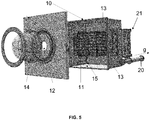
- FIG. figure 5 A particularly advantageous solar receiver 10 developed by the PROMES laboratory (CNRS Unit 8521), in accordance with the first embodiment of the receiver described above, is represented on FIG. figure 5 .
- This experimental multi-tubular receiver was able to heat a coolant f at a temperature of 2073 ° K.
- This receiver 10 consists of an aluminum envelope and a receiving cavity 11 in substantially cubic graphite (about 40 cm side).
- the opening 12 allowing the concentrated solar flux to enter has a diameter of 13 cm.
- the tubes 13, seven in number, are 800 mm long for an inside diameter of 18 mm and an outside diameter of 26 mm. They are staggered horizontally.
- a hemispherical quartz port 14 of 360 mm in diameter and 5 mm in thickness makes it possible to isolate the cavity 11 from the oxidizing atmosphere.
- the zone 15 (generally parallelepipedic, with a side of the order of 800 mm) surrounding the cavity 11 is filled with layers of insulating materials (for example fibrous materials in alumino-silicate or graphite felt) which help to maintain the heat. in the cavity 11.
- Fluid means a liquid or a gas input to the solar receiver 10, provided, however, that at high temperature levels reached at the output of the solar receiver 10 has reached the vaporization temperature so that the heat transfer fluid f can take the shape of a gaseous jet g.
- a gaseous fluid in the CNTPs normal conditions of pressure and temperatures
- dihydrogen in the absence of oxygen
- helium are particularly advantageous for their thermal performance and stability.
- the injection means 20 may comprise pump systems, but only extremely expensive and sophisticated systems can withstand the temperatures that prevail at the output of the solar receiver 10.
- the coolant f is injected under pressure in the solar receiver 10.
- the level pressure must be adjusted to the mechanical strength of the elements of the receiver, in particular the tubes 13 or the window 14 if there are any. It can nevertheless advantageously rise to several bars.
- the injection means 20 of the coolant f in the high temperature chamber 30 then advantageously consist of a simple pipe through which the heat transfer fluid f at high temperature escapes from the solar receiver 10 to the high temperature chamber 30 under the effect of the internal pressure in the solar receiver 10.
- the diameter of this pipe can be adjusted according to the pressure and the flow of fluid in the solar receiver so as to adjust the gas velocity at high temperature at the outlet of the pipe (d other words flame size simulated) optimal for the process.
- connection between the solar receiver 10 and the injection means 20 can advantageously be effected by means of a collector 21 as shown in FIG. figure 6 , especially if the solar receiver 10 is of tube / channel type 13. It is noted that a collector 21 is also present on the receiver of the figure 5 .
- the collector 21 allows a mixing zone to homogenize the temperature (the configuration of the cavity 11 can cause the tubes 13 do not receive all the same amount of energy) before introducing the fluid at high temperature into the chamber high temperature 30 via the injection means 20 (especially when these consist of a pipe).
- Graphite is a material adapted by its easy formatting and its temperature resistance.
- the hydrodynamics must particularly preferably favor high flow rates (between 0.3 and 0.8 Mach are desired in certain industrial processes) in order to ensure a turbulent regime and efficient particle transport . It goes without saying that the collector 21 must be closer to the solar receiver 10 to minimize heat loss.
- the pressure in the high temperature chamber 30 is advantageously less than the pressure in the solar receiver 10.
- the gaseous jet shape g is caused by the expansion of the heat transfer fluid f at the outlet of the injection means 20.
- relaxation, Joule-Thomson type is advantageously permitted by completing the driving by a simple nozzle.
- the injection means 20 then have an effect comparable to that of a nozzle. They increase the regularity of the gaseous jet, and facilitate the diffusion of its thermal energy in the high temperature chamber 30 for the needs of the process.
- zone 31 of the chamber 30 where the gas is injected advantageously has a relatively central position, so as to avoid heating the walls as much as possible.
- zone 31 corresponds to a premix zone (see below).
- the temperature of the heat transfer fluid f at high temperature is advantageously between 1000 ° C. and 2500 ° C. depending on the flame temperature required by the industrial process.
- the system according to the invention can be adapted to a large number of industrial processes. This adaptation requires the choice of a high temperature chamber 30 possibly specific to the desired process. It will be appreciated that the invention is not limited to any particular industrial process.
- a furnace can be chosen as a high temperature chamber 30, the high temperature industrial process being a process for obtaining metallic or ceramic material, such as decarburization.
- iron ore for the production of steel (chamber 30 is then a blast furnace), or the melting of silica for the production of glass.
- the high temperature chamber 30 may be a chemical reactor, and the high temperature industrial process an endothermic chemical reaction.
- the use of the solar system 1 according to the invention to implement endothermic chemical reactions is particularly interesting because of the possibility of choosing the coolant, that is to say the gas or gases that constitute the flame, unlike the case of combustions, where we always deal with the same gases (CO 2 , CO, NO x , SO x ). These are pollutants that intermingle with, among other things, the products of the reaction and contaminate them.
- the heat transfer fluid f advantageously comprises a chemically inert gas and / or a reagent of said endothermic chemical reaction and / or a product of said endothermic chemical reaction. It is therefore possible to have a perfectly controlled reaction.
- At least one reagent r of said endothermic chemical reaction may be injected into the high temperature reactor 30 at the aforementioned high temperature coolant injection zone 31.
- one can use one as heat transfer fluid, and inject the second into the zone 31. This gives a good mixture of which one of the reagents is already at a high level. 'energy.
- high temperature chamber 30a, 30b, etc. each being a chemical reactor, particularly in the case of complex reactions.
- These reactors can be advantageously mounted in series, the products of the n-th reactor being injected into the n + 1-th reactor.
- An advantageous embodiment would be to use B as heat transfer fluid, to provide an injection of A into the first reactor 30a and the third reactor 30c, and an injection of C into the second reactor 30b.
- the solar system 1 according to the invention is particularly suitable for industrial processes for producing hydrogen or carbon nanoparticles from gaseous precursors, often referred to as “furnace processes", or “baking processes” in French.
- the heat transfer fluid f is dihydrogen, the methane being injected into the high temperature reactor 30.
- the figure 7 represents a flow plan of fluids (Prosim® software) particularly illustrating the integration of the solar system 1 according to the invention in an industrial plant for the production of hydrogen and carbon blacks.
- the hydrogen is injected in the form of a gaseous jet at 1873 ° K.
- This hot gas is then mixed with methane in a high temperature adiabatic reactor, symbolized on the figure 7 by two high-temperature reactors 30a, 30b virtually consecutive: the cracking reaction comprises in fact two reaction stages (which for all that take place physically in the same reactor 30).
- the so-called methane coupling reaction is carried out.
- Two methane molecules "couple" in an acetylene molecule: CH 4 ⁇ 1 ⁇ 2 C 2 H 2 + 3/2 H 2 (reaction ratio 0.9).
- the acetylene is dissociated to hydrogen and carbon C 2 H 2 ⁇ H 2 + 2C (reaction rate 0.9).
- the process is constrained so that the outlet temperature of the reaction zone, measured via a sensor, is not lower than 900 ° C. (minimum temperature of the carbon black production process called "thermal black") by controlling the flow rate heat transfer H2 recirculation via the electronically controlled three-way valve 7.
- the flow of methane, injected at the inlet 8, is when fixed here at 400 kg / h.
- a heat exchanger 5 (“Multi Fluid Heat Exchanger") advantageously makes it possible to recover the heat of the products for the preheating of the reagent on the one hand and the gas to be heated on the other hand.
- 4b bag filters may be necessary for secondary filtration before purifying the products gaseous in a pressure swing adsorption column 6 (100% H 2 purity, 95% recovery rate). Beforehand, the gases must be compressed. Part of the purified hydrogen at column 6 is recirculated as heat transfer fluid f to the solar receiver 10 after preheating at the exchanger 5, the other part is recovered at the outlet 9c for recovery (production of 100 kg / h). The power required for the solar heating of hydrogen at the solar receiver 10 is 2.5 MW. The carbon blacks recovered at cyclone 4a (carbon outlet 9a) and at the level of filters 4b (release of carbon residues 9b) can then be conditioned (production of 300 kg / h).
- the invention relates to a method associated with the solar system according to the first aspect of the invention.
Claims (15)
- Solarsystem (1), das einen Volumenenergieeintrag gestattet, welcher die Wirkung einer Verbrennungsflamme für einen industriellen Hochtemperaturprozess reproduziert, enthaltend
einen Solarempfänger (10), der einer konzentrierten Sonnenstrahlung ausgesetzt wird,
dadurch gekennzeichnet, dass das Folgende enthält:ein (flüssiges oder gasförmiges) Wärmeträgermedium (f), das auf hohe Temperatur gebracht wird;zumindest eine Hochtemperaturkammer (30), in welcher der industrielle Hochtemperaturprozess erfolgt,Einspritzeinrichtungen (20) zum Einspritzen des Wärmeträgermediums (f) von dem Solarempfänger (10) in die Hochtemperaturkammer (30), wobei die Einspritzeinrichtungen (20) dazu angeordnet und ausgelegt sind, um das Wärmeträgermedium (f) in Form eines Gasstrahls (g) einzuspritzen, der die Wirkung einer Verbrennungsflamme in der zumindest einen Hochtemperaturkammer (30) reproduziert. - System nach Anspruch 1, wobei der Solarempfänger (10) einen Hohlraum (11) enthält, wobei der Hohlraum (11) mit einer Öffnung (12) versehen ist, die für konzentrierte Sonnenstrahlung durchlässig ist, sowie mit zumindest einem Solarabsorptionselement (13), das mit der konzentrierten Sonnenstrahlung durch die Öffnung (12) hindurch bestrahlt wird.
- System nach Anspruch 2, wobei das bzw. die Solarabsorptionselemente (13) Rohre und/oder Kanäle sind, die zumindest eine Wand des Hohlraums (11) auskleiden.
- System nach Anspruch 3, wobei das Wärmeträgermedium (f) in dem bzw. den Solarabsorptionselementen (13) strömt, wobei das Wärmeträgermedium (f) durch Wärmeübertragung in Kontakt mit der Innenfläche der Solarabsorptionselemente (13) auf eine hohe Temperatur gebracht wird.
- System nach einem der Ansprüche 2 oder 3, wobei das Wärmeträgermedium (f) in dem Hohlraum (11) strömt, wobei die Öffnung (12) von einem Sichtfenster (14) überdeckt ist, das für konzentrierte Sonnenstrahlung durchlässig und abgedichtet ist, wobei das Wärmeträgermedium (f) durch Wärmeübertragung in Kontakt mit der Außenfläche des bzw. der Solarabsorptionselemente (13) auf hohe Temperatur gebracht wird.
- System nach Anspruch 1, wobei der Solarempfänger (10) von einem Kanal durchsetzt wird, in welchem das Wärmeträgermedium (f) in Bewegung ist, wobei das Wärmeträgermedium (f) durch Wärmeübertragung in Kontakt mit der Innenfläche einer Wand des Kanals, dessen Außenfläche mit der konzentrierten Sonnenstrahlung bestrahlt wird, auf hohe Temperatur gebracht wird.
- System nach Anspruch nach einem der vorangehenden Ansprüche, wobei das Wärmeträgermedium (f) unter Druck in den Solarempfänger (10) eingespritzt wird.
- System nach Anspruch 7, wobei die Einspritzeinrichtungen (20) zum Einspritzen des Wärmeträgermediums (f) in die Hochtemperaturkammer (30) aus einer Leitung bestehen, über welche das Wärmeträgermedium (f) bei hoher Temperatur unter der Wirkung des Innendrucks in dem Solarempfänger (10) aus dem Solarempfänger (10) zur Hochtemperaturkammer (30) hin austritt.
- System nach Anspruch 8, wobei der Druck in der Hochtemperaturkammer (30) geringer als der Druck in dem Solarempfänger (10) ist, wobei die Form des Gasstrahls (g) durch das Entspannen des Wärmeträgermediums (f) am Auslass der Einspritzeinrichtungen (20) bewirkt wird.
- System nach einem der vorangehenden Ansprüche, wobei die Hochtemperaturkammer (30) ein Ofen ist und der industrielle Hochtemperaturprozess ein Verfahren zum Gewinnen eines metallischen oder keramischen Materials ist.
- System nach einem der vorangehenden Ansprüche, wobei die Hochtemperaturkammer (30) ein chemischer Reaktor ist und der industrielle Hochtemperaturprozess eine endotherme chemische Reaktion ist.
- System nach dem vorangehenden Anspruch, wobei das Wärmeträgermedium (f) ein chemisch inertes Gas und/oder ein Reagenz der endothermen chemischen Reaktion und/oder ein Produkt der endothermen chemischen Reaktion enthalt.
- System nach einem der Ansprüche 11 oder 12, wobei zumindest ein Reagenz (r) der endothermen chemischen Reaktion in den Hochtemperaturreaktor (30) in Höhe eines Einspritzbereichs (31) des Wärmeträgermediums (f) bei hoher Temperatur eingespritzt wird.
- System nach einem der Ansprüche 11 bis 13, enthaltend eine Mehrzahl von Hochtemperaturkammern (30a, 30b ...), die jeweils ein chemischer Reaktor sind, wobei die Produkte des n-ten Reaktors (30) in den n+1-ten Reaktor (30) eingespritzt werden.
- Verfahren zum Volumenenergieeintrag, welcher die Wirkung einer Verbrennungsflamme für einen industriellen Hochtemperaturprozess reproduziert, dadurch gekennzeichnet, dass es die Schritte umfasst:- Bestrahlen eines Solarempfängers (10), in welchem ein Wärmeträgermedium (f) strömt, mit konzentrierter Sonnenstrahlung, so dass das Wärmeträgermedium (f) auf eine hohe Temperatur gebracht wird;- Einspritzen des Wärmeträgermediums (f) von dem Solarempfänger (10) in eine Hochtemperaturkammer (30) in Form eines Gasstrahls (g), der die Wirkung einer Verbrennungsflamme reproduziert;- Durchführen des industriellen Prozesses bei hoher Temperatur in der Hochtemperaturkammer (30) unter der Wirkung der erzeugten Verbrennungsflamme.
Applications Claiming Priority (2)
| Application Number | Priority Date | Filing Date | Title |
|---|---|---|---|
| FR1152862A FR2973483B1 (fr) | 2011-04-04 | 2011-04-04 | Systeme solaire permettant de reproduire l'effet d'une flamme de combustion |
| PCT/EP2012/056129 WO2012136689A1 (fr) | 2011-04-04 | 2012-04-04 | Système solaire permettant de reproduire l'effet d'une flamme de combustion |
Publications (2)
| Publication Number | Publication Date |
|---|---|
| EP2694884A1 EP2694884A1 (de) | 2014-02-12 |
| EP2694884B1 true EP2694884B1 (de) | 2019-06-19 |
Family
ID=45926588
Family Applications (1)
| Application Number | Title | Priority Date | Filing Date |
|---|---|---|---|
| EP12711670.5A Active EP2694884B1 (de) | 2011-04-04 | 2012-04-04 | Solarsystem zur reproduktion der wirkung einer verbrennungsflamme |
Country Status (9)
| Country | Link |
|---|---|
| US (1) | US9784473B2 (de) |
| EP (1) | EP2694884B1 (de) |
| CN (1) | CN103534537B (de) |
| ES (1) | ES2745148T3 (de) |
| FR (1) | FR2973483B1 (de) |
| IL (1) | IL228748B (de) |
| MA (1) | MA35060B1 (de) |
| WO (1) | WO2012136689A1 (de) |
| ZA (1) | ZA201307497B (de) |
Families Citing this family (3)
| Publication number | Priority date | Publication date | Assignee | Title |
|---|---|---|---|---|
| ES2525196B1 (es) * | 2013-04-29 | 2016-02-26 | Termo Fluids, S.L. | Receptor solar de torre tubular aislado a las pérdidas energéticas por radiación |
| CN104474993B (zh) * | 2014-11-13 | 2016-03-09 | 哈尔滨工业大学(威海) | 悬浮粒子系太阳能热化学反应器 |
| CN105546852B (zh) * | 2016-01-28 | 2017-06-27 | 西安交通大学 | 一种太阳能吸热器壁面热流密度均匀化装置及方法 |
Family Cites Families (5)
| Publication number | Priority date | Publication date | Assignee | Title |
|---|---|---|---|---|
| FR957204A (de) | 1950-02-17 | |||
| US4164123A (en) * | 1976-08-25 | 1979-08-14 | Smith Otto J M | Solar thermal electric power plant |
| CN1143729C (zh) * | 1995-03-20 | 2004-03-31 | 迈克尔·L·策特纳 | 可流动化合物实现热化学转化的方法和实现这种方法的转化器 |
| US6872378B2 (en) * | 2000-05-08 | 2005-03-29 | Midwest Research Institute | Solar thermal aerosol flow reaction process |
| US9150803B2 (en) * | 2009-06-09 | 2015-10-06 | Sundrop Fuels, Inc. | Systems and methods for biomass grinding and feeding |
-
2011
- 2011-04-04 FR FR1152862A patent/FR2973483B1/fr active Active
-
2012
- 2012-04-04 US US14/009,868 patent/US9784473B2/en active Active
- 2012-04-04 EP EP12711670.5A patent/EP2694884B1/de active Active
- 2012-04-04 CN CN201280021204.2A patent/CN103534537B/zh active Active
- 2012-04-04 ES ES12711670T patent/ES2745148T3/es active Active
- 2012-04-04 WO PCT/EP2012/056129 patent/WO2012136689A1/fr active Application Filing
- 2012-04-04 MA MA36355A patent/MA35060B1/fr unknown
-
2013
- 2013-10-06 IL IL228748A patent/IL228748B/en active IP Right Grant
- 2013-10-08 ZA ZA2013/07497A patent/ZA201307497B/en unknown
Non-Patent Citations (1)
| Title |
|---|
| None * |
Also Published As
| Publication number | Publication date |
|---|---|
| EP2694884A1 (de) | 2014-02-12 |
| ES2745148T3 (es) | 2020-02-27 |
| WO2012136689A1 (fr) | 2012-10-11 |
| IL228748B (en) | 2018-10-31 |
| FR2973483A1 (fr) | 2012-10-05 |
| CN103534537B (zh) | 2016-10-12 |
| US9784473B2 (en) | 2017-10-10 |
| MA35060B1 (fr) | 2014-04-03 |
| ZA201307497B (en) | 2014-09-25 |
| CN103534537A (zh) | 2014-01-22 |
| US20140083415A1 (en) | 2014-03-27 |
| FR2973483B1 (fr) | 2013-04-26 |
| IL228748A0 (en) | 2013-12-31 |
Similar Documents
| Publication | Publication Date | Title |
|---|---|---|
| ES2368813T3 (es) | Procedimiento que utiliza energía térmica solar acoplada a plasmas para producir un carburante líquido e hidrógeno a partir de biomasa de carbón fósil (procedimiento p-sl y p-sh). | |
| CA2645784C (fr) | Reacteur echangeur a combustion interne pour reaction endothermique en lit fixe | |
| EP0666104B1 (de) | Vorrichtung zur Durchführung von chemischen Reaktionen welche, mindestens während des Startens, eine Zufuhr von Kalorien nötig haben | |
| EP2038210B1 (de) | Reaktor mit einem wärmegradienten, der zur produktion von reinem wasserstoff gesteuert wird | |
| FR2726070A1 (fr) | Appareil de chauffage de fluide a bruleur de surface et a matrice poreuse | |
| EP2694884B1 (de) | Solarsystem zur reproduktion der wirkung einer verbrennungsflamme | |
| EP2394735A1 (de) | Wechselreaktor mit Bajonettrohren und Rauchrohren, die am oberen Deckengewölbe des Reaktors aufgehängt sind | |
| EP3087040A1 (de) | Verbrennungsverfahren und anlage mit optimierter energierückgewinnung | |
| EP1766289A1 (de) | Homogenes verbrennungsverfahren und thermogenerator damit | |
| FR3015636A1 (fr) | Combustion avec recuperation de chaleur amelioree | |
| FR2494256A1 (fr) | Decomposeur de so3 a cartouche catalytique pour la production thermochimique de l'hydrogene | |
| WO2016116450A2 (fr) | Module de combustion offrant une combustion des gaz amelioree | |
| EP1883603A2 (de) | Vorrichtung mit einer reaktionskammer, in die vorerhitzte fliessfähige reagenzien zur erzeugung einer hochtemperaturreaktion eingetragen werden | |
| BE1006702A6 (fr) | Dispositif de rechauffage d'un fluide gazeux. | |
| EP3048367B1 (de) | Verbrennungsmodul, das eine deutlich einheitliche temperatur aufweist | |
| FR2898517A1 (fr) | Reacteur echangeur a combustion interne pour reaction endothermique en lit fixe | |
| FR2828731A1 (fr) | Installation de conversion chimique d'une charge presentant une surface reduite d'echange de chaleur | |
| FR3075331A1 (fr) | Concentrateur d'energie solaire | |
| CA3142845A1 (fr) | Dispositif d'hyper concentration et transport d'energie solaire distant par fibre optique associe a un procede de production d'un melange h2/o2 par thermophotolyse | |
| FR3097304A1 (fr) | Absorbeur hybride de rayonnements pour centrale solaire, et procede de preparation d’un tel absorbeur | |
| EP3048384B1 (de) | Verbrennungssystem mit verbesserter temperaturbeständigkeit |
Legal Events
| Date | Code | Title | Description |
|---|---|---|---|
| PUAI | Public reference made under article 153(3) epc to a published international application that has entered the european phase |
Free format text: ORIGINAL CODE: 0009012 |
|
| 17P | Request for examination filed |
Effective date: 20131024 |
|
| AK | Designated contracting states |
Kind code of ref document: A1 Designated state(s): AL AT BE BG CH CY CZ DE DK EE ES FI FR GB GR HR HU IE IS IT LI LT LU LV MC MK MT NL NO PL PT RO RS SE SI SK SM TR |
|
| DAX | Request for extension of the european patent (deleted) | ||
| STAA | Information on the status of an ep patent application or granted ep patent |
Free format text: STATUS: EXAMINATION IS IN PROGRESS |
|
| 17Q | First examination report despatched |
Effective date: 20171109 |
|
| REG | Reference to a national code |
Ref country code: DE Ref legal event code: R079 Ref document number: 602012061132 Country of ref document: DE Free format text: PREVIOUS MAIN CLASS: F24J0002070000 Ipc: F24S0020200000 |
|
| GRAP | Despatch of communication of intention to grant a patent |
Free format text: ORIGINAL CODE: EPIDOSNIGR1 |
|
| STAA | Information on the status of an ep patent application or granted ep patent |
Free format text: STATUS: GRANT OF PATENT IS INTENDED |
|
| RIC1 | Information provided on ipc code assigned before grant |
Ipc: B01J 19/12 20060101ALI20180906BHEP Ipc: F24S 20/20 20180101AFI20180906BHEP Ipc: B01J 12/00 20060101ALI20180906BHEP Ipc: F24S 10/70 20180101ALI20180906BHEP |
|
| INTG | Intention to grant announced |
Effective date: 20181005 |
|
| GRAJ | Information related to disapproval of communication of intention to grant by the applicant or resumption of examination proceedings by the epo deleted |
Free format text: ORIGINAL CODE: EPIDOSDIGR1 |
|
| STAA | Information on the status of an ep patent application or granted ep patent |
Free format text: STATUS: EXAMINATION IS IN PROGRESS |
|
| GRAP | Despatch of communication of intention to grant a patent |
Free format text: ORIGINAL CODE: EPIDOSNIGR1 |
|
| STAA | Information on the status of an ep patent application or granted ep patent |
Free format text: STATUS: GRANT OF PATENT IS INTENDED |
|
| INTC | Intention to grant announced (deleted) | ||
| INTG | Intention to grant announced |
Effective date: 20190219 |
|
| GRAS | Grant fee paid |
Free format text: ORIGINAL CODE: EPIDOSNIGR3 |
|
| GRAA | (expected) grant |
Free format text: ORIGINAL CODE: 0009210 |
|
| STAA | Information on the status of an ep patent application or granted ep patent |
Free format text: STATUS: THE PATENT HAS BEEN GRANTED |
|
| AK | Designated contracting states |
Kind code of ref document: B1 Designated state(s): AL AT BE BG CH CY CZ DE DK EE ES FI FR GB GR HR HU IE IS IT LI LT LU LV MC MK MT NL NO PL PT RO RS SE SI SK SM TR |
|
| REG | Reference to a national code |
Ref country code: GB Ref legal event code: FG4D Free format text: NOT ENGLISH |
|
| REG | Reference to a national code |
Ref country code: CH Ref legal event code: EP |
|
| REG | Reference to a national code |
Ref country code: IE Ref legal event code: FG4D Free format text: LANGUAGE OF EP DOCUMENT: FRENCH |
|
| REG | Reference to a national code |
Ref country code: DE Ref legal event code: R096 Ref document number: 602012061132 Country of ref document: DE |
|
| REG | Reference to a national code |
Ref country code: AT Ref legal event code: REF Ref document number: 1146033 Country of ref document: AT Kind code of ref document: T Effective date: 20190715 |
|
| REG | Reference to a national code |
Ref country code: CH Ref legal event code: NV Representative=s name: DENNEMEYER AG, CH |
|
| REG | Reference to a national code |
Ref country code: NL Ref legal event code: MP Effective date: 20190619 |
|
| PG25 | Lapsed in a contracting state [announced via postgrant information from national office to epo] |
Ref country code: HR Free format text: LAPSE BECAUSE OF FAILURE TO SUBMIT A TRANSLATION OF THE DESCRIPTION OR TO PAY THE FEE WITHIN THE PRESCRIBED TIME-LIMIT Effective date: 20190619 Ref country code: SE Free format text: LAPSE BECAUSE OF FAILURE TO SUBMIT A TRANSLATION OF THE DESCRIPTION OR TO PAY THE FEE WITHIN THE PRESCRIBED TIME-LIMIT Effective date: 20190619 Ref country code: FI Free format text: LAPSE BECAUSE OF FAILURE TO SUBMIT A TRANSLATION OF THE DESCRIPTION OR TO PAY THE FEE WITHIN THE PRESCRIBED TIME-LIMIT Effective date: 20190619 Ref country code: NO Free format text: LAPSE BECAUSE OF FAILURE TO SUBMIT A TRANSLATION OF THE DESCRIPTION OR TO PAY THE FEE WITHIN THE PRESCRIBED TIME-LIMIT Effective date: 20190919 Ref country code: AL Free format text: LAPSE BECAUSE OF FAILURE TO SUBMIT A TRANSLATION OF THE DESCRIPTION OR TO PAY THE FEE WITHIN THE PRESCRIBED TIME-LIMIT Effective date: 20190619 Ref country code: LT Free format text: LAPSE BECAUSE OF FAILURE TO SUBMIT A TRANSLATION OF THE DESCRIPTION OR TO PAY THE FEE WITHIN THE PRESCRIBED TIME-LIMIT Effective date: 20190619 |
|
| REG | Reference to a national code |
Ref country code: LT Ref legal event code: MG4D |
|
| PG25 | Lapsed in a contracting state [announced via postgrant information from national office to epo] |
Ref country code: BG Free format text: LAPSE BECAUSE OF FAILURE TO SUBMIT A TRANSLATION OF THE DESCRIPTION OR TO PAY THE FEE WITHIN THE PRESCRIBED TIME-LIMIT Effective date: 20190919 Ref country code: GR Free format text: LAPSE BECAUSE OF FAILURE TO SUBMIT A TRANSLATION OF THE DESCRIPTION OR TO PAY THE FEE WITHIN THE PRESCRIBED TIME-LIMIT Effective date: 20190920 Ref country code: RS Free format text: LAPSE BECAUSE OF FAILURE TO SUBMIT A TRANSLATION OF THE DESCRIPTION OR TO PAY THE FEE WITHIN THE PRESCRIBED TIME-LIMIT Effective date: 20190619 Ref country code: LV Free format text: LAPSE BECAUSE OF FAILURE TO SUBMIT A TRANSLATION OF THE DESCRIPTION OR TO PAY THE FEE WITHIN THE PRESCRIBED TIME-LIMIT Effective date: 20190619 |
|
| REG | Reference to a national code |
Ref country code: AT Ref legal event code: MK05 Ref document number: 1146033 Country of ref document: AT Kind code of ref document: T Effective date: 20190619 |
|
| PG25 | Lapsed in a contracting state [announced via postgrant information from national office to epo] |
Ref country code: EE Free format text: LAPSE BECAUSE OF FAILURE TO SUBMIT A TRANSLATION OF THE DESCRIPTION OR TO PAY THE FEE WITHIN THE PRESCRIBED TIME-LIMIT Effective date: 20190619 Ref country code: PT Free format text: LAPSE BECAUSE OF FAILURE TO SUBMIT A TRANSLATION OF THE DESCRIPTION OR TO PAY THE FEE WITHIN THE PRESCRIBED TIME-LIMIT Effective date: 20191021 Ref country code: NL Free format text: LAPSE BECAUSE OF FAILURE TO SUBMIT A TRANSLATION OF THE DESCRIPTION OR TO PAY THE FEE WITHIN THE PRESCRIBED TIME-LIMIT Effective date: 20190619 Ref country code: AT Free format text: LAPSE BECAUSE OF FAILURE TO SUBMIT A TRANSLATION OF THE DESCRIPTION OR TO PAY THE FEE WITHIN THE PRESCRIBED TIME-LIMIT Effective date: 20190619 Ref country code: RO Free format text: LAPSE BECAUSE OF FAILURE TO SUBMIT A TRANSLATION OF THE DESCRIPTION OR TO PAY THE FEE WITHIN THE PRESCRIBED TIME-LIMIT Effective date: 20190619 Ref country code: CZ Free format text: LAPSE BECAUSE OF FAILURE TO SUBMIT A TRANSLATION OF THE DESCRIPTION OR TO PAY THE FEE WITHIN THE PRESCRIBED TIME-LIMIT Effective date: 20190619 Ref country code: SK Free format text: LAPSE BECAUSE OF FAILURE TO SUBMIT A TRANSLATION OF THE DESCRIPTION OR TO PAY THE FEE WITHIN THE PRESCRIBED TIME-LIMIT Effective date: 20190619 |
|
| REG | Reference to a national code |
Ref country code: ES Ref legal event code: FG2A Ref document number: 2745148 Country of ref document: ES Kind code of ref document: T3 Effective date: 20200227 |
|
| PG25 | Lapsed in a contracting state [announced via postgrant information from national office to epo] |
Ref country code: IS Free format text: LAPSE BECAUSE OF FAILURE TO SUBMIT A TRANSLATION OF THE DESCRIPTION OR TO PAY THE FEE WITHIN THE PRESCRIBED TIME-LIMIT Effective date: 20191019 Ref country code: SM Free format text: LAPSE BECAUSE OF FAILURE TO SUBMIT A TRANSLATION OF THE DESCRIPTION OR TO PAY THE FEE WITHIN THE PRESCRIBED TIME-LIMIT Effective date: 20190619 |
|
| PG25 | Lapsed in a contracting state [announced via postgrant information from national office to epo] |
Ref country code: TR Free format text: LAPSE BECAUSE OF FAILURE TO SUBMIT A TRANSLATION OF THE DESCRIPTION OR TO PAY THE FEE WITHIN THE PRESCRIBED TIME-LIMIT Effective date: 20190619 |
|
| PG25 | Lapsed in a contracting state [announced via postgrant information from national office to epo] |
Ref country code: DK Free format text: LAPSE BECAUSE OF FAILURE TO SUBMIT A TRANSLATION OF THE DESCRIPTION OR TO PAY THE FEE WITHIN THE PRESCRIBED TIME-LIMIT Effective date: 20190619 Ref country code: PL Free format text: LAPSE BECAUSE OF FAILURE TO SUBMIT A TRANSLATION OF THE DESCRIPTION OR TO PAY THE FEE WITHIN THE PRESCRIBED TIME-LIMIT Effective date: 20190619 |
|
| PG25 | Lapsed in a contracting state [announced via postgrant information from national office to epo] |
Ref country code: IS Free format text: LAPSE BECAUSE OF FAILURE TO SUBMIT A TRANSLATION OF THE DESCRIPTION OR TO PAY THE FEE WITHIN THE PRESCRIBED TIME-LIMIT Effective date: 20200224 |
|
| REG | Reference to a national code |
Ref country code: DE Ref legal event code: R097 Ref document number: 602012061132 Country of ref document: DE |
|
| PLBE | No opposition filed within time limit |
Free format text: ORIGINAL CODE: 0009261 |
|
| STAA | Information on the status of an ep patent application or granted ep patent |
Free format text: STATUS: NO OPPOSITION FILED WITHIN TIME LIMIT |
|
| PG2D | Information on lapse in contracting state deleted |
Ref country code: IS |
|
| 26N | No opposition filed |
Effective date: 20200603 |
|
| PG25 | Lapsed in a contracting state [announced via postgrant information from national office to epo] |
Ref country code: SI Free format text: LAPSE BECAUSE OF FAILURE TO SUBMIT A TRANSLATION OF THE DESCRIPTION OR TO PAY THE FEE WITHIN THE PRESCRIBED TIME-LIMIT Effective date: 20190619 |
|
| PG25 | Lapsed in a contracting state [announced via postgrant information from national office to epo] |
Ref country code: MC Free format text: LAPSE BECAUSE OF FAILURE TO SUBMIT A TRANSLATION OF THE DESCRIPTION OR TO PAY THE FEE WITHIN THE PRESCRIBED TIME-LIMIT Effective date: 20190619 |
|
| PG25 | Lapsed in a contracting state [announced via postgrant information from national office to epo] |
Ref country code: LU Free format text: LAPSE BECAUSE OF NON-PAYMENT OF DUE FEES Effective date: 20200404 |
|
| REG | Reference to a national code |
Ref country code: BE Ref legal event code: MM Effective date: 20200430 |
|
| PG25 | Lapsed in a contracting state [announced via postgrant information from national office to epo] |
Ref country code: BE Free format text: LAPSE BECAUSE OF NON-PAYMENT OF DUE FEES Effective date: 20200430 |
|
| GBPC | Gb: european patent ceased through non-payment of renewal fee |
Effective date: 20200404 |
|
| PG25 | Lapsed in a contracting state [announced via postgrant information from national office to epo] |
Ref country code: GB Free format text: LAPSE BECAUSE OF NON-PAYMENT OF DUE FEES Effective date: 20200404 Ref country code: IE Free format text: LAPSE BECAUSE OF NON-PAYMENT OF DUE FEES Effective date: 20200404 |
|
| PG25 | Lapsed in a contracting state [announced via postgrant information from national office to epo] |
Ref country code: MT Free format text: LAPSE BECAUSE OF FAILURE TO SUBMIT A TRANSLATION OF THE DESCRIPTION OR TO PAY THE FEE WITHIN THE PRESCRIBED TIME-LIMIT Effective date: 20190619 Ref country code: CY Free format text: LAPSE BECAUSE OF FAILURE TO SUBMIT A TRANSLATION OF THE DESCRIPTION OR TO PAY THE FEE WITHIN THE PRESCRIBED TIME-LIMIT Effective date: 20190619 |
|
| PG25 | Lapsed in a contracting state [announced via postgrant information from national office to epo] |
Ref country code: MK Free format text: LAPSE BECAUSE OF FAILURE TO SUBMIT A TRANSLATION OF THE DESCRIPTION OR TO PAY THE FEE WITHIN THE PRESCRIBED TIME-LIMIT Effective date: 20190619 |
|
| PG25 | Lapsed in a contracting state [announced via postgrant information from national office to epo] |
Ref country code: IT Free format text: LAPSE BECAUSE OF NON-PAYMENT OF DUE FEES Effective date: 20220404 |
|
| PGFP | Annual fee paid to national office [announced via postgrant information from national office to epo] |
Ref country code: IT Payment date: 20230417 Year of fee payment: 12 Ref country code: FR Payment date: 20230425 Year of fee payment: 12 Ref country code: ES Payment date: 20230504 Year of fee payment: 12 Ref country code: DE Payment date: 20230412 Year of fee payment: 12 Ref country code: CH Payment date: 20230502 Year of fee payment: 12 |