EP2694884B1 - Solar system for reproducing the effect of a combustion flame - Google Patents
Solar system for reproducing the effect of a combustion flame Download PDFInfo
- Publication number
- EP2694884B1 EP2694884B1 EP12711670.5A EP12711670A EP2694884B1 EP 2694884 B1 EP2694884 B1 EP 2694884B1 EP 12711670 A EP12711670 A EP 12711670A EP 2694884 B1 EP2694884 B1 EP 2694884B1
- Authority
- EP
- European Patent Office
- Prior art keywords
- heat transfer
- solar
- transfer fluid
- temperature
- receiver
- Prior art date
- Legal status (The legal status is an assumption and is not a legal conclusion. Google has not performed a legal analysis and makes no representation as to the accuracy of the status listed.)
- Active
Links
Images


Classifications
-
- F—MECHANICAL ENGINEERING; LIGHTING; HEATING; WEAPONS; BLASTING
- F24—HEATING; RANGES; VENTILATING
- F24S—SOLAR HEAT COLLECTORS; SOLAR HEAT SYSTEMS
- F24S20/00—Solar heat collectors specially adapted for particular uses or environments
- F24S20/20—Solar heat collectors for receiving concentrated solar energy, e.g. receivers for solar power plants
-
- F—MECHANICAL ENGINEERING; LIGHTING; HEATING; WEAPONS; BLASTING
- F24—HEATING; RANGES; VENTILATING
- F24S—SOLAR HEAT COLLECTORS; SOLAR HEAT SYSTEMS
- F24S10/00—Solar heat collectors using working fluids
- F24S10/70—Solar heat collectors using working fluids the working fluids being conveyed through tubular absorbing conduits
-
- F—MECHANICAL ENGINEERING; LIGHTING; HEATING; WEAPONS; BLASTING
- F24—HEATING; RANGES; VENTILATING
- F24S—SOLAR HEAT COLLECTORS; SOLAR HEAT SYSTEMS
- F24S23/00—Arrangements for concentrating solar-rays for solar heat collectors
- F24S23/70—Arrangements for concentrating solar-rays for solar heat collectors with reflectors
-
- Y—GENERAL TAGGING OF NEW TECHNOLOGICAL DEVELOPMENTS; GENERAL TAGGING OF CROSS-SECTIONAL TECHNOLOGIES SPANNING OVER SEVERAL SECTIONS OF THE IPC; TECHNICAL SUBJECTS COVERED BY FORMER USPC CROSS-REFERENCE ART COLLECTIONS [XRACs] AND DIGESTS
- Y02—TECHNOLOGIES OR APPLICATIONS FOR MITIGATION OR ADAPTATION AGAINST CLIMATE CHANGE
- Y02E—REDUCTION OF GREENHOUSE GAS [GHG] EMISSIONS, RELATED TO ENERGY GENERATION, TRANSMISSION OR DISTRIBUTION
- Y02E10/00—Energy generation through renewable energy sources
- Y02E10/40—Solar thermal energy, e.g. solar towers
- Y02E10/44—Heat exchange systems
-
- Y—GENERAL TAGGING OF NEW TECHNOLOGICAL DEVELOPMENTS; GENERAL TAGGING OF CROSS-SECTIONAL TECHNOLOGIES SPANNING OVER SEVERAL SECTIONS OF THE IPC; TECHNICAL SUBJECTS COVERED BY FORMER USPC CROSS-REFERENCE ART COLLECTIONS [XRACs] AND DIGESTS
- Y02—TECHNOLOGIES OR APPLICATIONS FOR MITIGATION OR ADAPTATION AGAINST CLIMATE CHANGE
- Y02P—CLIMATE CHANGE MITIGATION TECHNOLOGIES IN THE PRODUCTION OR PROCESSING OF GOODS
- Y02P80/00—Climate change mitigation technologies for sector-wide applications
- Y02P80/20—Climate change mitigation technologies for sector-wide applications using renewable energy
Definitions
- the present invention relates to the field of solar thermal and thermochemical systems at high temperature.
- combustion flame is, with the plasma process, one of the only ways to obtain a heat input in a volume at the industrial level. Also referred to as “flame temperatures” are the temperatures to which these processes are subjected.
- combustion flame that can be obtained only from renewable energy, and in particular solar energy.
- the so-called concentrated solar systems allow the conversion of solar radiation into thermal energy, which is generally used for the production of electricity.
- a concentrating system is the tower plant.
- Such a system consists of a tower and a field of moving mirrors called heliostats which concentrates the radiation on a reduced area at the top of the tower.
- This area illuminated by the concentrated radiation receives several hundred times the direct solar radiation, and is equipped with a device called solar receiver whose function is to transmit this energy to a fluid (a liquid or a gas) circulating therein, typically turbined water vapor to produce electricity.
- a fluid typically turbined water vapor to produce electricity.
- FIG 1 a tower thermodynamic power plant comprising a tower 3, a heliostatic field 2, and the solar receiver 10.
- the solar receiver described in the patent application US 2010/0237291 consists of a cavity traversed by a plurality of tubes in which chemical compounds circulate which can react in so-called endothermic reactions, that is to say requiring high temperatures usually used under the effect of a combustion flame (cracking of methane for example).
- the outer wall of the tubes receives concentrated solar radiation, which carries it at high temperature: the tubes act as a transfer wall.
- the thermal input is not volume but surface: the heat is transferred to the chemical reagents by contact with the inner wall of the tubes. This surface thermal contribution poorly reproduces the effect of a combustion flame, since the chemical reaction takes place mainly at the level of the walls. This decreases the yield and leads to the appearance and growth of solid residue deposits on the walls (in this case pure carbon in the case of a cracking process), which quickly makes the unusable receiver: the deposits reduce the heat input and obstruct the tubes.
- the international patent application WO 03/049853 proposes a sealed solar receiver (a porthole makes it possible to let in the concentrated solar radiation), in which the chemical compounds to be heated circulate directly.
- a cloud of absorbent solid microparticles carbon black smoke, for example
- the thermal input is this time volumic (rigorously, the heat exchange takes place on the surface of the particles, but by the relatively uniform diffusion of the particles in the volume, it is comparable to a thermal contribution volume), and reproduces better the effect of a combustion flame.
- the performance of this type of solar receiver is very limited: indeed, the particles quickly tend to settle on the window and opacify. Recovering the products of the reaction is also complex because it is necessary to filter the gases obtained to isolate and recover the microparticles without contaminating the products. Industrial interest is therefore weak.
- the present invention thus relates to a solar system allowing a contribution of volumic energy reproducing the effect of a combustion flame for a high temperature industrial process, comprising a solar receiver exposed to concentrated solar radiation, characterized in that it comprises a fluid (liquid or gaseous) coolant heated to high temperature; at least one high temperature chamber in which is implemented said high temperature industrial process; means for injecting the coolant from the solar receiver to the high temperature chamber, the injection means being arranged and configured to inject the heat transfer fluid in the form of a jet of gas reproducing the effect of a combustion flame in the at least one high temperature chamber.
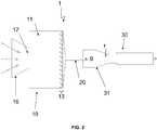
- the solar system 1 comprises three main parts: a solar receiver 10, a high temperature chamber 30, and fluid injection means 20 from the solar receiver 10 to the high temperature chamber 30.
- high temperatures correspond to temperatures that can almost only be achieved through a combustion flame or plasma, and not through simple electrical resistors. These high temperatures are typically above 1000 ° C, and may optionally reach 2000 ° C or 2500 ° C.
- the solar receiver is exposed to concentrated solar radiation.
- concentration of solar radiation is meant the focusing on a small surface of the solar radiation received by a large area using optical systems: field of mirrors (heliostats), large parabolic mirror, lenses, etc.
- the energy received by the receiver 10 is then equal to the total solar energy incident on the optical losses, for example the energy captured by the total surface of the heliostatic field 2 in the figure 1 .
- a coolant f circulates in the receiver 10, this fluid being heated to high temperature under the effect of concentrated solar radiation.
- Different types of fluids and different receiver geometries will be described in detail below.
- the high temperature chamber 30 is in turn the location of a high temperature industrial process.
- many industrial processes can be implemented within the scope of the present invention, in particular any process requiring a contribution of volumic energy, and especially if this contribution is generally made thanks to a combustion flame.
- the heart of the invention lies in the injection, via the injection means 20, of the coolant f in the form of a gaseous jet g in the at least one high temperature chamber 30.
- a flame n It consists only of high-temperature products or intermediate products of the combustion reaction that generated it (usually CO2, H2O), the luminous appearance of the flame being due to the excitation of electrons of these gases .
- a gaseous jet at high temperature can therefore be equivalent to a combustion flame.
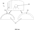
- the solar receiver 10 comprises a cavity 11, the cavity 11 being provided with an opening 12 transparent to concentrated solar radiation, and at least one solar absorption element 13 irradiated by the solar radiation concentrated through the opening 12.
- opening means any "window” that passes through solar radiation, whether glazed or a simple hole in the wall of the receiver 10.
- the opening 12 may be surrounded by a collector cone 16 (secondary concentrator) of reflective material, as seen on the figure 2 this cone making it possible to concentrate the concentrated solar radiation even more precisely towards the opening 12.
- the solar absorption elements 13 are refractory elements that will heat under the effect of concentrated solar radiation. It is at the level of their wall that solar energy is effectively transformed into heat.
- the first and second embodiments mentioned of the receiver 10 are differentiated by the shape of these elements 13 and the circulation diagram of the coolant f.
- the solar absorption element or elements 13 are thus advantageously channels and / or tubes lining at least one wall of the cavity 11, in particular the wall opposite the opening 12, that is to say the wall exposed to concentrated radiation.
- the coolant f circulates in the solar absorption elements 13, and it is heated to high temperature by thermal transfer in contact with the inner surface of the solar absorption elements 13.
- the channels and / or tubes may not not to be placed against a wall of the cavity 11, in order to indirectly receive the radiation by reflection on the walls of the cavity 11.
- the internal exchange surface between the tubes / channels and the coolant has when it interest to be as high as possible because the conducto-convective exchange coefficients at a solid-gas interface are low. It is also unnecessary to have large diameters of tubes / channels because the exchanges are only on the wall. Advantageously, one therefore multiplies the small diameter tubes / channels (see below for a description of a particularly preferred embodiment).
- the chosen materials are ultra-resistant materials at high temperatures (able to withstand for several hours 2000 ° C), but relatively heat conductors.
- the solar absorption elements 13 and more particularly the cavity 11 are therefore chosen from ceramic or graphite (sublimation point at 3652 ° C.). It is also possible to envisage tubes made of metallic materials with a high melting temperature, although graphite is preferred.
- the cavity 11 Since the heat transfer fluid f is sealed from the cavity 11 by the wall of the tubes, the cavity 11 most often does not need to be hermetic. It can be content with a simple hole as opening 12, but advantageously it is still equipped with a window to isolate the cavity 11 of the oxidizing atmosphere, harmful in particular to graphite. The cavity can then be filled with a neutral atmosphere (nitrogen or argon for example).
- a neutral atmosphere nitrogen or argon for example
- the coolant f directly in the cavity 11.
- the opening 12 is then obligatorily closed by a porthole 14 transparent to concentrated solar radiation, waterproof and resistant to pressure.
- the fluid f circulates around the thermal absorption elements 13, and not inside thereof. The fluid is thus brought to high temperature by thermal transfer in contact with the external surface of the solar absorption elements 13, always irradiated by the concentrated solar radiation through the opening 12. This solar receiver 10 is visible on the figure 4 .
- Preferred materials and dimensions are substantially the same as for the first embodiment.
- the cavity 11 and the opening 12 can be dispensed with.
- the solar receiver 10 is in fact traversed by a channel in which the coolant f is in motion, the heat transfer fluid f being carried at high temperature directly by heat transfer in contact with the inner surface of a channel wall whose outer surface is irradiated by concentrated solar radiation.
- the heat transfer fluid f being carried at high temperature directly by heat transfer in contact with the inner surface of a channel wall whose outer surface is irradiated by concentrated solar radiation.
- elements generating turbulence in this channel This solution is very similar to the first with integrated channels in the cavity, it should be known that at higher temperatures a cavity will be necessary to reduce heat losses by infrared radiation to the outside.
- Such a surface solar receiver channel is described in particular in the French patent application FR0957204 .
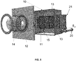
- FIG. figure 5 A particularly advantageous solar receiver 10 developed by the PROMES laboratory (CNRS Unit 8521), in accordance with the first embodiment of the receiver described above, is represented on FIG. figure 5 .
- This experimental multi-tubular receiver was able to heat a coolant f at a temperature of 2073 ° K.
- This receiver 10 consists of an aluminum envelope and a receiving cavity 11 in substantially cubic graphite (about 40 cm side).
- the opening 12 allowing the concentrated solar flux to enter has a diameter of 13 cm.
- the tubes 13, seven in number, are 800 mm long for an inside diameter of 18 mm and an outside diameter of 26 mm. They are staggered horizontally.
- a hemispherical quartz port 14 of 360 mm in diameter and 5 mm in thickness makes it possible to isolate the cavity 11 from the oxidizing atmosphere.
- the zone 15 (generally parallelepipedic, with a side of the order of 800 mm) surrounding the cavity 11 is filled with layers of insulating materials (for example fibrous materials in alumino-silicate or graphite felt) which help to maintain the heat. in the cavity 11.
- Fluid means a liquid or a gas input to the solar receiver 10, provided, however, that at high temperature levels reached at the output of the solar receiver 10 has reached the vaporization temperature so that the heat transfer fluid f can take the shape of a gaseous jet g.
- a gaseous fluid in the CNTPs normal conditions of pressure and temperatures
- dihydrogen in the absence of oxygen
- helium are particularly advantageous for their thermal performance and stability.
- the injection means 20 may comprise pump systems, but only extremely expensive and sophisticated systems can withstand the temperatures that prevail at the output of the solar receiver 10.
- the coolant f is injected under pressure in the solar receiver 10.
- the level pressure must be adjusted to the mechanical strength of the elements of the receiver, in particular the tubes 13 or the window 14 if there are any. It can nevertheless advantageously rise to several bars.
- the injection means 20 of the coolant f in the high temperature chamber 30 then advantageously consist of a simple pipe through which the heat transfer fluid f at high temperature escapes from the solar receiver 10 to the high temperature chamber 30 under the effect of the internal pressure in the solar receiver 10.
- the diameter of this pipe can be adjusted according to the pressure and the flow of fluid in the solar receiver so as to adjust the gas velocity at high temperature at the outlet of the pipe (d other words flame size simulated) optimal for the process.
- connection between the solar receiver 10 and the injection means 20 can advantageously be effected by means of a collector 21 as shown in FIG. figure 6 , especially if the solar receiver 10 is of tube / channel type 13. It is noted that a collector 21 is also present on the receiver of the figure 5 .
- the collector 21 allows a mixing zone to homogenize the temperature (the configuration of the cavity 11 can cause the tubes 13 do not receive all the same amount of energy) before introducing the fluid at high temperature into the chamber high temperature 30 via the injection means 20 (especially when these consist of a pipe).
- Graphite is a material adapted by its easy formatting and its temperature resistance.
- the hydrodynamics must particularly preferably favor high flow rates (between 0.3 and 0.8 Mach are desired in certain industrial processes) in order to ensure a turbulent regime and efficient particle transport . It goes without saying that the collector 21 must be closer to the solar receiver 10 to minimize heat loss.
- the pressure in the high temperature chamber 30 is advantageously less than the pressure in the solar receiver 10.
- the gaseous jet shape g is caused by the expansion of the heat transfer fluid f at the outlet of the injection means 20.
- relaxation, Joule-Thomson type is advantageously permitted by completing the driving by a simple nozzle.
- the injection means 20 then have an effect comparable to that of a nozzle. They increase the regularity of the gaseous jet, and facilitate the diffusion of its thermal energy in the high temperature chamber 30 for the needs of the process.
- zone 31 of the chamber 30 where the gas is injected advantageously has a relatively central position, so as to avoid heating the walls as much as possible.
- zone 31 corresponds to a premix zone (see below).
- the temperature of the heat transfer fluid f at high temperature is advantageously between 1000 ° C. and 2500 ° C. depending on the flame temperature required by the industrial process.
- the system according to the invention can be adapted to a large number of industrial processes. This adaptation requires the choice of a high temperature chamber 30 possibly specific to the desired process. It will be appreciated that the invention is not limited to any particular industrial process.
- a furnace can be chosen as a high temperature chamber 30, the high temperature industrial process being a process for obtaining metallic or ceramic material, such as decarburization.
- iron ore for the production of steel (chamber 30 is then a blast furnace), or the melting of silica for the production of glass.
- the high temperature chamber 30 may be a chemical reactor, and the high temperature industrial process an endothermic chemical reaction.
- the use of the solar system 1 according to the invention to implement endothermic chemical reactions is particularly interesting because of the possibility of choosing the coolant, that is to say the gas or gases that constitute the flame, unlike the case of combustions, where we always deal with the same gases (CO 2 , CO, NO x , SO x ). These are pollutants that intermingle with, among other things, the products of the reaction and contaminate them.
- the heat transfer fluid f advantageously comprises a chemically inert gas and / or a reagent of said endothermic chemical reaction and / or a product of said endothermic chemical reaction. It is therefore possible to have a perfectly controlled reaction.
- At least one reagent r of said endothermic chemical reaction may be injected into the high temperature reactor 30 at the aforementioned high temperature coolant injection zone 31.
- one can use one as heat transfer fluid, and inject the second into the zone 31. This gives a good mixture of which one of the reagents is already at a high level. 'energy.
- high temperature chamber 30a, 30b, etc. each being a chemical reactor, particularly in the case of complex reactions.
- These reactors can be advantageously mounted in series, the products of the n-th reactor being injected into the n + 1-th reactor.
- An advantageous embodiment would be to use B as heat transfer fluid, to provide an injection of A into the first reactor 30a and the third reactor 30c, and an injection of C into the second reactor 30b.
- the solar system 1 according to the invention is particularly suitable for industrial processes for producing hydrogen or carbon nanoparticles from gaseous precursors, often referred to as “furnace processes", or “baking processes” in French.
- the heat transfer fluid f is dihydrogen, the methane being injected into the high temperature reactor 30.
- the figure 7 represents a flow plan of fluids (Prosim® software) particularly illustrating the integration of the solar system 1 according to the invention in an industrial plant for the production of hydrogen and carbon blacks.
- the hydrogen is injected in the form of a gaseous jet at 1873 ° K.
- This hot gas is then mixed with methane in a high temperature adiabatic reactor, symbolized on the figure 7 by two high-temperature reactors 30a, 30b virtually consecutive: the cracking reaction comprises in fact two reaction stages (which for all that take place physically in the same reactor 30).
- the so-called methane coupling reaction is carried out.
- Two methane molecules "couple" in an acetylene molecule: CH 4 ⁇ 1 ⁇ 2 C 2 H 2 + 3/2 H 2 (reaction ratio 0.9).
- the acetylene is dissociated to hydrogen and carbon C 2 H 2 ⁇ H 2 + 2C (reaction rate 0.9).
- the process is constrained so that the outlet temperature of the reaction zone, measured via a sensor, is not lower than 900 ° C. (minimum temperature of the carbon black production process called "thermal black") by controlling the flow rate heat transfer H2 recirculation via the electronically controlled three-way valve 7.
- the flow of methane, injected at the inlet 8, is when fixed here at 400 kg / h.
- a heat exchanger 5 (“Multi Fluid Heat Exchanger") advantageously makes it possible to recover the heat of the products for the preheating of the reagent on the one hand and the gas to be heated on the other hand.
- 4b bag filters may be necessary for secondary filtration before purifying the products gaseous in a pressure swing adsorption column 6 (100% H 2 purity, 95% recovery rate). Beforehand, the gases must be compressed. Part of the purified hydrogen at column 6 is recirculated as heat transfer fluid f to the solar receiver 10 after preheating at the exchanger 5, the other part is recovered at the outlet 9c for recovery (production of 100 kg / h). The power required for the solar heating of hydrogen at the solar receiver 10 is 2.5 MW. The carbon blacks recovered at cyclone 4a (carbon outlet 9a) and at the level of filters 4b (release of carbon residues 9b) can then be conditioned (production of 300 kg / h).
- the invention relates to a method associated with the solar system according to the first aspect of the invention.
Description
La présente invention concerne le domaine des systèmes solaires thermiques et thermochimiques à haute température.The present invention relates to the field of solar thermal and thermochemical systems at high temperature.
Plus précisément, elle concerne un système solaire permettant un apport d'énergie volumique reproduisant à l'aide d'un fluide de transfert l'effet d'une flamme de combustion pour un processus industriel à haute température.More specifically, it relates to a solar system for a contribution of volume energy reproducing with the aid of a transfer fluid the effect of a combustion flame for a high temperature industrial process.
De nombreux processus industriels, par exemple le procédé au four pour la production du noir de carbone, nécessitent un fort apport d'énergie thermique dans un volume de matière à traiter. Les températures requises atteignent 2000°C.Many industrial processes, for example the furnace process for the production of carbon black, require a large supply of thermal energy in a volume of material to be treated. The required temperatures reach 2000 ° C.
Actuellement, ces hautes températures sont presque exclusivement produites par la combustion de ressources fossiles, en particulier des hydrocarbures. En effet la « flamme de combustion » est, avec le procédé plasma, l'une des seules façons d'obtenir un apport thermique dans un volume au niveau industriel. On désigne d'ailleurs sous le nom de « températures de flamme » les températures auxquelles sont soumis ces processus.Currently, these high temperatures are almost exclusively produced by burning fossil fuels, particularly hydrocarbons. Indeed, the "combustion flame" is, with the plasma process, one of the only ways to obtain a heat input in a volume at the industrial level. Also referred to as "flame temperatures" are the temperatures to which these processes are subjected.
Ces techniques classiques ont fait leurs preuves, mais nécessitent au mieux une forte consommation électrique, sinon la consommation de ressources fossiles, et entraînent l'émission de gaz à effet de serre et/ou polluants (NOx, SOx, particules).These classic techniques have proven their worth, but at best require high power consumption, if not the consumption of fossil fuels, and lead to the emission of greenhouse gases and / or pollutants (NOx, SOx, particles).
Il serait souhaitable de disposer d'une alternative à la flamme de combustion que l'on puisse obtenir uniquement à partir d'énergie renouvelable, et en particulier d'énergie solaire.It would be desirable to have an alternative to the combustion flame that can be obtained only from renewable energy, and in particular solar energy.
En effet, les systèmes solaires dits à concentration permettent la conversion d'un rayonnement solaire en énergie thermique, laquelle est généralement utilisée pour la production d'électricité.Indeed, the so-called concentrated solar systems allow the conversion of solar radiation into thermal energy, which is generally used for the production of electricity.
L'un de ces systèmes à concentration est la centrale à tour. Un tel système est constitué d'une tour et d'un champ de miroirs mobiles appelés héliostats qui concentre le rayonnement sur une zone réduite au sommet de la tour.One of these concentrating systems is the tower plant. Such a system consists of a tower and a field of moving mirrors called heliostats which concentrates the radiation on a reduced area at the top of the tower.
Cette zone éclairée par le rayonnement concentré reçoit plusieurs centaines de fois l'irradiation solaire directe, et est équipée d'un dispositif appelé récepteur solaire qui a pour fonction de transmettre cette énergie à un fluide (un liquide ou un gaz) qui y circule, généralement de la vapeur d'eau turbinée pour produire de l'électricité. On a ainsi représenté
Le récepteur solaire décrit dans la demande de brevet
Alternativement la demande de brevet internationale
Les technologies actuelles n'offrent ainsi pas encore d'alternative solaire industrielle viable à la flamme de combustion pour les processus industriels à haute température.Current technologies thus do not yet offer a viable industrial solar alternative to the combustion flame for high temperature industrial processes.
Selon un premier aspect, la présente invention se rapporte donc à un système solaire permettant un apport d'énergie volumique reproduisant l'effet d'une flamme de combustion pour un processus industriel à haute température, comprenant un récepteur solaire exposé à un rayonnement solaire concentré, caractérisé en ce qu'il comprend un fluide (liquide ou gazeux) caloporteur porté à haute température ;
au moins une chambre haute température dans laquelle est mis en oeuvre ledit processus industriel à haute température ;
des moyens d'injection du fluide caloporteur depuis le récepteur solaire vers la chambre haute température, les moyens d'injection étant agencés et configurés pour injecter le fluide caloporteur sous la forme d'un jet gazeux reproduisant l'effet d'une flamme de combustion dans l'au moins une chambre haute température.According to a first aspect, the present invention thus relates to a solar system allowing a contribution of volumic energy reproducing the effect of a combustion flame for a high temperature industrial process, comprising a solar receiver exposed to concentrated solar radiation, characterized in that it comprises a fluid (liquid or gaseous) coolant heated to high temperature;
at least one high temperature chamber in which is implemented said high temperature industrial process;
means for injecting the coolant from the solar receiver to the high temperature chamber, the injection means being arranged and configured to inject the heat transfer fluid in the form of a jet of gas reproducing the effect of a combustion flame in the at least one high temperature chamber.
Selon d'autres caractéristiques avantageuses et non limitatives :
- le récepteur solaire comprend une cavité, la cavité étant pourvue d'une ouverture transparente au rayonnement solaire concentré, et d'au moins un élément d'absorption solaire irradié par le rayonnement solaire concentré à travers l'ouverture ;
- le ou les éléments d'absorption solaire sont des tubes et/ou des canaux tapissant au moins une paroi de la cavité ;
- le fluide caloporteur circule dans le ou les éléments d'absorption solaire, le fluide caloporteur étant porté à haute température par transfert thermique au contact de la surface interne des éléments d'absorption solaire ;
- le fluide caloporteur circule dans la cavité, l'ouverture étant recouverte d'un hublot transparent au rayonnement solaire concentré et étanche, et le fluide caloporteur étant porté à haute température par transfert thermique au contact de la surface externe du ou des éléments d'absorption solaire ;
- le récepteur solaire est traversé d'un canal dans lequel le fluide caloporteur est en mouvement, le fluide caloporteur étant porté à haute température par transfert thermique au contact de la surface interne d'une paroi du canal dont la surface externe est irradiée par le rayonnement solaire concentré ;
- le fluide caloporteur est injecté sous pression dans le récepteur solaire ;
- les moyens d'injection du fluide caloporteur dans la chambre haute température consistent en une conduite via laquelle le fluide caloporteur à haute température s'échappe du récepteur solaire vers la chambre haute température sous l'effet de la pression interne dans le récepteur solaire ;
- la pression dans la chambre haute température est inférieure à la pression dans le récepteur solaire, la forme de jet gazeux étant provoquée par la détente du fluide caloporteur en sortie des moyens d'injection ;
- la chambre haute température est un fourneau, et le processus industriel haute température est un procédé d'obtention de matériau métallique ou céramique ;
- la chambre haute température est un réacteur chimique, et le processus industriel haute température est une réaction chimique endothermique ;
- le fluide caloporteur comprend un gaz chimiquement inerte et/ou un réactif de ladite réaction chimique endothermique et/ou un produit de ladite réaction chimique endothermique ;
- au moins un réactif de ladite réaction chimique endothermique est injecté dans le réacteur haute température au niveau d'une zone d'injection du fluide caloporteur à haute température ;
- le système comprend une pluralité de chambres haute température étant chacune un réacteur chimique, les produits du n-ième réacteur étant injectés dans le n+1-ième réacteur.
- the solar receiver comprises a cavity, the cavity being provided with an opening transparent to concentrated solar radiation, and at least one solar absorption element irradiated by solar radiation concentrated through the opening;
- the solar absorption element or elements are tubes and / or channels lining at least one wall of the cavity;
- the heat transfer fluid circulates in the solar absorption element or elements, the heat transfer fluid being heated at high temperature by thermal transfer in contact with the inner surface of the solar absorption elements;
- the coolant circulates in the cavity, the opening being covered with a porthole that is transparent to the concentrated and sealed solar radiation, and the coolant being heated to high temperature by thermal transfer in contact with the external surface of the absorption element or elements solar;
- the solar receiver is traversed by a channel in which the coolant is in motion, the coolant being heated to high temperature by thermal transfer in contact with the inner surface of a channel wall whose outer surface is irradiated by the radiation concentrated solar;
- the coolant is injected under pressure into the solar receiver;
- the means for injecting the heat transfer fluid into the high temperature chamber consist of a pipe via which the high temperature heat transfer fluid escapes from the solar receiver to the high temperature chamber under the effect of the internal pressure in the solar receiver;
- the pressure in the high temperature chamber is lower than the pressure in the solar receiver, the gas jet shape being caused by the expansion of the heat transfer fluid at the outlet of the injection means;
- the high temperature chamber is a furnace, and the high temperature industrial process is a process for obtaining metallic or ceramic material;
- the high temperature chamber is a chemical reactor, and the high temperature industrial process is an endothermic chemical reaction;
- the coolant comprises a chemically inert gas and / or a reagent of said endothermic chemical reaction and / or a product of said endothermic chemical reaction;
- at least one reagent of said endothermic chemical reaction is injected into the high temperature reactor at a high temperature heat transfer fluid injection zone;
- the system comprises a plurality of high temperature chambers each being a chemical reactor, the products of the n-th reactor being injected into the n + 1-th reactor.
Selon d'autres exemples :
- la cavité et le ou les éléments d'absorption solaire sont en céramique ou en graphite ;
- la température du fluide caloporteur à haute température est comprise entre 1000°C et 2500°C ;
- la réaction chimique endothermique est le craquage du méthane ;
- le fluide caloporteur est le dihydrogène, le méthane étant injecté dans le réacteur haute température.
- the cavity and the solar absorption element or elements are made of ceramic or graphite;
- the temperature of the heat transfer fluid at high temperature is between 1000 ° C and 2500 ° C;
- the endothermic chemical reaction is the cracking of methane;
- the heat transfer fluid is dihydrogen, the methane being injected into the high temperature reactor.
Un deuxième aspect de l'invention concerne un procédé d'apport d'énergie volumique reproduisant l'effet d'une flamme de combustion pour un processus industriel à haute température, caractérisé en ce qu'il comprend des étapes de :
- irradiation d'un récepteur solaire dans lequel circule un fluide caloporteur par un rayonnement solaire concentré, de façon à porter le fluide caloporteur à haute température ;
- injection du fluide caloporteur depuis le récepteur solaire dans une chambre haute température sous la forme d'un jet gazeux reproduisant l'effet d'une flamme de combustion ;
- mise en oeuvre dudit processus industriel à haute température dans la chambre haute température sous l'effet de la flamme de combustion produite.
- irradiation of a solar receiver in which circulates a heat transfer fluid by concentrated solar radiation, so as to bring the heat transfer fluid to high temperature;
- injecting the heat transfer fluid from the solar receiver into a high temperature chamber in the form of a jet of gas reproducing the effect of a combustion flame;
- implementation of said high temperature industrial process in the high temperature chamber under the effect of the combustion flame produced.
D'autres caractéristiques et avantages de la présente invention apparaîtront à la lecture de la description qui va suivre d'un mode de réalisation préférentiel. Cette description sera donnée en référence aux dessins annexés dans lesquels :
- la
figure 1 précédemment décrite est un schéma d'une centrale solaire thermodynamique à tour connue ; - la
figure 2 est un schéma d'un mode de réalisation du système solaire selon l'invention ; - la
figure 3a est une vue en perspective d'un récepteur solaire utilisé par le système selon l'invention, et lesfigures 3b et 3c sont deux vues en coupes de deux modes de réalisation de ce récepteur solaire ; - la
figure 4 est un schéma d'un autre mode de réalisation du système solaire selon l'invention ; - la
figure 5 est un schéma d'un mode de réalisation particulièrement avantageux d'un récepteur solaire du système solaire selon l'invention ; - la
figure 6 est un schéma d'un mode de réalisation d'un collecteur du système solaire selon l'invention ; - la
figure 7 est un plan de circulation des fluides (logiciel Prosim®) dans un mode de réalisation particulièrement avantageux du système selon l'invention.
- the
figure 1 previously described is a diagram of a thermodynamic solar power plant known tower; - the
figure 2 is a diagram of an embodiment of the solar system according to the invention; - the
figure 3a is a perspective view of a solar receiver used by the system according to the invention, and theFigures 3b and 3c are two sectional views of two embodiments of this solar receiver; - the
figure 4 is a diagram of another embodiment of the solar system according to the invention; - the
figure 5 is a diagram of a particularly advantageous embodiment of a solar receiver of the solar system according to the invention; - the
figure 6 is a diagram of an embodiment of a collector of the solar system according to the invention; - the
figure 7 is a fluid circulation plan (Prosim® software) in a particularly advantageous embodiment of the system according to the invention.
En référence aux dessins et tout d'abord à la
Les « hautes températures » dont on parlera dans la présente description correspondent à des températures qui ne peuvent quasiment être atteintes que grâce à une flamme de combustion ou du plasma, et non grâce à de simples résistances électriques. Ces hautes températures sont typiquement au dessus de 1000°C, et peuvent le cas échéant atteindre 2000°C voire 2500°C.The "high temperatures" that will be discussed in this description correspond to temperatures that can almost only be achieved through a combustion flame or plasma, and not through simple electrical resistors. These high temperatures are typically above 1000 ° C, and may optionally reach 2000 ° C or 2500 ° C.
Comme l'on voit sur la
Un fluide caloporteur f circule dans le récepteur 10, ce fluide étant porté à haute température sous l'effet du rayonnement solaire concentré. Différents types de fluides et différentes géométries de récepteur seront décrites en détail plus bas.A coolant f circulates in the
La chambre haute température 30 est quant à elle le lieu d'un processus industriel à haute température. Comme il sera expliqué plus loin de nombreux processus industriels peuvent être mis en oeuvre dans le cadre de la présente invention, en particulier tout procédé nécessitant un apport d'énergie volumique, et spécialement si cet apport est généralement fait grâce à une flamme de combustion.The
Le coeur de l'invention réside en l'injection, via les moyens 20 d'injection, du fluide caloporteur f sous la forme d'un jet gazeux g dans l'au moins une chambre haute température 30. En effet, une flamme n'est constituée que de gaz à haute température produits finaux ou produits intermédiaires de la réaction de combustion qui l'a engendrée (généralement CO2, H2O), l'aspect lumineux de la flamme étant dû à l'excitation d'électrons de ces gaz. Un jet gazeux à haute température peut donc être équivalent à une flamme de combustion. Ainsi, en injectant le fluide caloporteur f chauffé au niveau d'une fine ouverture de la chambre 30 à un débit suffisant, on simule un brûleur et on reproduit bien une flamme de combustion.The heart of the invention lies in the injection, via the injection means 20, of the coolant f in the form of a gaseous jet g in the at least one
De nombreux types de récepteurs solaire 10 sont connus de l'homme de l'art. On notera que l'invention n'est limitée à aucun type de récepteur en particulier, mais qu'elle peut s'appliquer à tout récepteur qui soit apte à porter le fluide caloporteur f à haute température sous l'effet du rayonnement solaire concentré.Many types of solar receivers are known to those skilled in the art. Note that the invention is not limited to any particular type of receiver, but it can be applied to any receiver that is able to carry the heat transfer fluid f at high temperature under the effect of concentrated solar radiation.
On va citer trois modes de réalisation avantageux et particulièrement adaptés.Three advantageous and particularly suitable embodiments will be mentioned.
Dans le premier, conforme à la
Les éléments d'absorption solaire 13 sont des éléments réfractaires qui vont chauffer sous l'effet du rayonnement solaire concentré. C'est au niveau de leur paroi que l'énergie solaire est effectivement transformée en chaleur. Le premier et le deuxième mode de réalisation mentionnés du récepteur 10 se différencient par la forme de ces éléments 13 et le schéma de circulation du fluide caloporteur f.The
Dans ce premier mode de réalisation, comme l'on voit sur la
La chaleur apparaît sur la paroi externe de ces tubes ou canaux, et se transmet par conduction jusqu'à la paroi interne, refroidie par le passage du fluide caloporteur. Dans la configuration « canaux », qui sont ménagés dans la matière constituant le fond de la cavité 11, on remarque qu'il y a une paroi externe commune à tous les canaux, laquelle est justement le fond de la cavité 11. Dans le cas de récepteurs solaires 10 parallélépipédiques ou semi-cylindriques, ce qui est le plus souvent le cas, cette paroi est sensiblement orthogonale à l'axe d'incidence du rayonnement solaire, et subit donc l'élévation de température maximale. Dans la configuration « tubes » (dans cette configuration les éléments d'absorption 13 sont formés de tubes distincts de la cavité 11), de multiples réflexions sur le fond de la cavité 11 font que toute la périphérie de la paroi externe des tubes est exposée.The heat appears on the outer wall of these tubes or channels, and is transmitted by conduction to the inner wall, cooled by the passage of the coolant. In the configuration "channels", which are formed in the material constituting the bottom of the
La surface d'échange interne entre les tubes/canaux et le fluide caloporteur a quand à elle intérêt à être la plus élevée possible car les coefficients d'échanges conducto-convectifs à une interface solide-gaz sont faibles. Il est en outre inutile d'avoir des gros diamètres de tubes/canaux, car les échanges se font seulement sur la paroi. Avantageusement, on multiplie donc les tubes/canaux de faible diamètre (voire plus bas la description d'un mode de réalisation particulièrement préféré).The internal exchange surface between the tubes / channels and the coolant has when it interest to be as high as possible because the conducto-convective exchange coefficients at a solid-gas interface are low. It is also unnecessary to have large diameters of tubes / channels because the exchanges are only on the wall. Advantageously, one therefore multiplies the small diameter tubes / channels (see below for a description of a particularly preferred embodiment).
Les matériaux choisis sont des matériaux ultra-résistants aux hautes températures (capables de supporter pendant plusieurs heures 2000°C), mais relativement conducteurs de la chaleur. Les éléments d'absorption solaire 13 et plus particulièrement la cavité 11 sont donc choisis en céramique ou en graphite (point de sublimation à 3652°C). On peut envisager également des tubes en matériaux métalliques à haute température de fusion, bien que le graphite soit préféré.The chosen materials are ultra-resistant materials at high temperatures (able to withstand for several hours 2000 ° C), but relatively heat conductors. The
Puisque le fluide caloporteur f est séparé de manière étanche de la cavité 11 par la paroi des tubes, la cavité 11 n'a le plus souvent pas besoin d'être hermétique. On peut se contenter d'un simple trou comme ouverture 12, mais avantageusement on l'équipe quand même d'une vitre afin d'isoler la cavité 11 de l'atmosphère oxydante, nocive en particulier au graphite. La cavité peut alors être remplie d'une atmosphère neutre (azote ou argon par exemple).Since the heat transfer fluid f is sealed from the
Alternativement, on peut faire circuler le fluide caloporteur f directement dans la cavité 11. L'ouverture 12 est alors obligatoirement fermée par un hublot 14 transparent au rayonnement solaire concentré, étanche et résistant à la pression. Dans ce deuxième mode de réalisation, le fluide f circule autour des éléments d'absorption thermique 13, et non à l'intérieur de ceux-ci. Le fluide est donc porté à haute température par transfert thermique au contact de la surface externe des éléments d'absorption solaire 13, toujours irradiés par le rayonnement solaire concentré à travers l'ouverture 12. Ce récepteur solaire 10 est visible sur la
Il y a donc une plus grande liberté de formes pour les éléments d'absorption 13, et avantageusement on choisit des structures nid d'abeille , mousse poreuse, ou aérosols qui offrent une surface d'échange très élevée avec le fluide f. Ces structures occupent typiquement toute la section de la cavité, de façon à forcer le fluide caloporteur f à les traverser.There is therefore a greater freedom of shapes for the
Les matériaux et les dimensions préférés sont sensiblement les mêmes que pour le premier mode de réalisation.Preferred materials and dimensions are substantially the same as for the first embodiment.
Selon le troisième mode de réalisation avantageux, on peut se passer de la cavité 11 et de l'ouverture 12. Le récepteur solaire 10 est en effet traversé d'un canal dans lequel le fluide caloporteur f est en mouvement, le fluide caloporteur f étant porté à haute température directement par transfert thermique au contact de la surface interne d'une paroi du canal dont la surface externe est irradiée par le rayonnement solaire concentré. Afin d'augmenter le transfert thermique, on peut recourir à des éléments générant des turbulences dans ce canal. Cette solution se rapproche beaucoup de la première avec canaux intégrés dans la cavité, il faut savoir qu'aux plus hautes températures une cavité sera nécessaire afin de diminuer les pertes thermiques par radiations infrarouge vers l'extérieur.According to the third advantageous embodiment, the
Un tel récepteur solaire surfacique à canal est notamment décrit dans la demande de brevet français
Un récepteur solaire 10 particulièrement avantageux développé par le laboratoire PROMES (Unité CNRS 8521), conforme au premier mode de réalisation du récepteur décrit précédemment, est représenté sur la
Ce récepteur 10 est constitué d'une enveloppe en aluminium et d'une cavité réceptrice 11 en graphite sensiblement cubique (environ 40 cm de côté). L'ouverture 12 laissant entrer le flux solaire concentré présente un diamètre de 13 cm. Les tubes 13, au nombre de sept, font 800 mm de long pour un diamètre intérieur de 18 mm et un diamètre extérieur de 26 mm. Ils sont positionnés en quinconce horizontalement. Un hublot hémisphérique 14 en quartz de 360 mm de diamètre et 5 mm d'épaisseur permet d'isoler la cavité 11 de l'atmosphère oxydante. La zone 15 (globalement parallélépipèdique, avec un coté de l'ordre de 800 mm) entourant la cavité 11 est remplie de couches de matériaux isolants (par exemple des matériaux fibreux en alumino-silicate ou feutre de graphite) qui aident à maintenir la chaleur dans la cavité 11.This
Par fluide, on entend un liquide ou un gaz en entrée du récepteur solaire 10, à condition toutefois qu'aux niveaux de haute température atteints en sortie du récepteur solaire 10 on ait atteint la température de vaporisation de sorte que le fluide caloporteur f puisse prendre la forme d'un jet gazeux g. Un fluide gazeux dans les CNTP (conditions normales de pression et de températures) est toutefois préféré puisqu'il n'y a pas de problème de changement d'état (consommation d'une enthalpie de vaporisation).Fluid means a liquid or a gas input to the
De très nombreux fluides sont utilisables, le choix dépend essentiellement du processus industriel pour lequel le fluide reproduit une flamme de combustion. En effet ce fluide doit soit être stable aux hautes températures nominales d'injection dans la chambre 30 et vis-à-vis des composants mis en jeu lors du processus, sous peine d'interférer avec ce processus, soit au contraire un constituant actif du processus dont l'impact est souhaité, par exemple un réactif d'une réaction chimique. En outre le fluide doit avantageusement présenter une bonne conductivité thermique afin d'emmagasiner rapidement de l'énergie thermique et/ou une capacité calorifique Cp élevée afin d'emmagasiner beaucoup d'énergie.Many fluids are usable, the choice depends essentially on the industrial process for which the fluid reproduces a combustion flame. Indeed, this fluid must either be stable at the nominal high injection temperatures in the
De façon générale, le dihydrogène (en l'absence de dioxygène) et l'hélium sont particulièrement avantageux pour leurs performances thermiques et leur stabilité. On peut mentionner également l'argon, le diazote, et envisager également l'utilisation de l'air ambiant pour son faible coût et sa disponibilité.In general, dihydrogen (in the absence of oxygen) and helium are particularly advantageous for their thermal performance and stability. Argon, nitrogen, and also consider the use of ambient air for its low cost and availability.
Pour pouvoir injecter le fluide caloporteur f dans la chambre haute température 30, les moyens d'injection 20 peuvent comprendre des systèmes de pompes, mais seuls des systèmes extrêmement chers et perfectionnés peuvent résister aux températures qui règnent en sortie du récepteur solaire 10.In order to be able to inject the coolant f into the
C'est pourquoi on retourne avantageusement le problème en effectuant la montée en pression avant l'entrée dans le récepteur solaire 10, quand les niveaux de température sont encore bas : le fluide caloporteur f est injecté sous pression dans le récepteur solaire 10. Le niveau de pression doit être ajusté à la résistance mécanique des éléments du récepteur, en particulier les tubes 13 ou le hublot 14 s'il y en a. On peut néanmoins avantageusement monter à plusieurs bars.This is why we advantageously return the problem by performing the pressure rise before entering the
Les moyens d'injection 20 du fluide caloporteur f dans la chambre haute température 30 consistent alors avantageusement en une simple conduite via laquelle le fluide caloporteur f à haute température s'échappe du récepteur solaire 10 vers la chambre haute température 30 sous l'effet de la pression interne dans le récepteur solaire 10. Le diamètre de cette conduite peut être ajusté en fonction de la pression et du débit de fluide dans le récepteur solaire de façon à ajuster la vitesse de gaz à haute température en sortie de la conduite (en d'autres termes la taille de flamme simulée) optimale pour le processus. Ainsi si Q est le débit, v la vitesse d'écoulement et S la surface d'une section de la conduite, Q = vS. En faisant l'hypothèse que le fluide obéit à la loi des gaz parfaits PV = nRT, on a PQ = DRT / M, avec D le débit massique souhaité, et M la masse molaire du fluide. On obtient S = DRT / PvM. Des exemples expérimentaux de valeurs intéressantes seront donnés plus loin, mais de façon générale des rayons de quelques centimètres sont intéressants, en particulier entre 1 cm et 10 cm.The injection means 20 of the coolant f in the
La connexion entre le récepteur solaire 10 et les moyens d'injection 20 peut se faire avantageusement au moyen d'un collecteur 21 tel que représenté sur la
Le collecteur 21 permet une zone de mélange afin d'homogénéiser la température (la configuration de la cavité 11 peut faire que les tubes 13 ne reçoivent pas tous la même quantité d'énergie) avant d'introduire le fluide à haute température dans la chambre haute température 30 via les moyens d'injection 20 (en particulier quand ceux-ci consistent en une conduite). Le graphite est un matériau adapté de par sa mise en forme aisée et sa tenue en température. On remarque sur la
En outre, la pression dans la chambre haute température 30 est avantageusement inférieure à la pression dans le récepteur solaire 10. Ainsi, la forme de jet gazeux g est provoquée par la détente du fluide caloporteur f en sortie des moyens d'injection 20. Cette détente, de type Joule-Thomson est avantageusement permise en terminant la conduite par une simple buse. Les moyens d'injection 20 ont alors un effet comparable à celui d'une tuyère. Ils augmentent la régularité du jet gazeux, et facilitent la diffusion de son énergie thermique dans la chambre haute température 30 pour les besoins du processus.In addition, the pressure in the
La zone 31 de la chambre 30 où le gaz est injecté a avantageusement une position relativement centrale, de façon à éviter au maximum de chauffer les parois. Dans la
Selon les besoins du processus industriel, il est tout à fait possible d'avoir plusieurs arrivées de gaz à haute température de façon à avoir plusieurs zones 31 d'injection, et donc plusieurs moyens d'injection 20 de fluide. La conduite peut se ramifier.Depending on the needs of the industrial process, it is quite possible to have several gas flows at high temperature so as to have
On notera qu'il est possible de choisir un fluide qui malgré les hautes températures qui règnent dans le récepteur 10 soit toujours à l'état liquide en entrée de la conduite, et qui se vaporise instantanément en entrant dans la chambre 30 suite à la détente.Note that it is possible to choose a fluid that despite the high temperatures that prevail in the
Comme mentionné précédemment, la température du fluide caloporteur f à haute température est avantageusement comprise entre 1000°C et 2500°C selon la température de flamme requise par le processus industriel.As mentioned above, the temperature of the heat transfer fluid f at high temperature is advantageously between 1000 ° C. and 2500 ° C. depending on the flame temperature required by the industrial process.
Comme expliqué précédemment, le système selon l'invention peut être adapté à un grand nombre de processus industriels. Cette adaptation passe par le choix d'une chambre haute température 30 éventuellement spécifique du processus souhaité. On notera que l'invention n'est limitée à aucun processus industriel en particulier.As explained above, the system according to the invention can be adapted to a large number of industrial processes. This adaptation requires the choice of a
Par exemple, dans les domaines de la métallurgie, de la sidérurgie ou de la céramique, on peut choisir un fourneau comme chambre haute température 30, le processus industriel haute température étant un procédé d'obtention de matériau métallique ou céramique, comme la décarburation du minerai de fer pour la production d'acier (la chambre 30 est alors un haut-fourneau), ou la fusion de la silice pour la production de verre.For example, in the fields of metallurgy, steelmaking or ceramics, a furnace can be chosen as a
Alternativement, la chambre haute température 30 peut être un réacteur chimique, et le processus industriel haute température une réaction chimique endothermique.Alternatively, the
L'utilisation du système solaire 1 selon l'invention pour mettre en oeuvre des réactions chimiques endothermiques est particulièrement intéressante de par la possibilité de choisir le fluide caloporteur, c'est-à-dire le ou les gaz qui constituent la flamme, contrairement au cas des combustions, où l'on a toujours affaire aux mêmes gaz (CO2, CO, NOx, SOx...). Ces derniers sont des polluants qui entre autres se mélangent aux produits de la réaction et les contaminent. Ainsi, le fluide caloporteur f comprend avantageusement un gaz chimiquement inerte et/ou un réactif de ladite réaction chimique endothermique et/ou un produit de ladite réaction chimique endothermique. Il est donc possible d'avoir une réaction parfaitement contrôlée.The use of the
On peut en outre injecter au moins un réactif r de ladite réaction chimique endothermique dans le réacteur haute température 30 au niveau de la zone 31 d'injection du fluide caloporteur f à haute température mentionné précédemment. Ainsi, dans le cas d'une réaction à deux réactifs, on peut en utiliser un comme fluide caloporteur, et injecter le second dans la zone 31. On obtient alors un bon mélange dont l'un des réactifs est déjà à un haut niveau d'énergie. Il est aussi possible de moduler la position de l'injection du réactif (avec des injections plus ou moins proches de la flamme gazeuse). Cela est utilisé dans des processus industriels pour jouer sur la distribution en taille des particules produites qui sont alors soumises à des temps de séjour différents.In addition, at least one reagent r of said endothermic chemical reaction may be injected into the
On peut en outre envisager qu'il y ait plus d'une chambre haute température 30a, 30b, etc. chacune étant un réacteur chimique, en particulier dans le cas des réactions complexes. On peut avantageusement monter ces réacteurs 30 en série, les produits du n-ième réacteur étant injectés dans le n+1-ième réacteur.It can further be envisaged that there is more than one
Par exemple, prenons le cas d'une réaction A + B + C → D, qui contiendrait les sous-réactions suivantes (X1 et X2 sont des intermédiaires réactionnels) :
- A + B → X1
- X1 + C → X2
- X2 + A → D
- A + B → X1
- X1 + C → X2
- X2 + A → D
On aurait trois réacteurs 30a,b,c mettant respectivement en oeuvre chacune de ces sous-réactions.There would be three
Un mode de réalisation avantageux serait d'utiliser B comme fluide caloporteur, de prévoir une injection de A dans le premier réacteur 30a et le troisième réacteur 30c, et une injection de C dans le deuxième réacteur 30b.An advantageous embodiment would be to use B as heat transfer fluid, to provide an injection of A into the
Le système solaire 1 selon l'invention est particulièrement adapté aux processus industriels de production d'hydrogène ou de nanoparticules de carbone à partir de précurseurs gazeux, souvent appelés « procédés furnace », ou « procédés au four » en français.The
Ainsi, la réaction chimique endothermique préférée est le craquage du méthane pour la co-synthèse de dihydrogène et de noir de carbone : CH4(g) → 2H2(g)+C(s), ΔH°=75 kJ/molThus, the preferred endothermic chemical reaction is the cracking of methane for the co-synthesis of dihydrogen and carbon black: CH 4 (g) → 2H 2 (g) + C (s), ΔH ° = 75 kJ / mol
Avantageusement, le fluide caloporteur f est le dihydrogène, le méthane étant injecté dans le réacteur haute température 30. Tout autre gaz inerte stable à très haute température comme Ar, He, N2 peut également être utilisé comme fluide caloporteur f puis séparé pour recyclage en sortie du réacteur 30.Advantageously, the heat transfer fluid f is dihydrogen, the methane being injected into the
Si le système selon l'invention est particulièrement adapté, c'est parce que la mise en oeuvre de la réaction de craquage au niveau de parois conduit irrémédiablement à la croissance de dépôts pyrolytiques de carbone.If the system according to the invention is particularly suitable, it is because the implementation of the cracking reaction at the walls irremediably leads to the growth of pyrolytic deposits of carbon.
La
En sortie du récepteur solaire 10, l'hydrogène est injecté sous forme de jet gazeux g à 1873°K. Ce gaz chaud est alors mélangé au méthane dans un réacteur haute température 30 adiabatique, symbolisé sur la
Dans le premier réacteur 30a, la réaction dite de couplage du méthane est réalisée. Deux molécules de méthane se « couplent » en une molécule d'acétylène : CH4 → ½ C2H2 + 3/2 H2 (taux de réaction 0,9). Dans le second réacteur 30b, l'acétylène est dissocié en hydrogène et carbone C2H2 → H2 + 2C (taux de réaction 0,9).In the
Le processus est contraint de sorte que la température en sortie de la zone réactionnelle, mesurée via un capteur, ne soit pas inférieure à 900°C (température minimale du procédé de production de noir de carbone appelé « Thermal black ») en asservissant le débit de recirculation de H2 caloporteur via la vanne trois voies 7 électroniquement contrôlée. Le débit de méthane, injecté au niveau de l'entrée 8, est quand à lui fixé ici à 400 kg/h.The process is constrained so that the outlet temperature of the reaction zone, measured via a sensor, is not lower than 900 ° C. (minimum temperature of the carbon black production process called "thermal black") by controlling the flow rate heat transfer H2 recirculation via the electronically controlled three-
Les produits doivent ensuite parcourir un séparateur 4a de type échangeur cyclonique qui permet de séparer les noirs de carbone des produits gazeux. Avant d'atteindre ce cyclone 4, un échangeur 5 (« Multi Fluid Heat Exchanger ») permet avantageusement de récupérer la chaleur des produits pour le préchauffage du réactif d'une part et du gaz à chauffer d'autre part.The products must then travel through a cyclonic
Après le cyclone 4a, des filtres à manche 4b peuvent s'avérer nécessaires pour une filtration secondaire avant de purifier les produits gazeux dans une colonne d'adsorption modulée en pression 6 (pureté de H2 100%, taux de récupération 95%). Au préalable, les gaz doivent être compressés. Une partie de l'hydrogène purifié au niveau de la colonne 6 est recirculée en tant que fluide caloporteur f vers le récepteur solaire 10 après préchauffage au niveau de l'échangeur 5, l'autre partie est récupérée au niveau de la sortie 9c pour valorisation (production de 100 kg/h). La puissance requise pour le chauffage solaire de l'hydrogène au niveau du récepteur solaire 10 est de 2,5 MW. Les noirs de carbone récupérés au niveau du cyclone 4a (sortie de carbone 9a) et au niveau des filtres 4b (sortie de résidus de carbone 9b) peuvent ensuite être conditionnés (production de 300 kg/h).After the
Il est à noter que le processus de dissociation proposé ici est tout à fait similaire aux processus industriels classiques, seul l'apport de chaleur est différent : au lieu d'utiliser la combustion de sources fossiles pour chauffer le méthane, on injecte un fluide à haute température préalablement chauffé par énergie solaire concentrée. Ceci laisse ainsi la même flexibilité que celle que peut présenter le procédé au four traditionnel en termes de pré et post-traitements des produits (ex : post-traitement oxydant pour ajuster les propriétés du noir de carbone).It should be noted that the dissociation process proposed here is quite similar to conventional industrial processes, only the heat input is different: instead of using the combustion of fossil sources to heat the methane, we inject a fluid to high temperature previously heated by concentrated solar energy. This leaves the same flexibility that can be presented by the traditional oven process in terms of pre and post-treatment products (ex: oxidative post-treatment to adjust the properties of carbon black).
On rappelle que le système selon l'invention n'est en aucune manière limité au craquage du méthane, et l'homme de l'art saura l'adapter à la mise en oeuvre de tout processus industriel nécessitant une flamme de combustion.It is recalled that the system according to the invention is in no way limited to the cracking of methane, and one skilled in the art will be able to adapt it to the implementation of any industrial process requiring a combustion flame.
Selon un deuxième aspect, l'invention concerne un procédé associé avec le système solaire selon le premier aspect de l'invention.According to a second aspect, the invention relates to a method associated with the solar system according to the first aspect of the invention.
Il s'agit donc d'un procédé d'apport d'énergie volumique reproduisant l'effet d'une flamme de combustion pour un processus industriel à haute température, caractérisé en ce qu'il comprend des étapes de :
- irradiation d'un récepteur solaire 10 dans lequel circule un fluide caloporteur f par un rayonnement solaire concentré, de façon à porter le fluide caloporteur f à haute température ;
- injection du fluide caloporteur depuis le récepteur solaire 10 dans une chambre haute température 30 sous la forme d'un jet gazeux g reproduisant l'effet d'une flamme de combustion ;
- mise en oeuvre dudit processus industriel à haute température dans la chambre haute température 30 sous l'effet de la flamme de combustion produite.
- irradiation of a
solar receiver 10 in which circulates a heat transfer fluid f by concentrated solar radiation, so as to bring the heat transfer fluid f at high temperature; - injecting the heat transfer fluid from the
solar receiver 10 into ahigh temperature chamber 30 in the form of a gaseous jet g reproducing the effect of a combustion flame; - implementing said high temperature industrial process in the high temperature chamber under the effect of the combustion flame produced.
Ce procédé reprend les mécanismes expliqués précédemment. Il s'applique aux mêmes processus industriels, et il est avantageusement mis en oeuvre par l'un des modes de réalisation de système solaire décrits précédemment.This process uses the mechanisms explained previously. It applies to the same industrial processes, and it is advantageously implemented by one of the solar system embodiments described above.
Claims (15)
- A solar system (1) for providing volumetric energy reproducing the effect of a combustion flame for a high-temperature industrial process, comprising a solar receiver (10) exposed to concentrated solar radiation, characterised in that it comprises a heat transfer fluid (liquid or gas) (f) being brought to high temperature;
at least one high-temperature chamber (30) in which said high-temperature industrial process is performed;
injection means (20) of the heat transfer fluid (f) from the solar receiver (10) to the high-temperature chamber (30), the injection means (20) being arranged and configured to inject the heat transfer fluid (f) in the form of a gas jet (g) reproducing the effect of a combustion flame in the at least one high-temperature chamber (30). - The system as claimed in Claim 1, in which the solar receiver (10) comprises a cavity (11), the cavity (11) being provided with an opening (12) transparent to concentrated solar radiation, and at least one solar absorption element (13) irradiated by the concentrated solar radiation through the opening (12).
- The system as claimed in Claim 2, in which the solar absorption element or the solar absorption elements (13) are tubes and/or ducts lining at least one wall of the cavity (11).
- The system as claimed in Claim 3, in which the heat transfer fluid (f) circulates in the solar absorption element or the solar absorption elements (13), the heat transfer fluid (f) being brought to high temperature by heat transfer in contact with the internal surface of the solar absorption elements (13).
- The system as claimed in any one of Claims 2 or 3, in which the heat transfer fluid (f) circulates in the cavity (11), the opening (12) being covered with a porthole (14) transparent to concentrated solar radiation and sealed, and the heat transfer fluid (f) being brought to high temperature by heat transfer in contact with the external surface of the solar absorption element or solar absorption elements (13).
- The system as claimed in Claim 1, in which the solar receiver (10) is traversed by a duct in which the heat transfer fluid (f) is in motion, the heat transfer fluid (f) being brought to high temperature by heat transfer in contact with the internal surface of a wall of the duct whereof the external surface is irradiated by the concentrated solar radiation.
- The system as claimed in any one of the preceding claims, in which the heat transfer fluid (f) is injected under pressure into the receiver (10) solar.
- The system as claimed in Claim 7, in which the injection means (20) of the heat transfer fluid (f) in the high-temperature chamber (30) consist of a conduit via which the high-temperature heat transfer fluid (f) escapes from the solar receiver (10) to the high-temperature chamber (30) under the effect of the internal pressure in the solar receiver (10).
- The system as claimed in Claim 8, in which the pressure in the high-temperature chamber (30) is less than the pressure in the solar receiver (10), the form of gas jet (g) being caused by the detente of the heat transfer fluid (f) as it leaves the injection means (20).
- The system as claimed in any one of the preceding claims, in which the high-temperature chamber (30) is a furnace, and the high-temperature industrial process is a process for obtaining metallic or ceramic material.
- The system as claimed in any one of the preceding claims, in which the high-temperature chamber (30) is a chemical reactor, and the high-temperature industrial process is an endothermal chemical reaction.
- The system as claimed in the preceding claim, in which the heat transfer fluid (f) comprises chemically inert gas and/or a reagent of said endothermal chemical reaction and/or a product of said endothermal chemical reaction.
- The system as claimed in any one of Claims 11 or 12, in which at least one reagent (r) of said endothermal chemical reaction is injected into the high-temperature reactor (30) at the level of an injection zone (31) of the high-temperature heat transfer fluid (f).
- The system as claimed in any one of Claims 11 to 13, comprising a plurality of high-temperature chambers (30a, 30b...) each being a chemical reactor, the products of the nth reactor (30) being injected into the n+1st reactor (30).
- A process for providing volumetric energy reproducing the effect of a combustion flame for a high-temperature industrial process, characterised in that it comprises steps of:- irradiation of a solar receiver (10) in which a heat transfer fluid (f) circulates by concentrated solar radiation to bring the heat transfer fluid (f) to high temperature;- injection of the heat transfer fluid (f) from the solar receiver (10) into a high-temperature chamber (30) in the form of a gas jet (g) reproducing the effect of a combustion flame;- performing said high-temperature industrial process in the high-temperature chamber (30) under the effect of the combustion flame produced.
Applications Claiming Priority (2)
| Application Number | Priority Date | Filing Date | Title |
|---|---|---|---|
| FR1152862A FR2973483B1 (en) | 2011-04-04 | 2011-04-04 | SOLAR SYSTEM FOR REPRODUCING THE EFFECT OF A COMBUSTION FLAME |
| PCT/EP2012/056129 WO2012136689A1 (en) | 2011-04-04 | 2012-04-04 | Solar system for reproducing the effect of a combustion flame |
Publications (2)
| Publication Number | Publication Date |
|---|---|
| EP2694884A1 EP2694884A1 (en) | 2014-02-12 |
| EP2694884B1 true EP2694884B1 (en) | 2019-06-19 |
Family
ID=45926588
Family Applications (1)
| Application Number | Title | Priority Date | Filing Date |
|---|---|---|---|
| EP12711670.5A Active EP2694884B1 (en) | 2011-04-04 | 2012-04-04 | Solar system for reproducing the effect of a combustion flame |
Country Status (9)
| Country | Link |
|---|---|
| US (1) | US9784473B2 (en) |
| EP (1) | EP2694884B1 (en) |
| CN (1) | CN103534537B (en) |
| ES (1) | ES2745148T3 (en) |
| FR (1) | FR2973483B1 (en) |
| IL (1) | IL228748B (en) |
| MA (1) | MA35060B1 (en) |
| WO (1) | WO2012136689A1 (en) |
| ZA (1) | ZA201307497B (en) |
Families Citing this family (3)
| Publication number | Priority date | Publication date | Assignee | Title |
|---|---|---|---|---|
| ES2525196B1 (en) * | 2013-04-29 | 2016-02-26 | Termo Fluids, S.L. | TUBULAR TOWER SOLAR RECEIVER ISOLATED TO RADIATION ENERGY LOSSES |
| CN104474993B (en) * | 2014-11-13 | 2016-03-09 | 哈尔滨工业大学(威海) | Suspended particles system solar heat chemical reactor |
| CN105546852B (en) * | 2016-01-28 | 2017-06-27 | 西安交通大学 | A kind of solar heat absorber wall heat flux even density device and method |
Family Cites Families (5)
| Publication number | Priority date | Publication date | Assignee | Title |
|---|---|---|---|---|
| FR957204A (en) | 1950-02-17 | |||
| US4164123A (en) * | 1976-08-25 | 1979-08-14 | Smith Otto J M | Solar thermal electric power plant |
| CN1143729C (en) * | 1995-03-20 | 2004-03-31 | 迈克尔·L·策特纳 | Fluid compound thermochemical conversion process and converter |
| EP1341604A1 (en) * | 2000-05-08 | 2003-09-10 | Midwest Research Institute | Solar thermal aerosol flow reaction process |
| US8821599B2 (en) * | 2009-06-09 | 2014-09-02 | Sundrop Fuels, Inc. | Systems and methods for biomass gasifier reactor and receiver configuration |
-
2011
- 2011-04-04 FR FR1152862A patent/FR2973483B1/en active Active
-
2012
- 2012-04-04 WO PCT/EP2012/056129 patent/WO2012136689A1/en active Application Filing
- 2012-04-04 MA MA36355A patent/MA35060B1/en unknown
- 2012-04-04 CN CN201280021204.2A patent/CN103534537B/en active Active
- 2012-04-04 US US14/009,868 patent/US9784473B2/en active Active
- 2012-04-04 EP EP12711670.5A patent/EP2694884B1/en active Active
- 2012-04-04 ES ES12711670T patent/ES2745148T3/en active Active
-
2013
- 2013-10-06 IL IL228748A patent/IL228748B/en active IP Right Grant
- 2013-10-08 ZA ZA2013/07497A patent/ZA201307497B/en unknown
Non-Patent Citations (1)
| Title |
|---|
| None * |
Also Published As
| Publication number | Publication date |
|---|---|
| IL228748B (en) | 2018-10-31 |
| IL228748A0 (en) | 2013-12-31 |
| US20140083415A1 (en) | 2014-03-27 |
| FR2973483B1 (en) | 2013-04-26 |
| WO2012136689A1 (en) | 2012-10-11 |
| US9784473B2 (en) | 2017-10-10 |
| EP2694884A1 (en) | 2014-02-12 |
| CN103534537B (en) | 2016-10-12 |
| CN103534537A (en) | 2014-01-22 |
| ES2745148T3 (en) | 2020-02-27 |
| FR2973483A1 (en) | 2012-10-05 |
| ZA201307497B (en) | 2014-09-25 |
| MA35060B1 (en) | 2014-04-03 |
Similar Documents
| Publication | Publication Date | Title |
|---|---|---|
| ES2368813T3 (en) | PROCEDURE USING SOLAR THERMAL ENERGY COUPLED TO PLASMAS TO PRODUCE A LIQUID FUEL AND HYDROGEN FROM FOSSAL CARBON BIOMASS (PROCEDURE P-SL AND P-SH). | |
| CA2645784C (en) | Internal combustion exchanger reactor for endothermic reaction in fixed bed | |
| EP0666104B1 (en) | Apparatus for carrying out chemical reactions which, at least during start-up, require a supply of calories | |
| EP2038210B1 (en) | Reactor with a thermal gradient controlled for the production of pure hydrogen | |
| FR2726070A1 (en) | Process for combustion of gaseous fuel | |
| EP2694884B1 (en) | Solar system for reproducing the effect of a combustion flame | |
| EP2394735A1 (en) | Reactor-exchanger with bayonet tubes and fire tubes suspended from the upper vault of the reactor | |
| EP3087040A1 (en) | Combustion method and installation with optimized energy recuperation | |
| EP1766289A1 (en) | Homogeneous combustion method and thermal generator using same | |
| FR3015636A1 (en) | COMBUSTION WITH IMPROVED HEAT RECOVERY | |
| FR2494256A1 (en) | CATALYTIC CARTRIDGE SO3 DECOMPOSER FOR THE THERMOCHEMICAL PRODUCTION OF HYDROGEN | |
| WO2016116450A2 (en) | Combustion module providing improved combustion of gases | |
| EP1883603A2 (en) | Device provided with a reaction chamber in which pre-heated fluid reagents are introduced for generating a high-temperature reaction | |
| BE1006702A6 (en) | Heating device for a gas fluid. | |
| EP3048367B1 (en) | Combustion module having a substantially uniform temperature | |
| FR2898517A1 (en) | Exchanging reactor to carry out steam reforming reactions, comprises an enclosure, a distribution unit to distribute a charge through a fixed-bed catalytic zone, and a collection unit to collect an effluent from the catalytic zone | |
| FR2828731A1 (en) | Installation for endothermic reaction heated by combustion in heat exchangers at pressure greater than atmospheric pressure, comprises oven heated by heat sources and combustion chamber | |
| FR3075331A1 (en) | SOLAR ENERGY CONCENTRATOR | |
| CA3142845A1 (en) | Device for hyper-concentration and long-distance fibre optic transport of solar energy, and associated method for producing an h2/o2 mixture by thermophotolysis | |
| FR3097304A1 (en) | HYBRID RADIATION ABSORBER FOR SOLAR POWER PLANTS, AND PROCESS FOR PREPARING SUCH AN ABSORBER | |
| EP3048384B1 (en) | Combustion system with improved temperature resistance |
Legal Events
| Date | Code | Title | Description |
|---|---|---|---|
| PUAI | Public reference made under article 153(3) epc to a published international application that has entered the european phase |
Free format text: ORIGINAL CODE: 0009012 |
|
| 17P | Request for examination filed |
Effective date: 20131024 |
|
| AK | Designated contracting states |
Kind code of ref document: A1 Designated state(s): AL AT BE BG CH CY CZ DE DK EE ES FI FR GB GR HR HU IE IS IT LI LT LU LV MC MK MT NL NO PL PT RO RS SE SI SK SM TR |
|
| DAX | Request for extension of the european patent (deleted) | ||
| STAA | Information on the status of an ep patent application or granted ep patent |
Free format text: STATUS: EXAMINATION IS IN PROGRESS |
|
| 17Q | First examination report despatched |
Effective date: 20171109 |
|
| REG | Reference to a national code |
Ref country code: DE Ref legal event code: R079 Ref document number: 602012061132 Country of ref document: DE Free format text: PREVIOUS MAIN CLASS: F24J0002070000 Ipc: F24S0020200000 |
|
| GRAP | Despatch of communication of intention to grant a patent |
Free format text: ORIGINAL CODE: EPIDOSNIGR1 |
|
| STAA | Information on the status of an ep patent application or granted ep patent |
Free format text: STATUS: GRANT OF PATENT IS INTENDED |
|
| RIC1 | Information provided on ipc code assigned before grant |
Ipc: B01J 19/12 20060101ALI20180906BHEP Ipc: F24S 20/20 20180101AFI20180906BHEP Ipc: B01J 12/00 20060101ALI20180906BHEP Ipc: F24S 10/70 20180101ALI20180906BHEP |
|
| INTG | Intention to grant announced |
Effective date: 20181005 |
|
| GRAJ | Information related to disapproval of communication of intention to grant by the applicant or resumption of examination proceedings by the epo deleted |
Free format text: ORIGINAL CODE: EPIDOSDIGR1 |
|
| STAA | Information on the status of an ep patent application or granted ep patent |
Free format text: STATUS: EXAMINATION IS IN PROGRESS |
|
| GRAP | Despatch of communication of intention to grant a patent |
Free format text: ORIGINAL CODE: EPIDOSNIGR1 |
|
| STAA | Information on the status of an ep patent application or granted ep patent |
Free format text: STATUS: GRANT OF PATENT IS INTENDED |
|
| INTC | Intention to grant announced (deleted) | ||
| INTG | Intention to grant announced |
Effective date: 20190219 |
|
| GRAS | Grant fee paid |
Free format text: ORIGINAL CODE: EPIDOSNIGR3 |
|
| GRAA | (expected) grant |
Free format text: ORIGINAL CODE: 0009210 |
|
| STAA | Information on the status of an ep patent application or granted ep patent |
Free format text: STATUS: THE PATENT HAS BEEN GRANTED |
|
| AK | Designated contracting states |
Kind code of ref document: B1 Designated state(s): AL AT BE BG CH CY CZ DE DK EE ES FI FR GB GR HR HU IE IS IT LI LT LU LV MC MK MT NL NO PL PT RO RS SE SI SK SM TR |
|
| REG | Reference to a national code |
Ref country code: GB Ref legal event code: FG4D Free format text: NOT ENGLISH |
|
| REG | Reference to a national code |
Ref country code: CH Ref legal event code: EP |
|
| REG | Reference to a national code |
Ref country code: IE Ref legal event code: FG4D Free format text: LANGUAGE OF EP DOCUMENT: FRENCH |
|
| REG | Reference to a national code |
Ref country code: DE Ref legal event code: R096 Ref document number: 602012061132 Country of ref document: DE |
|
| REG | Reference to a national code |
Ref country code: AT Ref legal event code: REF Ref document number: 1146033 Country of ref document: AT Kind code of ref document: T Effective date: 20190715 |
|
| REG | Reference to a national code |
Ref country code: CH Ref legal event code: NV Representative=s name: DENNEMEYER AG, CH |
|
| REG | Reference to a national code |
Ref country code: NL Ref legal event code: MP Effective date: 20190619 |
|
| PG25 | Lapsed in a contracting state [announced via postgrant information from national office to epo] |
Ref country code: HR Free format text: LAPSE BECAUSE OF FAILURE TO SUBMIT A TRANSLATION OF THE DESCRIPTION OR TO PAY THE FEE WITHIN THE PRESCRIBED TIME-LIMIT Effective date: 20190619 Ref country code: SE Free format text: LAPSE BECAUSE OF FAILURE TO SUBMIT A TRANSLATION OF THE DESCRIPTION OR TO PAY THE FEE WITHIN THE PRESCRIBED TIME-LIMIT Effective date: 20190619 Ref country code: FI Free format text: LAPSE BECAUSE OF FAILURE TO SUBMIT A TRANSLATION OF THE DESCRIPTION OR TO PAY THE FEE WITHIN THE PRESCRIBED TIME-LIMIT Effective date: 20190619 Ref country code: NO Free format text: LAPSE BECAUSE OF FAILURE TO SUBMIT A TRANSLATION OF THE DESCRIPTION OR TO PAY THE FEE WITHIN THE PRESCRIBED TIME-LIMIT Effective date: 20190919 Ref country code: AL Free format text: LAPSE BECAUSE OF FAILURE TO SUBMIT A TRANSLATION OF THE DESCRIPTION OR TO PAY THE FEE WITHIN THE PRESCRIBED TIME-LIMIT Effective date: 20190619 Ref country code: LT Free format text: LAPSE BECAUSE OF FAILURE TO SUBMIT A TRANSLATION OF THE DESCRIPTION OR TO PAY THE FEE WITHIN THE PRESCRIBED TIME-LIMIT Effective date: 20190619 |
|
| REG | Reference to a national code |
Ref country code: LT Ref legal event code: MG4D |
|
| PG25 | Lapsed in a contracting state [announced via postgrant information from national office to epo] |
Ref country code: BG Free format text: LAPSE BECAUSE OF FAILURE TO SUBMIT A TRANSLATION OF THE DESCRIPTION OR TO PAY THE FEE WITHIN THE PRESCRIBED TIME-LIMIT Effective date: 20190919 Ref country code: GR Free format text: LAPSE BECAUSE OF FAILURE TO SUBMIT A TRANSLATION OF THE DESCRIPTION OR TO PAY THE FEE WITHIN THE PRESCRIBED TIME-LIMIT Effective date: 20190920 Ref country code: RS Free format text: LAPSE BECAUSE OF FAILURE TO SUBMIT A TRANSLATION OF THE DESCRIPTION OR TO PAY THE FEE WITHIN THE PRESCRIBED TIME-LIMIT Effective date: 20190619 Ref country code: LV Free format text: LAPSE BECAUSE OF FAILURE TO SUBMIT A TRANSLATION OF THE DESCRIPTION OR TO PAY THE FEE WITHIN THE PRESCRIBED TIME-LIMIT Effective date: 20190619 |
|
| REG | Reference to a national code |
Ref country code: AT Ref legal event code: MK05 Ref document number: 1146033 Country of ref document: AT Kind code of ref document: T Effective date: 20190619 |
|
| PG25 | Lapsed in a contracting state [announced via postgrant information from national office to epo] |
Ref country code: EE Free format text: LAPSE BECAUSE OF FAILURE TO SUBMIT A TRANSLATION OF THE DESCRIPTION OR TO PAY THE FEE WITHIN THE PRESCRIBED TIME-LIMIT Effective date: 20190619 Ref country code: PT Free format text: LAPSE BECAUSE OF FAILURE TO SUBMIT A TRANSLATION OF THE DESCRIPTION OR TO PAY THE FEE WITHIN THE PRESCRIBED TIME-LIMIT Effective date: 20191021 Ref country code: NL Free format text: LAPSE BECAUSE OF FAILURE TO SUBMIT A TRANSLATION OF THE DESCRIPTION OR TO PAY THE FEE WITHIN THE PRESCRIBED TIME-LIMIT Effective date: 20190619 Ref country code: AT Free format text: LAPSE BECAUSE OF FAILURE TO SUBMIT A TRANSLATION OF THE DESCRIPTION OR TO PAY THE FEE WITHIN THE PRESCRIBED TIME-LIMIT Effective date: 20190619 Ref country code: RO Free format text: LAPSE BECAUSE OF FAILURE TO SUBMIT A TRANSLATION OF THE DESCRIPTION OR TO PAY THE FEE WITHIN THE PRESCRIBED TIME-LIMIT Effective date: 20190619 Ref country code: CZ Free format text: LAPSE BECAUSE OF FAILURE TO SUBMIT A TRANSLATION OF THE DESCRIPTION OR TO PAY THE FEE WITHIN THE PRESCRIBED TIME-LIMIT Effective date: 20190619 Ref country code: SK Free format text: LAPSE BECAUSE OF FAILURE TO SUBMIT A TRANSLATION OF THE DESCRIPTION OR TO PAY THE FEE WITHIN THE PRESCRIBED TIME-LIMIT Effective date: 20190619 |
|
| REG | Reference to a national code |
Ref country code: ES Ref legal event code: FG2A Ref document number: 2745148 Country of ref document: ES Kind code of ref document: T3 Effective date: 20200227 |
|
| PG25 | Lapsed in a contracting state [announced via postgrant information from national office to epo] |
Ref country code: IS Free format text: LAPSE BECAUSE OF FAILURE TO SUBMIT A TRANSLATION OF THE DESCRIPTION OR TO PAY THE FEE WITHIN THE PRESCRIBED TIME-LIMIT Effective date: 20191019 Ref country code: SM Free format text: LAPSE BECAUSE OF FAILURE TO SUBMIT A TRANSLATION OF THE DESCRIPTION OR TO PAY THE FEE WITHIN THE PRESCRIBED TIME-LIMIT Effective date: 20190619 |
|
| PG25 | Lapsed in a contracting state [announced via postgrant information from national office to epo] |
Ref country code: TR Free format text: LAPSE BECAUSE OF FAILURE TO SUBMIT A TRANSLATION OF THE DESCRIPTION OR TO PAY THE FEE WITHIN THE PRESCRIBED TIME-LIMIT Effective date: 20190619 |
|
| PG25 | Lapsed in a contracting state [announced via postgrant information from national office to epo] |
Ref country code: DK Free format text: LAPSE BECAUSE OF FAILURE TO SUBMIT A TRANSLATION OF THE DESCRIPTION OR TO PAY THE FEE WITHIN THE PRESCRIBED TIME-LIMIT Effective date: 20190619 Ref country code: PL Free format text: LAPSE BECAUSE OF FAILURE TO SUBMIT A TRANSLATION OF THE DESCRIPTION OR TO PAY THE FEE WITHIN THE PRESCRIBED TIME-LIMIT Effective date: 20190619 |
|
| PG25 | Lapsed in a contracting state [announced via postgrant information from national office to epo] |
Ref country code: IS Free format text: LAPSE BECAUSE OF FAILURE TO SUBMIT A TRANSLATION OF THE DESCRIPTION OR TO PAY THE FEE WITHIN THE PRESCRIBED TIME-LIMIT Effective date: 20200224 |
|
| REG | Reference to a national code |
Ref country code: DE Ref legal event code: R097 Ref document number: 602012061132 Country of ref document: DE |
|
| PLBE | No opposition filed within time limit |
Free format text: ORIGINAL CODE: 0009261 |
|
| STAA | Information on the status of an ep patent application or granted ep patent |
Free format text: STATUS: NO OPPOSITION FILED WITHIN TIME LIMIT |
|
| PG2D | Information on lapse in contracting state deleted |
Ref country code: IS |
|
| 26N | No opposition filed |
Effective date: 20200603 |
|
| PG25 | Lapsed in a contracting state [announced via postgrant information from national office to epo] |
Ref country code: SI Free format text: LAPSE BECAUSE OF FAILURE TO SUBMIT A TRANSLATION OF THE DESCRIPTION OR TO PAY THE FEE WITHIN THE PRESCRIBED TIME-LIMIT Effective date: 20190619 |
|
| PG25 | Lapsed in a contracting state [announced via postgrant information from national office to epo] |
Ref country code: MC Free format text: LAPSE BECAUSE OF FAILURE TO SUBMIT A TRANSLATION OF THE DESCRIPTION OR TO PAY THE FEE WITHIN THE PRESCRIBED TIME-LIMIT Effective date: 20190619 |
|
| PG25 | Lapsed in a contracting state [announced via postgrant information from national office to epo] |
Ref country code: LU Free format text: LAPSE BECAUSE OF NON-PAYMENT OF DUE FEES Effective date: 20200404 |
|
| REG | Reference to a national code |
Ref country code: BE Ref legal event code: MM Effective date: 20200430 |
|
| PG25 | Lapsed in a contracting state [announced via postgrant information from national office to epo] |
Ref country code: BE Free format text: LAPSE BECAUSE OF NON-PAYMENT OF DUE FEES Effective date: 20200430 |
|
| GBPC | Gb: european patent ceased through non-payment of renewal fee |
Effective date: 20200404 |
|
| PG25 | Lapsed in a contracting state [announced via postgrant information from national office to epo] |
Ref country code: GB Free format text: LAPSE BECAUSE OF NON-PAYMENT OF DUE FEES Effective date: 20200404 Ref country code: IE Free format text: LAPSE BECAUSE OF NON-PAYMENT OF DUE FEES Effective date: 20200404 |
|
| PG25 | Lapsed in a contracting state [announced via postgrant information from national office to epo] |
Ref country code: MT Free format text: LAPSE BECAUSE OF FAILURE TO SUBMIT A TRANSLATION OF THE DESCRIPTION OR TO PAY THE FEE WITHIN THE PRESCRIBED TIME-LIMIT Effective date: 20190619 Ref country code: CY Free format text: LAPSE BECAUSE OF FAILURE TO SUBMIT A TRANSLATION OF THE DESCRIPTION OR TO PAY THE FEE WITHIN THE PRESCRIBED TIME-LIMIT Effective date: 20190619 |
|
| PG25 | Lapsed in a contracting state [announced via postgrant information from national office to epo] |
Ref country code: MK Free format text: LAPSE BECAUSE OF FAILURE TO SUBMIT A TRANSLATION OF THE DESCRIPTION OR TO PAY THE FEE WITHIN THE PRESCRIBED TIME-LIMIT Effective date: 20190619 |
|
| PG25 | Lapsed in a contracting state [announced via postgrant information from national office to epo] |
Ref country code: IT Free format text: LAPSE BECAUSE OF NON-PAYMENT OF DUE FEES Effective date: 20220404 |
|
| PGFP | Annual fee paid to national office [announced via postgrant information from national office to epo] |
Ref country code: IT Payment date: 20230417 Year of fee payment: 12 Ref country code: FR Payment date: 20230425 Year of fee payment: 12 Ref country code: ES Payment date: 20230504 Year of fee payment: 12 Ref country code: DE Payment date: 20230412 Year of fee payment: 12 Ref country code: CH Payment date: 20230502 Year of fee payment: 12 |