EP1361840B1 - Distrahierbares wirbelsäulenimplantat - Google Patents
Distrahierbares wirbelsäulenimplantat Download PDFInfo
- Publication number
- EP1361840B1 EP1361840B1 EP03743307A EP03743307A EP1361840B1 EP 1361840 B1 EP1361840 B1 EP 1361840B1 EP 03743307 A EP03743307 A EP 03743307A EP 03743307 A EP03743307 A EP 03743307A EP 1361840 B1 EP1361840 B1 EP 1361840B1
- Authority
- EP
- European Patent Office
- Prior art keywords
- spinal implant
- sleeve
- sleeves
- drive element
- outer sleeve
- Prior art date
- Legal status (The legal status is an assumption and is not a legal conclusion. Google has not performed a legal analysis and makes no representation as to the accuracy of the status listed.)
- Expired - Lifetime
Links
Images


Classifications
-
- A—HUMAN NECESSITIES
- A61—MEDICAL OR VETERINARY SCIENCE; HYGIENE
- A61F—FILTERS IMPLANTABLE INTO BLOOD VESSELS; PROSTHESES; DEVICES PROVIDING PATENCY TO, OR PREVENTING COLLAPSING OF, TUBULAR STRUCTURES OF THE BODY, e.g. STENTS; ORTHOPAEDIC, NURSING OR CONTRACEPTIVE DEVICES; FOMENTATION; TREATMENT OR PROTECTION OF EYES OR EARS; BANDAGES, DRESSINGS OR ABSORBENT PADS; FIRST-AID KITS
- A61F2/00—Filters implantable into blood vessels; Prostheses, i.e. artificial substitutes or replacements for parts of the body; Appliances for connecting them with the body; Devices providing patency to, or preventing collapsing of, tubular structures of the body, e.g. stents
- A61F2/02—Prostheses implantable into the body
- A61F2/30—Joints
- A61F2/46—Special tools or methods for implanting or extracting artificial joints, accessories, bone grafts or substitutes, or particular adaptations therefor
- A61F2/4603—Special tools or methods for implanting or extracting artificial joints, accessories, bone grafts or substitutes, or particular adaptations therefor for insertion or extraction of endoprosthetic joints or of accessories thereof
- A61F2/4611—Special tools or methods for implanting or extracting artificial joints, accessories, bone grafts or substitutes, or particular adaptations therefor for insertion or extraction of endoprosthetic joints or of accessories thereof of spinal prostheses
-
- A—HUMAN NECESSITIES
- A61—MEDICAL OR VETERINARY SCIENCE; HYGIENE
- A61F—FILTERS IMPLANTABLE INTO BLOOD VESSELS; PROSTHESES; DEVICES PROVIDING PATENCY TO, OR PREVENTING COLLAPSING OF, TUBULAR STRUCTURES OF THE BODY, e.g. STENTS; ORTHOPAEDIC, NURSING OR CONTRACEPTIVE DEVICES; FOMENTATION; TREATMENT OR PROTECTION OF EYES OR EARS; BANDAGES, DRESSINGS OR ABSORBENT PADS; FIRST-AID KITS
- A61F2/00—Filters implantable into blood vessels; Prostheses, i.e. artificial substitutes or replacements for parts of the body; Appliances for connecting them with the body; Devices providing patency to, or preventing collapsing of, tubular structures of the body, e.g. stents
- A61F2/02—Prostheses implantable into the body
- A61F2/30—Joints
- A61F2/44—Joints for the spine, e.g. vertebrae, spinal discs
-
- A—HUMAN NECESSITIES
- A61—MEDICAL OR VETERINARY SCIENCE; HYGIENE
- A61F—FILTERS IMPLANTABLE INTO BLOOD VESSELS; PROSTHESES; DEVICES PROVIDING PATENCY TO, OR PREVENTING COLLAPSING OF, TUBULAR STRUCTURES OF THE BODY, e.g. STENTS; ORTHOPAEDIC, NURSING OR CONTRACEPTIVE DEVICES; FOMENTATION; TREATMENT OR PROTECTION OF EYES OR EARS; BANDAGES, DRESSINGS OR ABSORBENT PADS; FIRST-AID KITS
- A61F2/00—Filters implantable into blood vessels; Prostheses, i.e. artificial substitutes or replacements for parts of the body; Appliances for connecting them with the body; Devices providing patency to, or preventing collapsing of, tubular structures of the body, e.g. stents
- A61F2/02—Prostheses implantable into the body
- A61F2/28—Bones
- A61F2002/2835—Bone graft implants for filling a bony defect or an endoprosthesis cavity, e.g. by synthetic material or biological material
-
- A—HUMAN NECESSITIES
- A61—MEDICAL OR VETERINARY SCIENCE; HYGIENE
- A61F—FILTERS IMPLANTABLE INTO BLOOD VESSELS; PROSTHESES; DEVICES PROVIDING PATENCY TO, OR PREVENTING COLLAPSING OF, TUBULAR STRUCTURES OF THE BODY, e.g. STENTS; ORTHOPAEDIC, NURSING OR CONTRACEPTIVE DEVICES; FOMENTATION; TREATMENT OR PROTECTION OF EYES OR EARS; BANDAGES, DRESSINGS OR ABSORBENT PADS; FIRST-AID KITS
- A61F2/00—Filters implantable into blood vessels; Prostheses, i.e. artificial substitutes or replacements for parts of the body; Appliances for connecting them with the body; Devices providing patency to, or preventing collapsing of, tubular structures of the body, e.g. stents
- A61F2/02—Prostheses implantable into the body
- A61F2/30—Joints
- A61F2002/30001—Additional features of subject-matter classified in A61F2/28, A61F2/30 and subgroups thereof
- A61F2002/30316—The prosthesis having different structural features at different locations within the same prosthesis; Connections between prosthetic parts; Special structural features of bone or joint prostheses not otherwise provided for
- A61F2002/30329—Connections or couplings between prosthetic parts, e.g. between modular parts; Connecting elements
- A61F2002/30405—Connections or couplings between prosthetic parts, e.g. between modular parts; Connecting elements made by screwing complementary threads machined on the parts themselves
-
- A—HUMAN NECESSITIES
- A61—MEDICAL OR VETERINARY SCIENCE; HYGIENE
- A61F—FILTERS IMPLANTABLE INTO BLOOD VESSELS; PROSTHESES; DEVICES PROVIDING PATENCY TO, OR PREVENTING COLLAPSING OF, TUBULAR STRUCTURES OF THE BODY, e.g. STENTS; ORTHOPAEDIC, NURSING OR CONTRACEPTIVE DEVICES; FOMENTATION; TREATMENT OR PROTECTION OF EYES OR EARS; BANDAGES, DRESSINGS OR ABSORBENT PADS; FIRST-AID KITS
- A61F2/00—Filters implantable into blood vessels; Prostheses, i.e. artificial substitutes or replacements for parts of the body; Appliances for connecting them with the body; Devices providing patency to, or preventing collapsing of, tubular structures of the body, e.g. stents
- A61F2/02—Prostheses implantable into the body
- A61F2/30—Joints
- A61F2002/30001—Additional features of subject-matter classified in A61F2/28, A61F2/30 and subgroups thereof
- A61F2002/30316—The prosthesis having different structural features at different locations within the same prosthesis; Connections between prosthetic parts; Special structural features of bone or joint prostheses not otherwise provided for
- A61F2002/30329—Connections or couplings between prosthetic parts, e.g. between modular parts; Connecting elements
- A61F2002/30476—Connections or couplings between prosthetic parts, e.g. between modular parts; Connecting elements locked by an additional locking mechanism
- A61F2002/30495—Connections or couplings between prosthetic parts, e.g. between modular parts; Connecting elements locked by an additional locking mechanism using a locking ring
-
- A—HUMAN NECESSITIES
- A61—MEDICAL OR VETERINARY SCIENCE; HYGIENE
- A61F—FILTERS IMPLANTABLE INTO BLOOD VESSELS; PROSTHESES; DEVICES PROVIDING PATENCY TO, OR PREVENTING COLLAPSING OF, TUBULAR STRUCTURES OF THE BODY, e.g. STENTS; ORTHOPAEDIC, NURSING OR CONTRACEPTIVE DEVICES; FOMENTATION; TREATMENT OR PROTECTION OF EYES OR EARS; BANDAGES, DRESSINGS OR ABSORBENT PADS; FIRST-AID KITS
- A61F2/00—Filters implantable into blood vessels; Prostheses, i.e. artificial substitutes or replacements for parts of the body; Appliances for connecting them with the body; Devices providing patency to, or preventing collapsing of, tubular structures of the body, e.g. stents
- A61F2/02—Prostheses implantable into the body
- A61F2/30—Joints
- A61F2002/30001—Additional features of subject-matter classified in A61F2/28, A61F2/30 and subgroups thereof
- A61F2002/30316—The prosthesis having different structural features at different locations within the same prosthesis; Connections between prosthetic parts; Special structural features of bone or joint prostheses not otherwise provided for
- A61F2002/30329—Connections or couplings between prosthetic parts, e.g. between modular parts; Connecting elements
- A61F2002/30476—Connections or couplings between prosthetic parts, e.g. between modular parts; Connecting elements locked by an additional locking mechanism
- A61F2002/305—Snap connection
-
- A—HUMAN NECESSITIES
- A61—MEDICAL OR VETERINARY SCIENCE; HYGIENE
- A61F—FILTERS IMPLANTABLE INTO BLOOD VESSELS; PROSTHESES; DEVICES PROVIDING PATENCY TO, OR PREVENTING COLLAPSING OF, TUBULAR STRUCTURES OF THE BODY, e.g. STENTS; ORTHOPAEDIC, NURSING OR CONTRACEPTIVE DEVICES; FOMENTATION; TREATMENT OR PROTECTION OF EYES OR EARS; BANDAGES, DRESSINGS OR ABSORBENT PADS; FIRST-AID KITS
- A61F2/00—Filters implantable into blood vessels; Prostheses, i.e. artificial substitutes or replacements for parts of the body; Appliances for connecting them with the body; Devices providing patency to, or preventing collapsing of, tubular structures of the body, e.g. stents
- A61F2/02—Prostheses implantable into the body
- A61F2/30—Joints
- A61F2002/30001—Additional features of subject-matter classified in A61F2/28, A61F2/30 and subgroups thereof
- A61F2002/30316—The prosthesis having different structural features at different locations within the same prosthesis; Connections between prosthetic parts; Special structural features of bone or joint prostheses not otherwise provided for
- A61F2002/30329—Connections or couplings between prosthetic parts, e.g. between modular parts; Connecting elements
- A61F2002/30476—Connections or couplings between prosthetic parts, e.g. between modular parts; Connecting elements locked by an additional locking mechanism
- A61F2002/30507—Connections or couplings between prosthetic parts, e.g. between modular parts; Connecting elements locked by an additional locking mechanism using a threaded locking member, e.g. a locking screw or a set screw
-
- A—HUMAN NECESSITIES
- A61—MEDICAL OR VETERINARY SCIENCE; HYGIENE
- A61F—FILTERS IMPLANTABLE INTO BLOOD VESSELS; PROSTHESES; DEVICES PROVIDING PATENCY TO, OR PREVENTING COLLAPSING OF, TUBULAR STRUCTURES OF THE BODY, e.g. STENTS; ORTHOPAEDIC, NURSING OR CONTRACEPTIVE DEVICES; FOMENTATION; TREATMENT OR PROTECTION OF EYES OR EARS; BANDAGES, DRESSINGS OR ABSORBENT PADS; FIRST-AID KITS
- A61F2/00—Filters implantable into blood vessels; Prostheses, i.e. artificial substitutes or replacements for parts of the body; Appliances for connecting them with the body; Devices providing patency to, or preventing collapsing of, tubular structures of the body, e.g. stents
- A61F2/02—Prostheses implantable into the body
- A61F2/30—Joints
- A61F2002/30001—Additional features of subject-matter classified in A61F2/28, A61F2/30 and subgroups thereof
- A61F2002/30316—The prosthesis having different structural features at different locations within the same prosthesis; Connections between prosthetic parts; Special structural features of bone or joint prostheses not otherwise provided for
- A61F2002/30329—Connections or couplings between prosthetic parts, e.g. between modular parts; Connecting elements
- A61F2002/30476—Connections or couplings between prosthetic parts, e.g. between modular parts; Connecting elements locked by an additional locking mechanism
- A61F2002/30517—Connections or couplings between prosthetic parts, e.g. between modular parts; Connecting elements locked by an additional locking mechanism using a locking plate
-
- A—HUMAN NECESSITIES
- A61—MEDICAL OR VETERINARY SCIENCE; HYGIENE
- A61F—FILTERS IMPLANTABLE INTO BLOOD VESSELS; PROSTHESES; DEVICES PROVIDING PATENCY TO, OR PREVENTING COLLAPSING OF, TUBULAR STRUCTURES OF THE BODY, e.g. STENTS; ORTHOPAEDIC, NURSING OR CONTRACEPTIVE DEVICES; FOMENTATION; TREATMENT OR PROTECTION OF EYES OR EARS; BANDAGES, DRESSINGS OR ABSORBENT PADS; FIRST-AID KITS
- A61F2/00—Filters implantable into blood vessels; Prostheses, i.e. artificial substitutes or replacements for parts of the body; Appliances for connecting them with the body; Devices providing patency to, or preventing collapsing of, tubular structures of the body, e.g. stents
- A61F2/02—Prostheses implantable into the body
- A61F2/30—Joints
- A61F2002/30001—Additional features of subject-matter classified in A61F2/28, A61F2/30 and subgroups thereof
- A61F2002/30316—The prosthesis having different structural features at different locations within the same prosthesis; Connections between prosthetic parts; Special structural features of bone or joint prostheses not otherwise provided for
- A61F2002/30329—Connections or couplings between prosthetic parts, e.g. between modular parts; Connecting elements
- A61F2002/30518—Connections or couplings between prosthetic parts, e.g. between modular parts; Connecting elements with possibility of relative movement between the prosthetic parts
- A61F2002/30523—Connections or couplings between prosthetic parts, e.g. between modular parts; Connecting elements with possibility of relative movement between the prosthetic parts by means of meshing gear teeth
- A61F2002/30525—Worm gears
-
- A—HUMAN NECESSITIES
- A61—MEDICAL OR VETERINARY SCIENCE; HYGIENE
- A61F—FILTERS IMPLANTABLE INTO BLOOD VESSELS; PROSTHESES; DEVICES PROVIDING PATENCY TO, OR PREVENTING COLLAPSING OF, TUBULAR STRUCTURES OF THE BODY, e.g. STENTS; ORTHOPAEDIC, NURSING OR CONTRACEPTIVE DEVICES; FOMENTATION; TREATMENT OR PROTECTION OF EYES OR EARS; BANDAGES, DRESSINGS OR ABSORBENT PADS; FIRST-AID KITS
- A61F2/00—Filters implantable into blood vessels; Prostheses, i.e. artificial substitutes or replacements for parts of the body; Appliances for connecting them with the body; Devices providing patency to, or preventing collapsing of, tubular structures of the body, e.g. stents
- A61F2/02—Prostheses implantable into the body
- A61F2/30—Joints
- A61F2002/30001—Additional features of subject-matter classified in A61F2/28, A61F2/30 and subgroups thereof
- A61F2002/30316—The prosthesis having different structural features at different locations within the same prosthesis; Connections between prosthetic parts; Special structural features of bone or joint prostheses not otherwise provided for
- A61F2002/30535—Special structural features of bone or joint prostheses not otherwise provided for
- A61F2002/30537—Special structural features of bone or joint prostheses not otherwise provided for adjustable
- A61F2002/3055—Special structural features of bone or joint prostheses not otherwise provided for adjustable for adjusting length
-
- A—HUMAN NECESSITIES
- A61—MEDICAL OR VETERINARY SCIENCE; HYGIENE
- A61F—FILTERS IMPLANTABLE INTO BLOOD VESSELS; PROSTHESES; DEVICES PROVIDING PATENCY TO, OR PREVENTING COLLAPSING OF, TUBULAR STRUCTURES OF THE BODY, e.g. STENTS; ORTHOPAEDIC, NURSING OR CONTRACEPTIVE DEVICES; FOMENTATION; TREATMENT OR PROTECTION OF EYES OR EARS; BANDAGES, DRESSINGS OR ABSORBENT PADS; FIRST-AID KITS
- A61F2/00—Filters implantable into blood vessels; Prostheses, i.e. artificial substitutes or replacements for parts of the body; Appliances for connecting them with the body; Devices providing patency to, or preventing collapsing of, tubular structures of the body, e.g. stents
- A61F2/02—Prostheses implantable into the body
- A61F2/30—Joints
- A61F2002/30001—Additional features of subject-matter classified in A61F2/28, A61F2/30 and subgroups thereof
- A61F2002/30316—The prosthesis having different structural features at different locations within the same prosthesis; Connections between prosthetic parts; Special structural features of bone or joint prostheses not otherwise provided for
- A61F2002/30535—Special structural features of bone or joint prostheses not otherwise provided for
- A61F2002/30574—Special structural features of bone or joint prostheses not otherwise provided for with an integral complete or partial collar or flange
-
- A—HUMAN NECESSITIES
- A61—MEDICAL OR VETERINARY SCIENCE; HYGIENE
- A61F—FILTERS IMPLANTABLE INTO BLOOD VESSELS; PROSTHESES; DEVICES PROVIDING PATENCY TO, OR PREVENTING COLLAPSING OF, TUBULAR STRUCTURES OF THE BODY, e.g. STENTS; ORTHOPAEDIC, NURSING OR CONTRACEPTIVE DEVICES; FOMENTATION; TREATMENT OR PROTECTION OF EYES OR EARS; BANDAGES, DRESSINGS OR ABSORBENT PADS; FIRST-AID KITS
- A61F2/00—Filters implantable into blood vessels; Prostheses, i.e. artificial substitutes or replacements for parts of the body; Appliances for connecting them with the body; Devices providing patency to, or preventing collapsing of, tubular structures of the body, e.g. stents
- A61F2/02—Prostheses implantable into the body
- A61F2/30—Joints
- A61F2002/30001—Additional features of subject-matter classified in A61F2/28, A61F2/30 and subgroups thereof
- A61F2002/30316—The prosthesis having different structural features at different locations within the same prosthesis; Connections between prosthetic parts; Special structural features of bone or joint prostheses not otherwise provided for
- A61F2002/30535—Special structural features of bone or joint prostheses not otherwise provided for
- A61F2002/30593—Special structural features of bone or joint prostheses not otherwise provided for hollow
-
- A—HUMAN NECESSITIES
- A61—MEDICAL OR VETERINARY SCIENCE; HYGIENE
- A61F—FILTERS IMPLANTABLE INTO BLOOD VESSELS; PROSTHESES; DEVICES PROVIDING PATENCY TO, OR PREVENTING COLLAPSING OF, TUBULAR STRUCTURES OF THE BODY, e.g. STENTS; ORTHOPAEDIC, NURSING OR CONTRACEPTIVE DEVICES; FOMENTATION; TREATMENT OR PROTECTION OF EYES OR EARS; BANDAGES, DRESSINGS OR ABSORBENT PADS; FIRST-AID KITS
- A61F2/00—Filters implantable into blood vessels; Prostheses, i.e. artificial substitutes or replacements for parts of the body; Appliances for connecting them with the body; Devices providing patency to, or preventing collapsing of, tubular structures of the body, e.g. stents
- A61F2/02—Prostheses implantable into the body
- A61F2/30—Joints
- A61F2002/30001—Additional features of subject-matter classified in A61F2/28, A61F2/30 and subgroups thereof
- A61F2002/30316—The prosthesis having different structural features at different locations within the same prosthesis; Connections between prosthetic parts; Special structural features of bone or joint prostheses not otherwise provided for
- A61F2002/30535—Special structural features of bone or joint prostheses not otherwise provided for
- A61F2002/30601—Special structural features of bone or joint prostheses not otherwise provided for telescopic
-
- A—HUMAN NECESSITIES
- A61—MEDICAL OR VETERINARY SCIENCE; HYGIENE
- A61F—FILTERS IMPLANTABLE INTO BLOOD VESSELS; PROSTHESES; DEVICES PROVIDING PATENCY TO, OR PREVENTING COLLAPSING OF, TUBULAR STRUCTURES OF THE BODY, e.g. STENTS; ORTHOPAEDIC, NURSING OR CONTRACEPTIVE DEVICES; FOMENTATION; TREATMENT OR PROTECTION OF EYES OR EARS; BANDAGES, DRESSINGS OR ABSORBENT PADS; FIRST-AID KITS
- A61F2/00—Filters implantable into blood vessels; Prostheses, i.e. artificial substitutes or replacements for parts of the body; Appliances for connecting them with the body; Devices providing patency to, or preventing collapsing of, tubular structures of the body, e.g. stents
- A61F2/02—Prostheses implantable into the body
- A61F2/30—Joints
- A61F2/30767—Special external or bone-contacting surface, e.g. coating for improving bone ingrowth
- A61F2/30771—Special external or bone-contacting surface, e.g. coating for improving bone ingrowth applied in original prostheses, e.g. holes or grooves
- A61F2002/30772—Apertures or holes, e.g. of circular cross section
- A61F2002/30774—Apertures or holes, e.g. of circular cross section internally-threaded
-
- A—HUMAN NECESSITIES
- A61—MEDICAL OR VETERINARY SCIENCE; HYGIENE
- A61F—FILTERS IMPLANTABLE INTO BLOOD VESSELS; PROSTHESES; DEVICES PROVIDING PATENCY TO, OR PREVENTING COLLAPSING OF, TUBULAR STRUCTURES OF THE BODY, e.g. STENTS; ORTHOPAEDIC, NURSING OR CONTRACEPTIVE DEVICES; FOMENTATION; TREATMENT OR PROTECTION OF EYES OR EARS; BANDAGES, DRESSINGS OR ABSORBENT PADS; FIRST-AID KITS
- A61F2/00—Filters implantable into blood vessels; Prostheses, i.e. artificial substitutes or replacements for parts of the body; Appliances for connecting them with the body; Devices providing patency to, or preventing collapsing of, tubular structures of the body, e.g. stents
- A61F2/02—Prostheses implantable into the body
- A61F2/30—Joints
- A61F2/30767—Special external or bone-contacting surface, e.g. coating for improving bone ingrowth
- A61F2/30771—Special external or bone-contacting surface, e.g. coating for improving bone ingrowth applied in original prostheses, e.g. holes or grooves
- A61F2002/30772—Apertures or holes, e.g. of circular cross section
- A61F2002/30777—Oblong apertures
- A61F2002/30779—Oblong apertures arcuate
-
- A—HUMAN NECESSITIES
- A61—MEDICAL OR VETERINARY SCIENCE; HYGIENE
- A61F—FILTERS IMPLANTABLE INTO BLOOD VESSELS; PROSTHESES; DEVICES PROVIDING PATENCY TO, OR PREVENTING COLLAPSING OF, TUBULAR STRUCTURES OF THE BODY, e.g. STENTS; ORTHOPAEDIC, NURSING OR CONTRACEPTIVE DEVICES; FOMENTATION; TREATMENT OR PROTECTION OF EYES OR EARS; BANDAGES, DRESSINGS OR ABSORBENT PADS; FIRST-AID KITS
- A61F2/00—Filters implantable into blood vessels; Prostheses, i.e. artificial substitutes or replacements for parts of the body; Appliances for connecting them with the body; Devices providing patency to, or preventing collapsing of, tubular structures of the body, e.g. stents
- A61F2/02—Prostheses implantable into the body
- A61F2/30—Joints
- A61F2/30767—Special external or bone-contacting surface, e.g. coating for improving bone ingrowth
- A61F2/30771—Special external or bone-contacting surface, e.g. coating for improving bone ingrowth applied in original prostheses, e.g. holes or grooves
- A61F2002/30772—Apertures or holes, e.g. of circular cross section
- A61F2002/30784—Plurality of holes
- A61F2002/30785—Plurality of holes parallel
-
- A—HUMAN NECESSITIES
- A61—MEDICAL OR VETERINARY SCIENCE; HYGIENE
- A61F—FILTERS IMPLANTABLE INTO BLOOD VESSELS; PROSTHESES; DEVICES PROVIDING PATENCY TO, OR PREVENTING COLLAPSING OF, TUBULAR STRUCTURES OF THE BODY, e.g. STENTS; ORTHOPAEDIC, NURSING OR CONTRACEPTIVE DEVICES; FOMENTATION; TREATMENT OR PROTECTION OF EYES OR EARS; BANDAGES, DRESSINGS OR ABSORBENT PADS; FIRST-AID KITS
- A61F2/00—Filters implantable into blood vessels; Prostheses, i.e. artificial substitutes or replacements for parts of the body; Appliances for connecting them with the body; Devices providing patency to, or preventing collapsing of, tubular structures of the body, e.g. stents
- A61F2/02—Prostheses implantable into the body
- A61F2/30—Joints
- A61F2/30767—Special external or bone-contacting surface, e.g. coating for improving bone ingrowth
- A61F2/30771—Special external or bone-contacting surface, e.g. coating for improving bone ingrowth applied in original prostheses, e.g. holes or grooves
- A61F2002/30841—Sharp anchoring protrusions for impaction into the bone, e.g. sharp pins, spikes
-
- A—HUMAN NECESSITIES
- A61—MEDICAL OR VETERINARY SCIENCE; HYGIENE
- A61F—FILTERS IMPLANTABLE INTO BLOOD VESSELS; PROSTHESES; DEVICES PROVIDING PATENCY TO, OR PREVENTING COLLAPSING OF, TUBULAR STRUCTURES OF THE BODY, e.g. STENTS; ORTHOPAEDIC, NURSING OR CONTRACEPTIVE DEVICES; FOMENTATION; TREATMENT OR PROTECTION OF EYES OR EARS; BANDAGES, DRESSINGS OR ABSORBENT PADS; FIRST-AID KITS
- A61F2/00—Filters implantable into blood vessels; Prostheses, i.e. artificial substitutes or replacements for parts of the body; Appliances for connecting them with the body; Devices providing patency to, or preventing collapsing of, tubular structures of the body, e.g. stents
- A61F2/02—Prostheses implantable into the body
- A61F2/30—Joints
- A61F2/30767—Special external or bone-contacting surface, e.g. coating for improving bone ingrowth
- A61F2/30771—Special external or bone-contacting surface, e.g. coating for improving bone ingrowth applied in original prostheses, e.g. holes or grooves
- A61F2002/30878—Special external or bone-contacting surface, e.g. coating for improving bone ingrowth applied in original prostheses, e.g. holes or grooves with non-sharp protrusions, for instance contacting the bone for anchoring, e.g. keels, pegs, pins, posts, shanks, stems, struts
- A61F2002/30891—Plurality of protrusions
- A61F2002/30892—Plurality of protrusions parallel
-
- A—HUMAN NECESSITIES
- A61—MEDICAL OR VETERINARY SCIENCE; HYGIENE
- A61F—FILTERS IMPLANTABLE INTO BLOOD VESSELS; PROSTHESES; DEVICES PROVIDING PATENCY TO, OR PREVENTING COLLAPSING OF, TUBULAR STRUCTURES OF THE BODY, e.g. STENTS; ORTHOPAEDIC, NURSING OR CONTRACEPTIVE DEVICES; FOMENTATION; TREATMENT OR PROTECTION OF EYES OR EARS; BANDAGES, DRESSINGS OR ABSORBENT PADS; FIRST-AID KITS
- A61F2220/00—Fixations or connections for prostheses classified in groups A61F2/00 - A61F2/26 or A61F2/82 or A61F9/00 or A61F11/00 or subgroups thereof
- A61F2220/0025—Connections or couplings between prosthetic parts, e.g. between modular parts; Connecting elements
Definitions
- the invention relates to a distractable spinal implant with a first outer sleeve and a coaxial to this arranged second outer sleeve and an inner Drive element, which partially with at least one of Outer sleeves is screwed, wherein the inner drive element a first thread, e.g. an external thread and the with the Drive element screwed outer sleeve a second, to External thread matching thread, e.g. an internal thread having.
- Such spinal implants serve as an intervertebral implant for the replacement of individual vertebrae, as e.g. out US 4,657,550 and EP 0 950 388 A2.
- Intervertebral implants are placed in each end of a Threaded sleeve screwed in each case a threaded bolt, wherein the opposite end faces of the threaded bolt in Support plates, which bear against the vertebrae to be supported, intervention.
- the threaded sleeve by means of a radial inserted pin or by means of a hook wrench turned, then the two, a legal and a Left hand threaded pins from the threaded sleeve unscrewed or screwed into this.
- the disadvantage is that for the rotation of the threaded sleeve, the tool after a certain rotation, e.g. after a quarter turn, has to be repositioned, what with a variety of Operations are difficult or even impossible.
- the invention is therefore based on the object Spine implant, especially an intervertebral implant to provide, which can be used universally and is much easier to handle during implantation.
- This object is achieved according to the invention with a distractable Spine implant in which the inner drive element rests on a support ring, and the drive element in the region of its end facing the support ring is drivable.
- the inner drive element has two inner sleeves on.
- an inner sleeve screwed into an outer sleeve.
- the inner sleeves with their facing end faces on a support ring, these in particular from each other spaced.
- the two outer parts of an outer sleeve formed which has the advantage that they are the Spine implant over a larger support area at the facing vortex supported as in the above-mentioned state of Technology. So there are no support plates required.
- the frontal drive, in particular Cone drive avoiding the tool after a certain turn always needs to be recalculated since the Tool not, as in the prior art, but on the periphery engages on the front side of the drive element.
- this will be between the two outer sleeves located drive element formed by two inner sleeves, which are screwed into the two outer sleeves. there the two mutually facing front sides of the Inner sleeves on a support ring and are from this spaced.
- the two inner sleeves are in the area of their Drivable end, leaving it in the outer sleeve screwed or can be unscrewed from this.
- There the two inner sleeves are spaced apart, are the Both end faces accessible via the tool and can be moved in Rotation can be offset without a tool constantly must be implemented. This is e.g. at the beginning
- the prior art according to US 4,657,550 the case in which the middle element by means of a pin or Hook wrench must be turned.
- the front side the inner sleeve with a toothing, in particular a part a conical toothing is provided.
- a suitable tool e.g. the other Part of the bevel gear, the inner sleeve or the Inner sleeves are rotated in rotation to the Perform screwing.
- the support ring has at least one radial opening on.
- the opening serves to the tool on the one hand in the Support ring into and on the front side of the inner sleeve on the other hand, to guide the tool and support.
- a guided and supported tool represents a much lower risk in operations than non-guided and unsupported tools.
- the Support ring To accommodate the inner sleeves and store, has the Support ring according to the invention a radially inward projecting shoulder on which as a support for the Front side of the inner sleeve is used.
- This shoulder does not have to the inside of the support ring to be provided circumferentially, it is sufficient if enough sections are provided, store the sleeve without tilting.
- the opening and the shoulder cut. Will enter through the opening Tool inserted in the support ring, then it is this in the area of the shoulder and thus in the area of Support the inner sleeve, allowing direct access to the front side, i. on the toothing of the inner sleeve can be done.
- the Diameter of the opening is greater than the thickness of the Shoulder. Is through such an opening a tool pushed in, then this is over his shoulder and can attack directly on the front side of the sleeve. Is the Sleeve, as in a preferred embodiment of the invention provided, provided with a toothing, then attacks the shoulder overhanging part of the tool directly in the teeth in the clear cross section of the Opening protrudes.
- the teeth as already mentioned, according to Art a bevel gear, so that with a corresponding tool a gear transmission can be generated can.
- This has the significant advantage of being very sensitive and without implementation of the tool, the inner sleeve in the Outer sleeve can be rotated, with any Rotary positions are possible.
- the inner sleeve does not have to be are twisted to a certain position, e.g. the To be able to remove or start a new tool.
- the inner sleeves and the outer sleeves each have a right-hand thread or in each case a left-hand thread.
- this has den.
- plainlichen advantage that for the two inner sleeves same components can be used, which also for the Outer sleeves applies, if no special adaptation to the Position or shape of the vertebrae is required. Furthermore it only requires a tool or a machine setting for producing the internal thread on the Outer sleeve or for producing the external thread on the Inner sleeve.
- the lateral surface of the Inner sleeves and / or the outer sleeves breakthroughs on which can be easily penetrated by bone tissue. Furthermore Through the breakthroughs, the total weight of the implant reduced.
- At least one the openings of at least one sleeve has a size, to fill the sleeve with fabric material or supplement.
- Spinal implant needs this with additional Tissue material to be filled, which is larger Breakthroughs can be easily introduced.
- These larger ones Breakthroughs are also in the jacket at least one of the sleeves, wherein the breakthrough is preferably a has elongated or a long oval shape.
- the spine implant For optimal adaptation of the spine implant to the Achieving curvature of the spine, has at least one the outer sleeves on an outwardly facing end face, the at an angle to the orthogonal surface with respect to Longitudinal axis stands.
- This outer surface is not perpendicular to the longitudinal axis of the spinal implant but is inclined to this level.
- the Have outer surfaces There are according to one Modular system different outer sleeves to choose from, the Have outer surfaces that different degrees or not are inclined.
- outer surfaces are preferably with thorn-like extensions provided so that an optimal grip on the adjacent vortex is guaranteed.
- the Outer sleeve and the associated inner sleeve by means of a radially screwed into the outer sleeve grub screw fixable to each other. This ensures that no automatic adjustment, in particular contraction of the Spine implant is done.
- a Detent element provided which the two inner sleeves on Supporting ring holds, wherein the locking element protruding outward Locking lugs, in particular on resilient tabs, which provided on the inner sleeve, inwardly projecting shoulders engage behind.
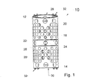
- Fig. 1 shows a preferred embodiment of a total spinal column implant designated 10, which takes its compressed position. Visible are an upper one Outer sleeve 12 and a lower outer sleeve 14, with their facing end faces 16 (see FIG. 2) on a Support ring 18 abut. It can also be seen that the Outer sleeves 12 and 14 are provided with openings 20, through which bone tissue into the interior of the Spine implant 10 can grow.
- the support ring 18 is provided with radially extending openings 22 provided by the clear cross section 24 parts of a Gears 26 can be seen.
- the two show Outer sleeves 12 and 14 directed towards the outside end faces 28 and 30, in turn, with thorn-like projections 32, which protrude axially, are provided. This thorny one Distances 32 penetrate into the contact surfaces of the adjacent Whirl and anchor there the two outer sleeves 12 and 14th
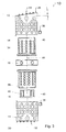
- FIGs. 2 and 3 are an upper inner sleeve 34 and a lower inner sleeve 36 shown in turn in the associated upper outer sleeve 12 and lower outer sleeve 14th are screwed in.
- two grub screws 38 shown in a corresponding threaded bore 40 of the Outer sleeve 12 and 14 can be screwed, causing the Outer sleeve 12 and 14 fixed to the inner sleeve 34 and 36, respectively can be.
- the threaded holes 40 for the grub screws 38 are in the immediate vicinity of the End faces 16 of the outer sleeves 12 and 14.
- a locking element 42 recognizable, with which the two Inner sleeves 34 and 36 are secured together.
- the plane of the front side 28 opposite the orthogonal plane to the longitudinal axis 44 to a Angle ⁇ is inclined. This may cause the spinal implant 10 optimally adapted to the position of the adjacent vertebra, or their position can be corrected. It will each an outer sleeve 12 and 14 selected, the one End face 28 or 30 with the required inclination having. Furthermore, it can be seen that the sleeves 12, 14 34 and 36 and the support ring 18 and the locking element 42 coaxial to each other and with respect to the longitudinal axis 44 are arranged.
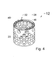
- FIGs. 4 and 5 the two outer sleeves 12 and 14 in enlarged representation, however, wherein the am Inner circumference provided internal thread 46 only schematically is shown or indicated.
- This internal thread 46 is e.g. a fine thread with a pitch of 1 mm and a Diameter of 22 mm and designed as a right-hand thread.
- FIGS. 4 and 5 it can be seen in FIGS. 4 and 5 that a larger, oblong opening 48 in the wall of the Outer sleeves 12 and 14 is provided, through which after the Distraction bone tissue inside the Spinal implant 10 can be filled.
- Fig. 6 shows an enlarged perspective view the inner sleeve 34 and 36, which at its outer periphery with a External thread 50 is provided, which also only is shown schematically or indicated. Also the Inner sleeve 34 and 36 is provided with openings 52. The Inner sleeve 34 and 36 has on one of its end faces 54th a radially outwardly projecting flange 56 which at its outwardly facing end face with the toothing 26, the is designed in particular as a conical tooth is. In the longitudinal section shown in FIG. 7, this is Bevel gear clearly visible.
- the flange 56 is a radially to inside projecting shoulder 58, on which Locking lugs 60 of a locking element 42 can lock.
- Locking element 42 is shown in Fig. 9.
- This Locking element 42 is also sleeve-shaped and has at its the locking lugs 60 opposite side a radially projecting retaining flange 64, behind the corresponding shoulder 58 of the other inner sleeve 36 to lie comes.
- the locking lugs are on resilient tabs 68th provided so that they are deflected radially inward can. In this way, the two inner sleeves 34 and 36 are interconnected.
- Fig. 8 shows the support ring 18 on the two Inner sleeves 34 and 36 sit with their teeth 26.
- the support ring 18 has a radially inward direction projecting shoulder 66, which in total six Segments is divided.
- the shoulder 66 is arranged that it intersects the openings 22, the diameter the openings 22 is greater than the thickness of the shoulder 66th This has the consequence that a part of the toothing 26 in the clear cross-section of the openings 22 protrudes when the Inner sleeves 34 and 36 sit on the shoulder 66.
- On the Gearing 26 can then pass through the opening 22 of externally accessed, as shown in Figs. 1 and 2 is.
- a tool 70th represented, which has an elongated shape and in Cross-section is formed star-shaped.
- the tool 70 also has a toothing 72, which together with the Teeth 26 form a bevel gear.
- the tool can a rigid rod or provided on a flexible shaft so that even difficult-to-reach places easily reachable with the tool 70 and the spinal implant 10 is distractable.
Description
- Fig. 1:
- eine perspektivische Ansicht eines Ausführungsbeispiels des erfindungsgemäßen distrahierbaren Wirbelsäulenimplantats;
- Fig. 2:
- das Wirbelsäulenimplantat gemäß Fig. 1 in distrahierter Stellung;
- Fig. 3:
- das Wirbelsäulenimplantat gemäß Fig. 1 in Expositionsdarstellung;
- Fig. 4:
- eine vergrößerte Wiedergabe einer perspektivischen Darstellung der oberen Außenhülse gemäß Fig. 3;
- Fig. 5:
- eine vergrößerte Wiedergabe einer perspektivischen Darstellung der unteren Außenhülse gemäß Fig. 3;
- Fig. 6:
- eine vergrößerte Wiedergabe einer perspektivischen Darstellung einer Innenhülse;
- Fig. 7:
- einen Längsschnitt durch die Innenhülse;
- Fig. 8:
- eine vergrößerte Wiedergabe einer perspektivischen Darstellung eines Stützringes;
- Fig. 9:
- eine vergrößerte Wiedergabe einer perspektivischen Darstellung eines Rastelements, und
- Fig. 10
- eine perspektivische Darstellung eines Werkzeugs zum Distrahieren des Wirbelsäulenimplantats.
Claims (16)
- Distrahierbares Wirbelsäulenimplantat (10) mit einer ersten Außenhülse (12) und einer koaxial zu dieser angeordneten zweiten Außenhülse (14) und einem inneren Antriebselement, welches mit wenigstens einer der Außenhülsen (12, 14) verschraubt ist, wobei das innere Antriebselement ein erstes Gewinde, z.B. ein Außengewinde (50) und die mit dem Antriebselement verschraubte Außenhülse (12, 14) ein zweites, zum Außengewinde (50) passendes Gewinde, z.B. ein Innengewinde (46) aufweist, dadurch gekennzeichnet, dass das innere Antriebselement auf einem Stützring (18) aufliegt, und das Antriebselement im Bereich seiner dem Stützring (18) zugewandten Stirnseite (54) antreibbar ist.
- Wirbelsäulenimplantat nach einem der vorhergehenden Ansprüche, dadurch gekennzeichnet, dass das Antriebselement zwei Innenhülsen (34 und 36) aufweist.
- Wirbelsäulenimplantat nach Anspruch 2, dadurch gekennzeichnet, dass jeweils eine Innenhülse (34 bzw. 36) in eine Außenhülse (12 und 14) eingeschraubt ist.
- Wirbelsäulenimplantat nach Anspruch 2 oder 3, dadurch gekennzeichnet, dass die Innenhülsen (34 und 36) über den Stützring (18) voneinander beabstandet sind.
- Wirbelsäulenimplantat nach einem der vorhergehenden Ansprüche, dadurch gekennzeichnet, dass die Stirnseite (54) des Antriebselements oder der Innenhülse (34 bzw. 36) mit einer Verzahnung (26) versehen ist.
- Wirbelsäulenimplantat nach einem der vorhergehenden Ansprüche, dadurch gekennzeichnet, dass der Stützring (18) wenigstens eine radiale Öffnung (22) aufweist.
- Wirbelsäulenimplantat nach einem der vorhergehenden Ansprüche, dadurch gekennzeichnet, dass der Stützring (18) eine radial nach innen vorspringende Schulter (66) aufweist, die als Auflage für die Stirnseite (54) der Innenhülse (34, 36) dient.
- Wirbelsäulenimplantat nach Anspruch 6 und 7, dadurch gekennzeichnet, dass die Öffnung (22) und die Schulter (66) sich schneiden.
- Wirbelsäulenimplantat nach Anspruch 8, dadurch gekennzeichnet, dass der Durchmesser der Öffnung (22) größer ist als die Dicke der Schulter (66).
- Wirbelsäulenimplantat nach Anspruch 5 und 6, dadurch gekennzeichnet, dass die Verzahnung (26) in den lichten Querschnitt der Öffnung (22) hineinragt.
- Wirbelsäulenimplantat nach einem der vorhergehenden Ansprüche, dadurch gekennzeichnet, dass die Innenhülsen (34 und 36) und die Außenhülsen (12 und 14) jeweils ein Rechtsgewinde oder jeweils ein Linksgewinde aufweisen.
- Wirbelsäulenimplantat nach einem der vorhergehenden Ansprüche, dadurch gekennzeichnet, dass die Mantelflächen der Innenhülsen (34 und 36) und/oder der Außenhülsen (12 und 14) mit Durchbrüchen (20, 48) versehen sind.
- Wirbelsäulenimplantat nach Anspruch 12, dadurch gekennzeichnet, dass wenigstens einer der Durchbrüche (48) wenigstens einer Hülse (12, 14, 34 oder 36) eine Größe aufweist, so dass die Hülse (12, 14, 34 oder 36) mit Gewebematerial füllbar ist.
- Wirbelsäulenimplantat nach einem der vorhergehenden Ansprüche, dadurch gekennzeichnet, dass eine der Außenhülsen (12 oder 14) eine nach außen weisende Stirnseite (28) aufweist, die unter einem Winkel (α) zur Orthogonalfläche bezüglich der Längsachse (44) steht.
- Wirbelsäulenimplantat nach einem der vorhergehenden Ansprüche, dadurch gekennzeichnet, dass die Außenhülse (12, 14) und die zugeordnete Innenhülse (34, 36) mittels einer radial in die Außenhülse (12, 14) einschraubbaren Madenschraube (38) aneinander fixierbar sind.
- Wirbelsäulenimplantat nach einem der vorhergehenden Ansprüche, dadurch gekennzeichnet, dass die beiden Innenhülsen (34 und 36) durch ein Rastelement (42) am Stützring (18) gehalten werden, wobei das Rastelement (42) nach außen abragende Rastnasen (60) aufweist, die an der Innenhülse (34, 36) vorgesehene, nach innen vorspringende Schultern (58) hintergreifen.
Applications Claiming Priority (3)
| Application Number | Priority Date | Filing Date | Title |
|---|---|---|---|
| DE10210214A DE10210214B4 (de) | 2002-03-02 | 2002-03-02 | Distrahierbares Wirbelsäulenimplantat und Werkzeug zum Distrahieren |
| DE10210214 | 2002-03-02 | ||
| PCT/EP2003/000932 WO2003073964A1 (de) | 2002-03-02 | 2003-01-30 | Distrahierbares wirbelsäulenimplantat und werkzeug zum distrahieren |
Publications (2)
| Publication Number | Publication Date |
|---|---|
| EP1361840A1 EP1361840A1 (de) | 2003-11-19 |
| EP1361840B1 true EP1361840B1 (de) | 2005-09-28 |
Family
ID=27771114
Family Applications (1)
| Application Number | Title | Priority Date | Filing Date |
|---|---|---|---|
| EP03743307A Expired - Lifetime EP1361840B1 (de) | 2002-03-02 | 2003-01-30 | Distrahierbares wirbelsäulenimplantat |
Country Status (6)
| Country | Link |
|---|---|
| US (1) | US7056343B2 (de) |
| EP (1) | EP1361840B1 (de) |
| AT (1) | ATE305280T1 (de) |
| CA (1) | CA2455339C (de) |
| DE (2) | DE10210214B4 (de) |
| WO (1) | WO2003073964A1 (de) |
Cited By (2)
| Publication number | Priority date | Publication date | Assignee | Title |
|---|---|---|---|---|
| DE102006024168A1 (de) * | 2005-12-23 | 2007-11-29 | Biedermann Motech Gmbh | Mehrwandiger Platzhalter |
| US9211193B2 (en) | 2013-08-30 | 2015-12-15 | Aesculap Implant Systems, Llc | Prosthesis, system and method |
Families Citing this family (88)
| Publication number | Priority date | Publication date | Assignee | Title |
|---|---|---|---|---|
| US7918876B2 (en) | 2003-03-24 | 2011-04-05 | Theken Spine, Llc | Spinal implant adjustment device |
| KR100953145B1 (ko) * | 2003-04-11 | 2010-04-16 | 신세스 게엠바하 | 추간판 임플란트용 앵커링 수단 |
| US8568482B2 (en) | 2003-05-14 | 2013-10-29 | Kilian Kraus | Height-adjustable implant to be inserted between vertebral bodies and corresponding handling tool |
| DE20308171U1 (de) * | 2003-05-21 | 2003-07-31 | Aesculap Ag & Co Kg | Wirbelkörperersatzimplantat |
| DE10328307A1 (de) * | 2003-06-23 | 2005-02-03 | Franz Rennebaum | Wirbelkörperprothese |
| US7255714B2 (en) | 2003-09-30 | 2007-08-14 | Michel H. Malek | Vertically adjustable intervertebral disc prosthesis |
| US7819922B2 (en) | 2003-10-16 | 2010-10-26 | Spinal Generations, Llc | Vertebral prosthesis |
| DE102004021861A1 (de) | 2004-05-04 | 2005-11-24 | Biedermann Motech Gmbh | Flexibler Platzhalter |
| US7285134B2 (en) * | 2003-10-22 | 2007-10-23 | Warsaw Orthopedic, Inc. | Vertebral body replacement implant |
| US7862586B2 (en) | 2003-11-25 | 2011-01-04 | Life Spine, Inc. | Spinal stabilization systems |
| DE20320974U1 (de) | 2003-12-11 | 2005-08-25 | Deltacor Gmbh | Längenverstellbares Wirbelsäulen-Implantat |
| US20050200696A1 (en) * | 2004-03-09 | 2005-09-15 | Audiovox Corporation | Display device mountable in a vehicle |
| US7544208B1 (en) * | 2004-05-03 | 2009-06-09 | Theken Spine, Llc | Adjustable corpectomy apparatus |
| US7883543B2 (en) * | 2004-10-01 | 2011-02-08 | Spinal Generations, Llc | Vertebral prosthesis and spinal fixation system |
| US20060136062A1 (en) * | 2004-12-17 | 2006-06-22 | Dinello Alexandre | Height-and angle-adjustable motion disc implant |
| US7722674B1 (en) | 2005-08-12 | 2010-05-25 | Innvotec Surgical Inc. | Linearly expanding spine cage for enhanced spinal fusion |
| US8657882B2 (en) | 2006-04-24 | 2014-02-25 | Warsaw Orthopedic, Inc. | Expandable intervertebral devices and methods of use |
| US20070270960A1 (en) * | 2006-04-24 | 2007-11-22 | Sdgi Holdings, Inc. | Extendable anchor in a vertebral implant and methods of use |
| US7575601B2 (en) * | 2006-04-27 | 2009-08-18 | Warsaw Orthopedic, Inc. | Locking expandable implant and method |
| US7981157B2 (en) * | 2006-04-27 | 2011-07-19 | Warsaw Orthopedic, Inc. | Self-contained expandable implant and method |
| US7914581B2 (en) * | 2006-04-27 | 2011-03-29 | Warsaw Orthopedic, Inc. | Expandable implant, instrument, and method |
| US7758648B2 (en) | 2006-04-27 | 2010-07-20 | Warsaw Orthopedic, Inc. | Stabilized, adjustable expandable implant and method |
| US8187331B2 (en) | 2006-04-27 | 2012-05-29 | Warsaw Orthopedic, Inc. | Expandable vertebral implant and methods of use |
| US7879096B2 (en) | 2006-04-27 | 2011-02-01 | Warsaw Orthopedic, Inc. | Centrally driven expandable implant |
| US7794501B2 (en) | 2006-04-27 | 2010-09-14 | Wasaw Orthopedic, Inc. | Expandable intervertebral spacers and methods of use |
| US7708779B2 (en) | 2006-05-01 | 2010-05-04 | Warsaw Orthopedic, Inc. | Expandable intervertebral spacers and methods of use |
| FR2902315B1 (fr) * | 2006-06-20 | 2008-09-12 | Abbott Spine Sa | Implant intervertebral distractable |
| ES2395298T3 (es) | 2006-07-14 | 2013-02-11 | Biedermann Technologies Gmbh & Co. Kg | Separador para inserción entre dos vértebras |
| US20080027444A1 (en) * | 2006-07-28 | 2008-01-31 | Malek Michel H | Bone anchor device |
| US7815683B2 (en) * | 2006-10-16 | 2010-10-19 | Warsaw Orthopedic, Inc. | Implants with helical supports and methods of use for spacing vertebral members |
| US8920502B1 (en) * | 2006-11-08 | 2014-12-30 | Spinal Usa, Inc. | Vertebral body replacement |
| US9023107B2 (en) * | 2006-11-08 | 2015-05-05 | Spinal Usa, Inc. | Vertebral body replacement |
| WO2008103466A1 (en) | 2007-02-22 | 2008-08-28 | Kyphon Sarl | Expandable devices for emplacement in bone and other body parts and methods of use of such devices |
| JP2010521242A (ja) | 2007-03-13 | 2010-06-24 | ジンテス ゲゼルシャフト ミット ベシュレンクテル ハフツング | 調整可能な椎間インプラント |
| US8142441B2 (en) * | 2008-10-16 | 2012-03-27 | Aesculap Implant Systems, Llc | Surgical instrument and method of use for inserting an implant between two bones |
| US20090112325A1 (en) * | 2007-10-30 | 2009-04-30 | Biospine, Llc | Footplate member and a method for use in a vertebral body replacement device |
| DE102007052042A1 (de) * | 2007-10-30 | 2009-05-14 | Kilian Kraus | Höhenverstellbares Wirbelsäulenimplantat |
| US8182537B2 (en) | 2007-10-30 | 2012-05-22 | Aesculap Implant Systems, Llc | Vertebral body replacement device and method for use to maintain a space between two vertebral bodies within a spine |
| US8591587B2 (en) | 2007-10-30 | 2013-11-26 | Aesculap Implant Systems, Llc | Vertebral body replacement device and method for use to maintain a space between two vertebral bodies within a spine |
| US8241294B2 (en) | 2007-12-19 | 2012-08-14 | Depuy Spine, Inc. | Instruments for expandable corpectomy spinal fusion cage |
| US8241363B2 (en) | 2007-12-19 | 2012-08-14 | Depuy Spine, Inc. | Expandable corpectomy spinal fusion cage |
| US8617214B2 (en) | 2008-01-07 | 2013-12-31 | Mmsn Limited Partnership | Spinal tension band |
| US7935133B2 (en) | 2008-02-08 | 2011-05-03 | Mmsn Limited Partnership | Interlaminar hook |
| EP2271289A4 (de) * | 2008-03-28 | 2013-01-09 | K2M Inc | Expandierbarer käfig mit verschlussvorrichtung |
| EP2268219B1 (de) | 2008-03-28 | 2016-11-09 | K2M, Inc. | Expandierbarer käfig |
| US8187304B2 (en) * | 2008-11-10 | 2012-05-29 | Malek Michel H | Facet fusion system |
| US9492214B2 (en) * | 2008-12-18 | 2016-11-15 | Michel H. Malek | Flexible spinal stabilization system |
| US8252054B2 (en) * | 2009-01-14 | 2012-08-28 | Stout Medical Group, L.P. | Expandable support device and method of use |
| US8142435B2 (en) | 2009-02-19 | 2012-03-27 | Aesculap Implant Systems, Llc | Multi-functional surgical instrument and method of use for inserting an implant between two bones |
| US9687357B2 (en) | 2009-03-12 | 2017-06-27 | Nuvasive, Inc. | Vertebral body replacement |
| US9387090B2 (en) | 2009-03-12 | 2016-07-12 | Nuvasive, Inc. | Vertebral body replacement |
| WO2013025448A1 (en) * | 2011-08-09 | 2013-02-21 | Nuvasive, Inc. | Vertebral body replacement |
| WO2010120782A2 (en) * | 2009-04-13 | 2010-10-21 | Biospine, Llc | Variable height intervertebral devices and methods for use |
| US8123809B2 (en) * | 2009-04-16 | 2012-02-28 | Warsaw Orthopedic, Inc. | Deployment system and method for an expandable vertebral implant |
| US8292963B2 (en) | 2009-04-23 | 2012-10-23 | Warsaw Orthopedic, Inc. | Expandable implant for supporting skeletal structures |
| US8876905B2 (en) | 2009-04-29 | 2014-11-04 | DePuy Synthes Products, LLC | Minimally invasive corpectomy cage and instrument |
| US8211178B2 (en) | 2009-06-18 | 2012-07-03 | Warsaw Orthopedic | Intervertebral implant with a pivoting end cap |
| WO2011060071A1 (en) | 2009-11-10 | 2011-05-19 | Medivest, Llc | Tissue spacer implant, implant tool, and methods of use thereof |
| GB2493810B (en) | 2009-11-11 | 2013-07-03 | Nuvasive Inc | Surgical access system |
| US8268002B2 (en) * | 2010-01-27 | 2012-09-18 | Warsaw Orthopedic, Inc. | Slide-on end cap for a vertebral implant |
| US8282683B2 (en) | 2010-04-12 | 2012-10-09 | Globus Medical, Inc. | Expandable vertebral implant |
| US8870880B2 (en) | 2010-04-12 | 2014-10-28 | Globus Medical, Inc. | Angling inserter tool for expandable vertebral implant |
| US8591585B2 (en) | 2010-04-12 | 2013-11-26 | Globus Medical, Inc. | Expandable vertebral implant |
| US11426287B2 (en) | 2010-04-12 | 2022-08-30 | Globus Medical Inc. | Expandable vertebral implant |
| US9579211B2 (en) * | 2010-04-12 | 2017-02-28 | Globus Medical, Inc. | Expandable vertebral implant |
| US9301850B2 (en) | 2010-04-12 | 2016-04-05 | Globus Medical, Inc. | Expandable vertebral implant |
| GB201006173D0 (en) | 2010-04-14 | 2010-06-02 | Depuy Ireland | A distractor |
| US9301787B2 (en) | 2010-09-27 | 2016-04-05 | Mmsn Limited Partnership | Medical apparatus and method for spinal surgery |
| US20120116457A1 (en) * | 2010-11-06 | 2012-05-10 | Limited Liability Company; | Stabilizer for assisting stabilization of a spinal implant and method of using the stabilizer |
| US9084684B2 (en) * | 2010-11-06 | 2015-07-21 | Igip, Llc | Stabilizer for assisting stabilization of a spinal implant |
| US8377140B2 (en) | 2011-01-12 | 2013-02-19 | Ebi, Llc | Expandable spinal implant device |
| US8740980B2 (en) | 2011-01-27 | 2014-06-03 | Warsaw Orthopedic, Inc. | Expandable medical implant |
| DE102011002076A1 (de) * | 2011-04-15 | 2012-10-18 | Z.-Medical Gmbh & Co. Kg | Zwischenwirbelimplantat und Vorrichtung zum Einbringen |
| GB201115411D0 (en) | 2011-09-07 | 2011-10-19 | Depuy Ireland | Surgical instrument |
| US9707096B2 (en) | 2013-03-14 | 2017-07-18 | K2M, Inc. | Spinal fixation device |
| US10292832B2 (en) | 2013-03-14 | 2019-05-21 | Ohio State Innovation Foundation | Spinal fixation device |
| US9968460B2 (en) | 2013-03-15 | 2018-05-15 | Medsmart Innovation Inc. | Dynamic spinal segment replacement |
| US9566167B2 (en) | 2013-08-22 | 2017-02-14 | K2M, Inc. | Expandable spinal implant |
| US11452612B2 (en) * | 2014-10-09 | 2022-09-27 | Warsaw Orthopedic, Inc. | Spinal implant system and method |
| US9974663B2 (en) | 2014-10-09 | 2018-05-22 | Warsaw Orthopedic, Inc. | Spinal implant system and method |
| US10363142B2 (en) | 2014-12-11 | 2019-07-30 | K2M, Inc. | Expandable spinal implants |
| US9775719B2 (en) | 2015-03-23 | 2017-10-03 | Musc Foundation For Research Development | Expandable vertebral body replacement device and method |
| US10327908B2 (en) | 2015-09-18 | 2019-06-25 | K2M, Inc. | Corpectomy device and methods of use thereof |
| WO2018097857A1 (en) * | 2016-11-28 | 2018-05-31 | Musc Foundation For Research Development | Expandable vertebral body replacement device and method |
| CN107041800A (zh) * | 2017-01-21 | 2017-08-15 | 张洪剑 | 新型分体式人工椎骨装置 |
| US10441430B2 (en) | 2017-07-24 | 2019-10-15 | K2M, Inc. | Expandable spinal implants |
| US11678894B2 (en) | 2017-12-15 | 2023-06-20 | Jonathan P. Cabot | Knee balancing instrument |
| US11135070B2 (en) * | 2018-02-14 | 2021-10-05 | Titan Spine, Inc. | Modular adjustable corpectomy cage |
Family Cites Families (22)
| Publication number | Priority date | Publication date | Assignee | Title |
|---|---|---|---|---|
| US4553273A (en) * | 1983-11-23 | 1985-11-19 | Henry Ford Hospital | Vertebral body prosthesis and spine stabilizing method |
| FR2575059B1 (fr) * | 1984-12-21 | 1988-11-10 | Daher Youssef | Dispositif d'etaiement utilisable dans une prothese vertebrale |
| US5236460A (en) * | 1990-02-12 | 1993-08-17 | Midas Rex Pneumatic Tools, Inc. | Vertebral body prosthesis |
| ES2041221B1 (es) * | 1992-04-24 | 1994-05-16 | Alacreu Jose Vicente Barbera | Procedimiento para la substitucion vertebral protesica en la cirugia de los tumores malignos y protesis para la practica de dicho procedimiento. |
| DE4423257C2 (de) * | 1994-07-02 | 2001-07-12 | Ulrich Heinrich | Implantat zum Einsetzen zwischen Wirbelkörper der Wirbelsäule als Platzhalter |
| TW316844B (de) * | 1994-12-09 | 1997-10-01 | Sofamor Danek Group Inc | |
| DE19519101B4 (de) * | 1995-05-24 | 2009-04-23 | Harms, Jürgen, Prof. Dr. | Höhenverstellbarer Wirbelkörperersatz |
| DE19622827B4 (de) * | 1996-06-07 | 2009-04-23 | Ulrich, Heinrich | Implantat zum Einsetzen zwischen Wirbelkörper als Platzhalter |
| US5702455A (en) * | 1996-07-03 | 1997-12-30 | Saggar; Rahul | Expandable prosthesis for spinal fusion |
| US6190414B1 (en) * | 1996-10-31 | 2001-02-20 | Surgical Dynamics Inc. | Apparatus for fusion of adjacent bone structures |
| US5916267A (en) * | 1997-04-07 | 1999-06-29 | Arthit Sitiso | Anterior spinal implant system for vertebral body prosthesis |
| ES2182055T3 (es) * | 1997-04-15 | 2003-03-01 | Synthes Ag | Protesis de vertebra telescopica. |
| BE1011217A3 (nl) * | 1997-06-16 | 1999-06-01 | Vanderschot Paul | Intercorporeel implantaat voor een operatieve of endoscopische anterieure fusie na corporectomie ter hoogte van de thoraco-lumbale wervelzuil. |
| ATE247442T1 (de) * | 1997-09-30 | 2003-09-15 | Ct Pulse Orthopedics Ltd | Rohrförmiger stützkörper zum überbrücken zweier wirbel |
| DE19816782A1 (de) * | 1998-04-16 | 1999-10-28 | Ulrich Gmbh & Co Kg | Implantat zum Einsetzen zwischen Wirbelkörper der Wirbelsäule |
| ES2222608T3 (es) * | 1998-10-15 | 2005-02-01 | Synthes Ag Chur | Protesis vertebral telescopica. |
| WO2002009626A1 (en) * | 1999-07-26 | 2002-02-07 | Advanced Prosthetic Technologies, Inc. | Improved spinal surgical prosthesis |
| US6866682B1 (en) * | 1999-09-02 | 2005-03-15 | Stryker Spine | Distractable corpectomy device |
| AR027685A1 (es) * | 2000-03-22 | 2003-04-09 | Synthes Ag | Forma de tejido y metodo para realizarlo |
| DE50109876D1 (de) | 2000-03-31 | 2006-06-29 | Koenigsee Implantate & Instr | Höhenvariierbares wirbelkörperimplantat und betätigungsinstrumentenset dafür |
| DE10065232C2 (de) * | 2000-12-27 | 2002-11-14 | Ulrich Gmbh & Co Kg | Implantat zum Einsetzen zwischen Wirbelkörper sowie Operationsinstrument zur Handhabung des Implantats |
| DE10138079B4 (de) * | 2001-08-03 | 2004-02-12 | Biedermann Motech Gmbh | Platzhalter mit veränderbarer axialer Länge |
-
2002
- 2002-03-02 DE DE10210214A patent/DE10210214B4/de not_active Expired - Lifetime
-
2003
- 2003-01-30 CA CA002455339A patent/CA2455339C/en not_active Expired - Fee Related
- 2003-01-30 WO PCT/EP2003/000932 patent/WO2003073964A1/de active IP Right Grant
- 2003-01-30 DE DE50301242T patent/DE50301242D1/de not_active Expired - Lifetime
- 2003-01-30 EP EP03743307A patent/EP1361840B1/de not_active Expired - Lifetime
- 2003-01-30 US US10/476,811 patent/US7056343B2/en not_active Expired - Lifetime
- 2003-01-30 AT AT03743307T patent/ATE305280T1/de active
Cited By (7)
| Publication number | Priority date | Publication date | Assignee | Title |
|---|---|---|---|---|
| DE102006024168A1 (de) * | 2005-12-23 | 2007-11-29 | Biedermann Motech Gmbh | Mehrwandiger Platzhalter |
| US9254199B2 (en) | 2005-12-23 | 2016-02-09 | Biedermann Technologies GmbH & Co., KG | Multi-walled placeholder |
| US9814595B2 (en) | 2005-12-23 | 2017-11-14 | Biedermann Technologies Gmbh & Co. Kg. | Multi-walled placeholder |
| US10130485B2 (en) | 2005-12-23 | 2018-11-20 | Biedermann Technologies Gmbh & Co. Kg | Multi-walled placeholder |
| US11083589B2 (en) | 2005-12-23 | 2021-08-10 | Biedermann Technologies Gmbh & Co. Kg | Multi-walled placeholder |
| US11883299B2 (en) | 2005-12-23 | 2024-01-30 | Biedermann Technologies Gmbh & Co. Kg | Multi-walled placeholder |
| US9211193B2 (en) | 2013-08-30 | 2015-12-15 | Aesculap Implant Systems, Llc | Prosthesis, system and method |
Also Published As
| Publication number | Publication date |
|---|---|
| WO2003073964A1 (de) | 2003-09-12 |
| DE10210214B4 (de) | 2005-01-05 |
| ATE305280T1 (de) | 2005-10-15 |
| CA2455339A1 (en) | 2003-09-12 |
| US7056343B2 (en) | 2006-06-06 |
| DE50301242D1 (de) | 2006-02-09 |
| CA2455339C (en) | 2009-01-13 |
| EP1361840A1 (de) | 2003-11-19 |
| US20040172129A1 (en) | 2004-09-02 |
| DE10210214A1 (de) | 2003-09-25 |
Similar Documents
| Publication | Publication Date | Title |
|---|---|---|
| EP1361840B1 (de) | Distrahierbares wirbelsäulenimplantat | |
| EP2777629B1 (de) | Aufspreizbares Implantat für die Wirbelsäule | |
| EP0923355B1 (de) | Implantat zum fusionieren von zwei benachbarten wirbeln der wirbelsäule | |
| EP0622056B1 (de) | Implantierbares Verankerungsorgan zur Aufnahme von Prothesen u.dgl. | |
| DE4423257C2 (de) | Implantat zum Einsetzen zwischen Wirbelkörper der Wirbelsäule als Platzhalter | |
| DE19509317B4 (de) | Implantat zum Einsetzen zwischen Wirbelkörper der Wirbelsäule als Platzhalter | |
| DE69813807T2 (de) | Implantat als platzhalter zwischen wirbelkörpern | |
| EP0491138B1 (de) | Vorrichtung zur Fixation von Knochenbrüchen | |
| EP1663036B1 (de) | Vorrichtung zur behandlung von frakturen des femur | |
| DE10357926B3 (de) | Längenverstellbares Wirbelsäulen-Implantat | |
| DE3936702C2 (de) | Pedikelschraube und Korrektur- und Haltevorrichtung mit einer solchen Pedikelschraube | |
| EP1620044B1 (de) | Zwischenwirbelimplantat | |
| EP1608278B1 (de) | Aufnahme für ein verblockungselement und verblockungselement | |
| DE4302397C2 (de) | Künstlicher Wirbelabstandshalter | |
| DE10065232C2 (de) | Implantat zum Einsetzen zwischen Wirbelkörper sowie Operationsinstrument zur Handhabung des Implantats | |
| WO1994026194A1 (de) | Knochenchirurgische haltevorrichtung | |
| EP1501453A1 (de) | Höhenverstellbares implantat zum einsetzen zwischen wirbelkörpern und handhabungswerkzeug | |
| EP1246578A2 (de) | Knochenschraube | |
| CH687230A5 (de) | Schaftkomponente fuer eine Endogelenkprothese. | |
| DE19816832C1 (de) | Wirbelkörperfusionsimplantat | |
| DE10127924C1 (de) | Wirbelersatzkörper | |
| DE1930354B2 (de) | Fixationsvorrichtung | |
| EP1935360A1 (de) | Plattenimplantat, insbesondere für die Anwendung an einer Wirbelsäule, mit einem Schraubenverschlusssystem | |
| DE102018101843A1 (de) | Schraube zur Wirbel- oder Knochenstabilisierung | |
| DE3828013A1 (de) | Dentalimplantat zum einsetzen in kieferknochen |
Legal Events
| Date | Code | Title | Description |
|---|---|---|---|
| PUAI | Public reference made under article 153(3) epc to a published international application that has entered the european phase |
Free format text: ORIGINAL CODE: 0009012 |
|
| 17P | Request for examination filed |
Effective date: 20030919 |
|
| AK | Designated contracting states |
Kind code of ref document: A1 Designated state(s): AT BE BG CH CY CZ DE DK EE ES FI FR GB GR HU IE IT LI LU MC NL PT SE SI SK TR |
|
| RAP1 | Party data changed (applicant data changed or rights of an application transferred) |
Owner name: SCHAEFER, BERND |
|
| RIN1 | Information on inventor provided before grant (corrected) |
Inventor name: TRAUTWEIN, THILO Inventor name: SCHAEFER, BERND |
|
| 17Q | First examination report despatched |
Effective date: 20040414 |
|
| RIN1 | Information on inventor provided before grant (corrected) |
Inventor name: LILJENQVIST, ULF Inventor name: TRAUTWEIN, THILO Inventor name: SCHAEFER, BERND |
|
| RAP1 | Party data changed (applicant data changed or rights of an application transferred) |
Owner name: DEPUY SPINE SAERL |
|
| GRAP | Despatch of communication of intention to grant a patent |
Free format text: ORIGINAL CODE: EPIDOSNIGR1 |
|
| GRAS | Grant fee paid |
Free format text: ORIGINAL CODE: EPIDOSNIGR3 |
|
| GRAA | (expected) grant |
Free format text: ORIGINAL CODE: 0009210 |
|
| AK | Designated contracting states |
Kind code of ref document: B1 Designated state(s): AT BE BG CH CY CZ DE DK EE ES FI FR GB GR HU IE IT LI LU MC NL PT SE SI SK TR |
|
| PG25 | Lapsed in a contracting state [announced via postgrant information from national office to epo] |
Ref country code: IT Free format text: LAPSE BECAUSE OF FAILURE TO SUBMIT A TRANSLATION OF THE DESCRIPTION OR TO PAY THE FEE WITHIN THE PRESCRIBED TIME-LIMIT;WARNING: LAPSES OF ITALIAN PATENTS WITH EFFECTIVE DATE BEFORE 2007 MAY HAVE OCCURRED AT ANY TIME BEFORE 2007. THE CORRECT EFFECTIVE DATE MAY BE DIFFERENT FROM THE ONE RECORDED. Effective date: 20050928 Ref country code: SI Free format text: LAPSE BECAUSE OF FAILURE TO SUBMIT A TRANSLATION OF THE DESCRIPTION OR TO PAY THE FEE WITHIN THE PRESCRIBED TIME-LIMIT Effective date: 20050928 Ref country code: IE Free format text: LAPSE BECAUSE OF FAILURE TO SUBMIT A TRANSLATION OF THE DESCRIPTION OR TO PAY THE FEE WITHIN THE PRESCRIBED TIME-LIMIT Effective date: 20050928 Ref country code: SK Free format text: LAPSE BECAUSE OF FAILURE TO SUBMIT A TRANSLATION OF THE DESCRIPTION OR TO PAY THE FEE WITHIN THE PRESCRIBED TIME-LIMIT Effective date: 20050928 Ref country code: NL Free format text: LAPSE BECAUSE OF FAILURE TO SUBMIT A TRANSLATION OF THE DESCRIPTION OR TO PAY THE FEE WITHIN THE PRESCRIBED TIME-LIMIT Effective date: 20050928 Ref country code: FI Free format text: LAPSE BECAUSE OF FAILURE TO SUBMIT A TRANSLATION OF THE DESCRIPTION OR TO PAY THE FEE WITHIN THE PRESCRIBED TIME-LIMIT Effective date: 20050928 |
|
| REG | Reference to a national code |
Ref country code: GB Ref legal event code: FG4D Free format text: NOT ENGLISH |
|
| RTI1 | Title (correction) |
Free format text: DISTRACTIBLE VERTEBRAL COLUMN IMPLANT |
|
| REG | Reference to a national code |
Ref country code: CH Ref legal event code: NV Representative=s name: TROESCH SCHEIDEGGER WERNER AG Ref country code: CH Ref legal event code: EP |
|
| GBT | Gb: translation of ep patent filed (gb section 77(6)(a)/1977) |
Effective date: 20050928 |
|
| REG | Reference to a national code |
Ref country code: IE Ref legal event code: FG4D Free format text: LANGUAGE OF EP DOCUMENT: GERMAN |
|
| PG25 | Lapsed in a contracting state [announced via postgrant information from national office to epo] |
Ref country code: SE Free format text: LAPSE BECAUSE OF FAILURE TO SUBMIT A TRANSLATION OF THE DESCRIPTION OR TO PAY THE FEE WITHIN THE PRESCRIBED TIME-LIMIT Effective date: 20051228 Ref country code: GR Free format text: LAPSE BECAUSE OF FAILURE TO SUBMIT A TRANSLATION OF THE DESCRIPTION OR TO PAY THE FEE WITHIN THE PRESCRIBED TIME-LIMIT Effective date: 20051228 Ref country code: DK Free format text: LAPSE BECAUSE OF FAILURE TO SUBMIT A TRANSLATION OF THE DESCRIPTION OR TO PAY THE FEE WITHIN THE PRESCRIBED TIME-LIMIT Effective date: 20051228 Ref country code: BG Free format text: LAPSE BECAUSE OF FAILURE TO SUBMIT A TRANSLATION OF THE DESCRIPTION OR TO PAY THE FEE WITHIN THE PRESCRIBED TIME-LIMIT Effective date: 20051228 |
|
| PG25 | Lapsed in a contracting state [announced via postgrant information from national office to epo] |
Ref country code: ES Free format text: LAPSE BECAUSE OF FAILURE TO SUBMIT A TRANSLATION OF THE DESCRIPTION OR TO PAY THE FEE WITHIN THE PRESCRIBED TIME-LIMIT Effective date: 20060108 |
|
| PG25 | Lapsed in a contracting state [announced via postgrant information from national office to epo] |
Ref country code: BE Free format text: LAPSE BECAUSE OF NON-PAYMENT OF DUE FEES Effective date: 20060131 Ref country code: MC Free format text: LAPSE BECAUSE OF NON-PAYMENT OF DUE FEES Effective date: 20060131 Ref country code: LU Free format text: LAPSE BECAUSE OF NON-PAYMENT OF DUE FEES Effective date: 20060131 |
|
| REF | Corresponds to: |
Ref document number: 50301242 Country of ref document: DE Date of ref document: 20060209 Kind code of ref document: P |
|
| PG25 | Lapsed in a contracting state [announced via postgrant information from national office to epo] |
Ref country code: PT Free format text: LAPSE BECAUSE OF FAILURE TO SUBMIT A TRANSLATION OF THE DESCRIPTION OR TO PAY THE FEE WITHIN THE PRESCRIBED TIME-LIMIT Effective date: 20060228 |
|
| NLV1 | Nl: lapsed or annulled due to failure to fulfill the requirements of art. 29p and 29m of the patents act | ||
| PG25 | Lapsed in a contracting state [announced via postgrant information from national office to epo] |
Ref country code: HU Free format text: LAPSE BECAUSE OF FAILURE TO SUBMIT A TRANSLATION OF THE DESCRIPTION OR TO PAY THE FEE WITHIN THE PRESCRIBED TIME-LIMIT Effective date: 20060329 |
|
| REG | Reference to a national code |
Ref country code: IE Ref legal event code: FD4D |
|
| PLBE | No opposition filed within time limit |
Free format text: ORIGINAL CODE: 0009261 |
|
| STAA | Information on the status of an ep patent application or granted ep patent |
Free format text: STATUS: NO OPPOSITION FILED WITHIN TIME LIMIT |
|
| 26N | No opposition filed |
Effective date: 20060629 |
|
| EN | Fr: translation not filed | ||
| PG25 | Lapsed in a contracting state [announced via postgrant information from national office to epo] |
Ref country code: FR Free format text: LAPSE BECAUSE OF FAILURE TO SUBMIT A TRANSLATION OF THE DESCRIPTION OR TO PAY THE FEE WITHIN THE PRESCRIBED TIME-LIMIT Effective date: 20061124 |
|
| BERE | Be: lapsed |
Owner name: DEPUY SPINE SARL Effective date: 20060131 |
|
| PG25 | Lapsed in a contracting state [announced via postgrant information from national office to epo] |
Ref country code: EE Free format text: LAPSE BECAUSE OF FAILURE TO SUBMIT A TRANSLATION OF THE DESCRIPTION OR TO PAY THE FEE WITHIN THE PRESCRIBED TIME-LIMIT Effective date: 20050928 |
|
| PG25 | Lapsed in a contracting state [announced via postgrant information from national office to epo] |
Ref country code: TR Free format text: LAPSE BECAUSE OF FAILURE TO SUBMIT A TRANSLATION OF THE DESCRIPTION OR TO PAY THE FEE WITHIN THE PRESCRIBED TIME-LIMIT Effective date: 20050928 |
|
| PG25 | Lapsed in a contracting state [announced via postgrant information from national office to epo] |
Ref country code: FR Free format text: LAPSE BECAUSE OF FAILURE TO SUBMIT A TRANSLATION OF THE DESCRIPTION OR TO PAY THE FEE WITHIN THE PRESCRIBED TIME-LIMIT Effective date: 20060131 |
|
| PG25 | Lapsed in a contracting state [announced via postgrant information from national office to epo] |
Ref country code: FR Free format text: LAPSE BECAUSE OF FAILURE TO SUBMIT A TRANSLATION OF THE DESCRIPTION OR TO PAY THE FEE WITHIN THE PRESCRIBED TIME-LIMIT Effective date: 20050928 Ref country code: CY Free format text: LAPSE BECAUSE OF FAILURE TO SUBMIT A TRANSLATION OF THE DESCRIPTION OR TO PAY THE FEE WITHIN THE PRESCRIBED TIME-LIMIT Effective date: 20050928 |
|
| PGFP | Annual fee paid to national office [announced via postgrant information from national office to epo] |
Ref country code: CZ Payment date: 20140114 Year of fee payment: 12 |
|
| PGFP | Annual fee paid to national office [announced via postgrant information from national office to epo] |
Ref country code: AT Payment date: 20131224 Year of fee payment: 12 |
|
| REG | Reference to a national code |
Ref country code: AT Ref legal event code: MM01 Ref document number: 305280 Country of ref document: AT Kind code of ref document: T Effective date: 20150130 |
|
| PG25 | Lapsed in a contracting state [announced via postgrant information from national office to epo] |
Ref country code: CZ Free format text: LAPSE BECAUSE OF NON-PAYMENT OF DUE FEES Effective date: 20150130 |
|
| PG25 | Lapsed in a contracting state [announced via postgrant information from national office to epo] |
Ref country code: AT Free format text: LAPSE BECAUSE OF NON-PAYMENT OF DUE FEES Effective date: 20150130 |
|
| PGFP | Annual fee paid to national office [announced via postgrant information from national office to epo] |
Ref country code: GB Payment date: 20211209 Year of fee payment: 20 |
|
| PGFP | Annual fee paid to national office [announced via postgrant information from national office to epo] |
Ref country code: CH Payment date: 20211216 Year of fee payment: 20 |
|
| PGFP | Annual fee paid to national office [announced via postgrant information from national office to epo] |
Ref country code: DE Payment date: 20211207 Year of fee payment: 20 |
|
| REG | Reference to a national code |
Ref country code: DE Ref legal event code: R071 Ref document number: 50301242 Country of ref document: DE |
|
| REG | Reference to a national code |
Ref country code: CH Ref legal event code: PL |
|
| REG | Reference to a national code |
Ref country code: GB Ref legal event code: PE20 Expiry date: 20230129 |
|
| PG25 | Lapsed in a contracting state [announced via postgrant information from national office to epo] |
Ref country code: GB Free format text: LAPSE BECAUSE OF EXPIRATION OF PROTECTION Effective date: 20230129 |