EP1361113B1 - Leuchte für ein Fahrzeug, insbesondere Leseleuchte für ein Flugzeug - Google Patents
Leuchte für ein Fahrzeug, insbesondere Leseleuchte für ein Flugzeug Download PDFInfo
- Publication number
- EP1361113B1 EP1361113B1 EP02010557A EP02010557A EP1361113B1 EP 1361113 B1 EP1361113 B1 EP 1361113B1 EP 02010557 A EP02010557 A EP 02010557A EP 02010557 A EP02010557 A EP 02010557A EP 1361113 B1 EP1361113 B1 EP 1361113B1
- Authority
- EP
- European Patent Office
- Prior art keywords
- housing
- lamp
- pull
- vehicle according
- plug element
- Prior art date
- Legal status (The legal status is an assumption and is not a legal conclusion. Google has not performed a legal analysis and makes no representation as to the accuracy of the status listed.)
- Expired - Lifetime
Links
- 238000001816 cooling Methods 0.000 claims description 11
- 238000009434 installation Methods 0.000 description 4
- 238000010276 construction Methods 0.000 description 3
- 101100390736 Danio rerio fign gene Proteins 0.000 description 2
- 101100390738 Mus musculus Fign gene Proteins 0.000 description 2
- 229920002430 Fibre-reinforced plastic Polymers 0.000 description 1
- 238000005253 cladding Methods 0.000 description 1
- 238000001514 detection method Methods 0.000 description 1
- 239000011151 fibre-reinforced plastic Substances 0.000 description 1
- -1 if necessary Substances 0.000 description 1
- 238000005286 illumination Methods 0.000 description 1
- 239000000463 material Substances 0.000 description 1
Images


Classifications
-
- F—MECHANICAL ENGINEERING; LIGHTING; HEATING; WEAPONS; BLASTING
- F21—LIGHTING
- F21V—FUNCTIONAL FEATURES OR DETAILS OF LIGHTING DEVICES OR SYSTEMS THEREOF; STRUCTURAL COMBINATIONS OF LIGHTING DEVICES WITH OTHER ARTICLES, NOT OTHERWISE PROVIDED FOR
- F21V29/00—Protecting lighting devices from thermal damage; Cooling or heating arrangements specially adapted for lighting devices or systems
- F21V29/50—Cooling arrangements
- F21V29/70—Cooling arrangements characterised by passive heat-dissipating elements, e.g. heat-sinks
- F21V29/74—Cooling arrangements characterised by passive heat-dissipating elements, e.g. heat-sinks with fins or blades
- F21V29/77—Cooling arrangements characterised by passive heat-dissipating elements, e.g. heat-sinks with fins or blades with essentially identical diverging planar fins or blades, e.g. with fan-like or star-like cross-section
- F21V29/773—Cooling arrangements characterised by passive heat-dissipating elements, e.g. heat-sinks with fins or blades with essentially identical diverging planar fins or blades, e.g. with fan-like or star-like cross-section the planes containing the fins or blades having the direction of the light emitting axis
-
- B—PERFORMING OPERATIONS; TRANSPORTING
- B60—VEHICLES IN GENERAL
- B60Q—ARRANGEMENT OF SIGNALLING OR LIGHTING DEVICES, THE MOUNTING OR SUPPORTING THEREOF OR CIRCUITS THEREFOR, FOR VEHICLES IN GENERAL
- B60Q3/00—Arrangement of lighting devices for vehicle interiors; Lighting devices specially adapted for vehicle interiors
- B60Q3/40—Arrangement of lighting devices for vehicle interiors; Lighting devices specially adapted for vehicle interiors specially adapted for specific vehicle types
- B60Q3/41—Arrangement of lighting devices for vehicle interiors; Lighting devices specially adapted for vehicle interiors specially adapted for specific vehicle types for mass transit vehicles, e.g. buses
- B60Q3/44—Spotlighting, e.g. reading lamps
-
- F—MECHANICAL ENGINEERING; LIGHTING; HEATING; WEAPONS; BLASTING
- F21—LIGHTING
- F21S—NON-PORTABLE LIGHTING DEVICES; SYSTEMS THEREOF; VEHICLE LIGHTING DEVICES SPECIALLY ADAPTED FOR VEHICLE EXTERIORS
- F21S45/00—Arrangements within vehicle lighting devices specially adapted for vehicle exteriors, for purposes other than emission or distribution of light
- F21S45/40—Cooling of lighting devices
- F21S45/47—Passive cooling, e.g. using fins, thermal conductive elements or openings
- F21S45/48—Passive cooling, e.g. using fins, thermal conductive elements or openings with means for conducting heat from the inside to the outside of the lighting devices, e.g. with fins on the outer surface of the lighting device
-
- F—MECHANICAL ENGINEERING; LIGHTING; HEATING; WEAPONS; BLASTING
- F21—LIGHTING
- F21V—FUNCTIONAL FEATURES OR DETAILS OF LIGHTING DEVICES OR SYSTEMS THEREOF; STRUCTURAL COMBINATIONS OF LIGHTING DEVICES WITH OTHER ARTICLES, NOT OTHERWISE PROVIDED FOR
- F21V19/00—Fastening of light sources or lamp holders
- F21V19/04—Fastening of light sources or lamp holders with provision for changing light source, e.g. turret
-
- F—MECHANICAL ENGINEERING; LIGHTING; HEATING; WEAPONS; BLASTING
- F21—LIGHTING
- F21V—FUNCTIONAL FEATURES OR DETAILS OF LIGHTING DEVICES OR SYSTEMS THEREOF; STRUCTURAL COMBINATIONS OF LIGHTING DEVICES WITH OTHER ARTICLES, NOT OTHERWISE PROVIDED FOR
- F21V27/00—Cable-stowing arrangements structurally associated with lighting devices, e.g. reels
-
- B—PERFORMING OPERATIONS; TRANSPORTING
- B64—AIRCRAFT; AVIATION; COSMONAUTICS
- B64D—EQUIPMENT FOR FITTING IN OR TO AIRCRAFT; FLIGHT SUITS; PARACHUTES; ARRANGEMENT OR MOUNTING OF POWER PLANTS OR PROPULSION TRANSMISSIONS IN AIRCRAFT
- B64D11/00—Passenger or crew accommodation; Flight-deck installations not otherwise provided for
- B64D2011/0053—Cabin passenger reading lights
-
- F—MECHANICAL ENGINEERING; LIGHTING; HEATING; WEAPONS; BLASTING
- F21—LIGHTING
- F21W—INDEXING SCHEME ASSOCIATED WITH SUBCLASSES F21K, F21L, F21S and F21V, RELATING TO USES OR APPLICATIONS OF LIGHTING DEVICES OR SYSTEMS
- F21W2106/00—Interior vehicle lighting devices
-
- F—MECHANICAL ENGINEERING; LIGHTING; HEATING; WEAPONS; BLASTING
- F21—LIGHTING
- F21W—INDEXING SCHEME ASSOCIATED WITH SUBCLASSES F21K, F21L, F21S and F21V, RELATING TO USES OR APPLICATIONS OF LIGHTING DEVICES OR SYSTEMS
- F21W2107/00—Use or application of lighting devices on or in particular types of vehicles
- F21W2107/30—Use or application of lighting devices on or in particular types of vehicles for aircraft
-
- F—MECHANICAL ENGINEERING; LIGHTING; HEATING; WEAPONS; BLASTING
- F21—LIGHTING
- F21Y—INDEXING SCHEME ASSOCIATED WITH SUBCLASSES F21K, F21L, F21S and F21V, RELATING TO THE FORM OR THE KIND OF THE LIGHT SOURCES OR OF THE COLOUR OF THE LIGHT EMITTED
- F21Y2115/00—Light-generating elements of semiconductor light sources
- F21Y2115/10—Light-emitting diodes [LED]
Definitions
- the invention relates to a lamp for a vehicle and in particular a lamp for the interior of a vehicle, which is in particular the reading light for an aircraft.
- Vehicle lights generally have a housing in which a light source, such as a light bulb or one or more LEDS are arranged.
- a plug element is provided, on which there is usually an electrical cable.
- a pull-out plug element is known from BE 1011148-A.
- An object of the invention is therefore to provide a light for a vehicle and in particular a reading light for an aircraft, which has a convenient manageable, yet space-saving connector element.
- the luminaire according to the invention has a pull-off aid element with which the plug element can be pulled off the housing in a withdrawal direction.
- the withdrawal aid element is arranged transversely to the withdrawal direction pivotally mounted on the plug element.
- the trigger member for manual detection and manual pulling is formed, which is realized for example in the form of a widening of the second end or in the form of an opening into which one can grasp with one or more fingers of a hand.
- the withdrawal aid element is pivotable between a parking position and a withdrawal position. In the park position, the trigger pull element bears against the housing, while it protrudes from the housing in the trigger position.
- the trigger element Due to the pivotable mounting of the trigger element, it is possible to accommodate this space-saving on the housing when the plug element should not be deducted.
- the trigger element is pivoted to its trigger position in which it is easily manually detected at its free end to the trigger element to pull off the plug element to apply required forces. In order for an arrangement is created, which saves space on the one hand and on the other hand it makes it possible to apply the necessary deduction forces on the plug element can.
- a connecting cable for the light source which leads to the plug element, is guided on the trigger device.
- the trigger element is used in two ways, namely to guide the connection cable, which allows its clean and proper installation.
- the trigger element is secured in its parking position against unintentional movement of the housing. This can be done for example by additional holding means but also by locking the trigger element in the parking position.
- This latching occurs, for example, at the pivotally mounted end of the trigger element or at the other (Antine-) end, which engages for this purpose, for example, behind a locking projection or in a locking recess on the housing:
- LEDs are used in particular for the illumination of the interior of aircraft and preferably as reading lights.
- the heat generated during the operation of such LEDs must be dissipated, including the housing has a heat sink.
- the heat sink has a plurality of cooling fins, which are arranged, for example, parallel or star-shaped. It is advisable in such a construction that the withdrawal aid element for securing in its parked position surrounds at least one of the cooling fins. In his parking position so runs the withdrawal aid element along the heat sink and follows its shape, to then grab at its second end behind at least one exposed edge or otherwise formed end of a cooling fin.
- a simple construction of the withdrawal aid element is possible in that it has a longitudinal web portion, one end of which is pivotally mounted on the plug element and on whose opposite other end there is a transverse web section extending transversely to the longitudinal web section.
- the longitudinal web portion of the withdrawal aid element is adapted to the outer contour of the housing in the region of the plug element so that the withdrawal aid element engages in its parking position close to the housing.
- the longitudinal web portion is formed arcuate, since the housing or adjacent to the housing contour in the region of the plug element is arcuate.
- the withdrawal aid element is expediently provided with a grid structure which has individual struts to which or between which a connection cable can be guided in a simple manner.
- Other ways of guiding a connection cable to the withdrawal aid element are also conceivable.
- separate fasteners such as cable ties or the like come into question. Protruding hooks to which the connection cable can be hooked are also possible.
- the vehicle lamp according to the invention is described below with reference to an exemplary embodiment as a vehicle interior light and here in particular in its use as a reading light for a plane seat.
- the invention is not limited to use in the interior of an aircraft.
- the (reading) lamp 10 has a housing 12, which is provided with a cylindrical housing part 14 and a dome-shaped housing part 16.
- a housing 12 which is provided with a cylindrical housing part 14 and a dome-shaped housing part 16.
- Other housing types are also possible.
- LEDs 17 as lighting means, which are thermally coupled to a heat sink 20, which star-shaped extending cooling fins 22 and is mounted on the dome-like housing part 16.
- a plug element 24 which is arranged in a receiving recess 26 of the heat sink 20 and the housing 12.
- the pivot axis 28 is designed, for example, as a hollow rivet or bolt, around which the withdrawal aid element is rotatable and which is mounted on the plug element 24.
- the electrical connection cable 33 for the LEDs 18 is also guided to the pull-off aid element 30.
- Fig. 1 shows the installation situation of the reading light 10 with structural or cladding elements 34,35 eg of the vehicle or aircraft.
- the withdrawal aid element 30 is located in its folded-down (parking) position, in which the heat sink 20 bears against the outside and thus does not impair the installation height of the reading light 10.
- the withdrawal aid element 30 In the parking position, the withdrawal aid element 30 is held secured to the heat sink 20.
- the withdrawal aid element 30 has a contour of the heat sink 20 adapted bent longitudinal web portion 36 with a lattice structure, one end 38 is pivotally mounted on the plug member 24.
- a transverse web portion 42 At the opposite end 40 of the longitudinal web portion 36 is a transverse web portion 42 which projects from both sides of the longitudinal web portion 36.
- the transverse web section 42 also has a grid structure and engages in the parking position of the withdrawal aid element 30 under the housing 12 slightly protruding ends of some cooling fins 22 (undercut, see also Fig. 2).
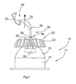
- the pull-off aid element 30 is pivoted into a pull-off position (see FIG. 3), in which the plug element 24 can be pulled out of the housing 12 or the heat sink 20 in the withdrawal direction (arrow 32).
- the trigger member 30 is embraced at its transverse web portion 42 on both sides of the longitudinal web portion 36 with one finger in order to apply a pulling force on the trigger member 30 as in a corkscrew.
Landscapes
- Engineering & Computer Science (AREA)
- General Engineering & Computer Science (AREA)
- Mechanical Engineering (AREA)
- Non-Portable Lighting Devices Or Systems Thereof (AREA)
- Arrangement Of Elements, Cooling, Sealing, Or The Like Of Lighting Devices (AREA)
- Fastening Of Light Sources Or Lamp Holders (AREA)
- Body Structure For Vehicles (AREA)
- Lighting Device Outwards From Vehicle And Optical Signal (AREA)
Description
- Die Erfindung betrifft eine Leuchte für ein Fahrzeug und insbesondere eine Leuchte für den Innenraum eines Fahrzeuges, bei der es sich insbesondere um die Leseleuchte für ein Flugzeug handelt.
- Fahrzeugleuchten weisen im Allgemeinen ein Gehäuse auf, in dem ein Leuchtmittel, beispielsweise eine Glühlampe oder ein oder mehrere LEDS angeordnet sind. Zur elektrischen Kontaktierung des Leuchtmittels ist ein Steckerelement vorgesehen, an dem sich zumeist ein elektrisches Kabel befindet.
- Ein herausziehbares Steckerelement ist aus BE 1011148-A bekannt.
- Um ein unbeabsichtigte Ablösen des Steckerelements zu vermeiden, ist dieses lediglich nach -Überwinden einer bestimmten Mindestkraft in das Gehäuse einsteckbar bzw. aus diesem herausziehbar. Für das Anschließen bzw. das Entfernen des Steckerelements sollte dieses daher mit einem bequem manuell erfassbaren Anfassende versehen sein, über das die erforderlichen Andrück- und Abzugskräfte manuell aufgebracht - werden können. Ein derartig ausgebildetes Steckerelement benötigt jedoch einen gewissen Platzbedarf und steht im Regelfall vom Gehäuse ab, was je nach Einbausituation sowie den zumeist beengten Platzverhältnissen in einem Fahrzeug problematisch ist.
- Eine Aufgabe der Erfindung ist daher, eine Leuchte für ein Fahrzeug und insbesondere eine Leseleuchte für ein Flugzeug zu schaffen, die über ein bequem handhabbares und dennoch platzsparendes Steckerelement verfügt.
- Zur Lösung dieser Aufgabe wird mit der Erfindung eine Leuchte für ein Fahrzeug und insbesondere eine Leseleuchte für ein Flugzeug vorgeschlagen, die versehen ist mit
- einem Gehäuse,
- einem in dem Gehäuse angeordneten Leuchtmittel und
- einem Steckerelement zur elektrischen Kontaktierung des Leuchtmittels und
- einem Abzugshilfeelement zum Abziehen des Steckerelements von dem Gehäuse in einer Abzugsrichtung,
- wobei das Abzugshilfeelement ein erstes Ende, das um eine quer zur Abzugsrichtung verlaufende Schwenkachse schwenkbar an dem Steckerelement angeordnet ist, und ein zweites Ende aufweist, das zum manuellen Erfassen und Ziehen an dem Abzugshilfeelement ausgebildet ist, und
- wobei das Abzugshilfeelement zwischen einer Parkposition, in der es an dem Gehäuse anliegt, und einer Abzugsposition schwenkbar ist, in der es zum Abziehen des Steckerelements von dem Gehäuse absteht.
- Die erfindungsgemäße Leuchte verfügt über ein Abzugshilfeelement, mit dem sich das Steckerelement von dem Gehäuse in einer Abzugsrichtung abziehen lässt. Das Abzugshilfeelement ist quer zur Abzugsrichtung schwenkbar an dem Steckerelement angeordnet. An einem zweiten Ende ist das Abzugshilfeelement zur manuellen Erfassung und zum manuellen Ziehen ausgebildet, was beispielsweise in Form einer Verbreiterung des zweiten Endes oder in Form einer Öffnung realisiert ist, in die hinein man mit einem oder mehreren Fingern einer Hand fassen kann. Das Abzugshilfeelement ist zwischen einer Parkposition und einer Abzugsposition schwenkbar. In der Parkposition liegt das Abzugshilfeelement an dem Gehäuse an, während es in der Abzugsposition von dem Gehäuse absteht.
- Durch die schwenkbare Lagerung des Abzugshilfeelements ist es möglich, dieses platzsparend am Gehäuse unterzubringen, wenn das Steckerelement nicht abgezogen werden soll. Zum Abziehen des Steckerelements, wie dies beispielsweise bei der Demontage bzw. dem Auswechseln des Leuchtmittels erforderlich sein kann, wird das Abzugshilfeelement in seine Abzugsposition verschwenkt, in der es an seinem freien Ende einfach manuell erfassbar ist, um auf das Abzugshilfeelement die zum Abziehen des Steckerelements erforderlichen Kräfte aufzubringen. Damit ist eine Anordnung geschaffen, die einerseits platzsparend ist und andererseits es ermöglicht, die erforderlichen Abzugskräfte auf das Steckerelement aufbringen zu können.
- In vorteilhafter Weiterbildung der Erfindung ist vorgesehen, dass ein Anschlusskabel für das Leuchtmittel, das zum Steckerelement führt, an dem Abzugshilfeorgan geführt ist. Damit wird also das Abzugshilfeelement in zweifacher Weise genutzt, nämlich auch zur Führung des Anschlusskabels, was dessen saubere und ordnungsgemäße Verlegung ermöglicht.
- In vorteilhafter Weiterbildung der Erfindung ist ferner vorgesehen, dass das Abzugshilfeelement in seiner Parkposition gegen unbeabsichtigte Bewegungen an dem Gehäuse gesichert ist. Dies kann beispielsweise durch zusätzliche Haltemittel aber auch durch eine Verrastung des Abzugshilfeelements in der Parkposition erfolgen. Diese Verrastung geschieht beispielsweise an dem schwenkbar gelagerten Ende des Abzugshilfeelements oder aber an dessen anderen (Anfass-) Ende, das zu diesem Zweck beispielsweise hinter einen Rastvorsprung oder in eine Rastvertiefung am Gehäuse einrastet:
- In zunehmendem Maße wird insbesondere für die Beleuchtung des Innenraums von Flugzeugen und vorzugsweise als Leseleuchten LEDs eingesetzt. Die während des Betriebs derartiger LEDs erzeugte Wärme muss abgeführt werden, wozu das Gehäuse einen Kühlkörper aufweist. Der Kühlkörper verfügt über mehrere Kühlrippen, die beispielsweise parallel oder sternförmig angeordnet sind. Es bietet sich bei einer derartigen Konstruktion an, dass das Abzugshilfeelement zur Sicherung in seiner Parkposition zumindest eine der Kühlrippen umgreift. In seiner Parkposition verläuft also das Abzugshilfeelement längs des Kühlkörpers und folgt dessen Formgebung, um dann an seinem zweiten Ende hinter mindestens eine freiliegende Kante oder ein anderweitig ausgebildetes Ende einer Kühlrippe zu greifen.
- Das Steckerelement befindet sich vorzugsweise in einer Aufnahmevertiefung des Gehäuses und ist in diesem gegen ein unbeabsichtigtes Ablösen und feuchtigkeitsdicht gelagert. Ist das Gehäuse an seinem mit dem Steckerelement versehenen Ende nach Art eines Doms ausgebildet, so ist es zweckmäßig, die Aufnahmevertiefung im Bereich des Scheitelpunktes des Domes anzuordnen. Bei einem derartigen Gehäuse befindet sich der vorzugsweise mit sternförmig verlaufenden Kühlrippen versehene Kühlkörper auf dem domartigen Ende des Gehäuses, auf das er aufgesetzt ist.
- Eine einfache Konstruktion des Abzugshilfeelements ist dadurch möglich, dass dieses einen Längsstegabschnitt aufweist, dessen eines Ende schwenkbar am Steckerelement gelagert ist und an dessen gegenüberliegendem anderen Ende sich ein Querstegabschnitt befindet, der quer zum Längsstegabschnitt verläuft. Dadurch entsteht eine im wesentlichen T-förmige Struktur, die sich leicht zwecks Abziehens des Steckerelements mit beispielsweise dem Zeige- und dem Mittelfinger einer Hand erfassen lässt, die um die beiden seitlich vom Längsstegabschnitt abstehenden Enden des Querstegabschnitts greifen, um in Richtung des Längsstegabschnitts Zugkräfte auf das Abzugshilfeelement ausüben zu können.
- Vorzugsweise ist der Längsstegabschnitt des Abzugshilfeelements an die äußere Kontur des Gehäuses im Bereich des Steckerelements angepasst Damit legt sich das Abzugshilfeelements in seiner Parkposition dicht an das Gehäuse an. Beispielsweise ist der Längsstegabschnitt bogenförmig ausgebildet, da das Gehäuse bzw. die an das Gehäuse angrenzende Kontur im Bereich des Steckerelements bogenförmig verläuft.
- Das Abzugshilfeelement ist zweckmäßigerweise mit einer Gitterstruktur versehen, die einzelne Verstrebungen aufweist, an den bzw. zwischen denen ein Anschlusskabel auf einfache Weise geführt werden kann. Andere Möglichkeiten der Führung eines Anschlusskabels an dem Abzugshilfeelement sind ebenfalls denkbar. Hier kommen beispielsweise separate Befestigungselemente wie Kabelbinder oder dergleichen in Frage. Vorstehende Haken, an denen das Anschlusskabel einhakbar ist, sind ebenfalls möglich.
- Die Erfindung wird nachfolgend anhand der Zeichnungen näher erläutert: Im einzeinen zeigen:
- Fig. 1
- eine Seitenansicht einer Leseleuchte für einen Flugzeugsitzplatz mit anliegenden Abzugshilfeelementen,
- Fig. 2
- eine Draufsicht auf die Leseleuchte gemäss Figur 1,
- Fig.
- eine Seitenansicht der Leseleuchte mit abstehenden Abzugshilfeelement und
- Fig. 4 und Fig. 5
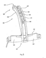
- perspektivische Darstellung des Abzugshilfeelements zur Verdeutlichurig von dessen Ausgestaltung und Konstruktion.
- Die erfindungsgemäße Fahrzeugleuchte wird nachfolgend anhand einer beispielhaften Ausgestaltung als Fahrzeuginnenraumleuchte und hier insbesondere in ihrer Verwendung als Leseleuchte für einen Flugzeug-Sitzplatz beschrieben.
- Die. Erfindung ist selbstverständlich auf die Verwendung im Innenraum eines Flugzeuges nicht beschränkt.
- Gemäss Fign. 1 bis 3 weist die (Lese-) Leuchte 10 ein Gehäuse 12 auf, das mit einem zylindrischen Gehäuseteil 14 und einem kuppel- bzw. domartigen Gehäuseteil 16 versehen ist. Andere Gehäuseformen sind ebenfalls möglich.
- In dem Gehäuse 12 befindet sich ein oder mehrere LEDs 17 als Leuchtmittel, die thermisch mit einem Kühlkörper 20 gekoppelt sind, welcher sternförmig sich erstreckende Kühlrippen 22 aufweist und auf den domartigen Gehäuseteil 16 aufgesetzt ist.
- Zur elektrischen Kontaktierung der LEDs dient ein Steckerelement 24, das in einer Aufnahmevertiefung 26 des Kühlkörpers 20 bzw. des Gehäuses 12 angeordnet ist.
- Mit dem Steckerelement 24 um eine Schwenkachse 28 schwenkbar verbunden ist ein Abzugshilfeelement 30, mit dessen Hilfe sich das Steckerelement 24 in der durch den Pfeil 32 (siehe Fig. 3) angedeuteten Abzugsrichtung aus dem Kühlkörper 20 bzw. dem Gehäuse 12 abziehen und in diese einsetzen lässt.
- Die Schwenkachse 28 ist zum Beispiel als Hohlniete oder Bolzen ausgeführt, um den das Abzugshilfeelement drehbar ist und der an dem Steckerelement 24 gelagert ist. Eine andere Art der gelenkigen Verbindung von Abzugshilfeelements 30 und Steckerelement 24 als über eine Schwenkachse, zum Beispiel durch einen Filmscharnier, ist möglich. In sämtlichen Fällen gilt, dass die Gelenkachse quer zur Abzugsrichtung (Pfeil 32) verläuft. An das Abzugshilfeelement 30 ist ferner das elektrische Anschlusskabel 33 für die LEDs 18 geführt.
- Fig. 1 zeigt die Einbausituation der Leseleuchte 10 mit Struktur- bzw. Verkleidungselementen 34,35 z.B. des Fahr- bzw. Flugzeuges. Das Abzugshilfeelement 30 befindet sich in seiner abgeklappten (Park-) Position, in der von außen an dem Kühlkörper 20 anliegt und somit die Einbauhöhe der Leseleuchte 10 nicht beeinträchtigt.
- In der Parkposition ist das Abzugshilfeelement 30 an dem Kühlkörper 20 gesichert gehalten. Das Abzugshilfeelement 30 weist einen der Kontar des Kühlkörpers 20 angepassten gebogenen Längsstegabschnitt 36 mit Gitterstruktur auf, dessen eines Ende 38 schwenkbar an dem Steckerelement 24 gelagert ist. An dem gegenüberliegenden Ende 40 des Längsstegabschnitts 36 befindet sich ein Querstegabschnitt 42, der beidseitig vom Längsstegabschnitt 36 absteht. Der Querstegabschnitt 42 weist ebenfalls eine Gitterstruktur auf und greift in der Parkposition des Abzugshilfeelements 30 unter die gegenüber dem Gehäuse 12 leicht vorstehenden Enden einiger Kühlrippen 22 (Hinterschnitt, siehe auch Fig. 2).
- Zum Abziehen des Steckerelements 24 wird das Abzugshilfeelement 30 in eine Abzugsposition verschwenkt (siehe Fig. 3), in der das Steckerelement 24 in Abzugsrichtung (Pfeil 32) aus dem Gehäuse 12 bzw. dem Kühlkörper 20 herausgezogen werden kann. Hierbei wird das Abzugshilfeelement 30 an seinem Querstegabschnitt 42 beidseitig des Längsstegabschnitts 36 mit jeweils einem Finger umgriffen, um auf das Abzugshilfeelement 30 wie bei einem Korkenzieher eine Zugkraft aufbringen zu können.
- In den Fign. 4 und 5 sind zwei perspektivische Darstellungen des Abzugshilfeelements 30 wiedergeben. Zu erkennen ist die mit Streben 44 versehene Gitterstruktur durch die hindurch und aus der heraus das Anschlusskabel 33 geführt ist. Die Verstrebungen verleihen dem Abzugshilfeelement 30 eine ausreichende Stabilität bei leichtgewichtiger Ausführung (Material z.B. ggf. faserverstärkter Kunststoff) sowie eine ausreichende Flexibilität, um das Abzugshilfeelement 30 durch Umgreifen der Enden einiger Kühlrippen 22 an dem Kühlkörper 20 in der Parkposition verrasten sowie diese Verrastung durch Lösen dieser Umgreifung wieder aufheben zu können.
Claims (12)
- Leuchte für ein Fahrzeug, insbesondere Leseleuchte für ein Flugzeug, mit- einem Gehäuse (12),- einem in dem Gehäuse (12) angeordneten Leuchtmittel (18) und- einem Steckerelement (24) zur elektrischen Kontaktierung des Leuchtmittels (18)- ein Abzugshilfeelement (30) zum Abziehen des Steckerelements (24) von dem Gehäuse (12) in einer Abzugsrichtung (32)- dadurch gekennzeichnet daß das Abzugshilfeelement (30) ein erstes Ende (38), das um eine quer zur Abzugsrichtung (32) verlaufende Schwenkachse (28) an dem Steckerelement (24) angeordnet ist, und ein zweites Ende (40) aufweist, das zum manuellen Erfassen und Ziehen an dem Abzugshilfeelement (30) ausgebildet ist, und- das Abzugshilfeelement (30) zwischen einer Parkposition, in der es an dem Gehäuse (12) anliegt, und einer Abzugsposition zum Abziehen des Steckerelements (24) von dem Gehäuse (12) schwenkbar ist, in der es von dem Gehäuse (12) absteht.
- Leuchte für ein Fahrzeug nach Anspruch 1, gekennzeichnet durch, ein Anschlusskabel (33) für das Leuchtmittel (18), wobei das Anschlusskabel (33) an dem Abzugshilfeelement (30) geführt ist
- Leuchte für ein Fahrzeug nach Anspruch 1 oder 2, gekennzeichnet durch, dass das Abzugshilfeelement (30) in seiner Parkposition an dem Gehäuse (12) gegen unbeabsichtigte Bewegungen gesichert ist.
- Leuchte für ein Fahrzeug nach einem der Ansprüche 1 bis 3, dadurch gekennzeichnet, dass das Gehäuse (12) eine Aufnahmevertiefung (26) für das Steckerelement (24) aufweist.
- Leuchte für ein Fahrzeug nach einem der Ansprüche 1 bis 4, dadurch gekennzeichnet, dass das Gehäuse (12) einen mit Kühlrippen (22) versehenen Kühlkörper (20) aufweist.
- Leuchte für ein Fahrzeug nach einem der Ansprüche 4 und 5, dadurch gekennzeichnet, dass das Abzugshilfeelement (30) in der Parkposition zumindest eine der Kühlrippen (22) umgreift.
- Leuchte für ein Fahrzeug nach einem der Ansprüche 1 bis 6, dadurch gekennzeichnet, dass das Gehäuse (12) ein nach Art eines Doms mit einem Scheitelpunkt ausgebildetes eines Ende aufweist und dass das Steckerelement (24) und, sofern vorhanden, dessen Aufnahmevertiefung (26) im Bereich des Scheitelpunkte angeordnet ist.
- Leuchte für ein Fahrzeug, nach Anspruch 6 und 7, dadurch gekennzeichnet, dass der Kühlkörper (20) an dem domartigen Ende des Gehäuses (12) angeordnet ist.
- Leuchte für ein Fahrzeug nach einem der Ansprüche 1 bis 8, dadurch gekennzeichnet, dass das Abzugshilfeelement (30) einen mit dem ersten Ende (38) versehenen Längsstegabschnitt (36) und einen das zweite Ende (40) bildenden Querstegabschnitt (42) aufweist, der quer zum Längsstegabschnitt (36) verläuft.
- Leuchte für ein Fahrzeug nach Anspruch 9, dadurch gekennzeichnet, dass der Längsstegabschnitt (36) des Abzugshilfeelementes (30) bogenförmig ausgebildet ist.
- Leuchte für ein Fahrzeug nach Anspruch 9 oder 10, dadurch gekennzeichnet, dass der Längssteg- und der Querstegabschnitt (36,42) jeweils eine Gitterstruktur mit Streben (44) aufweist, zwischen und/oder an denen ein Anschlusskabel (33) für das Leuchtmittel (18) geführt ist.
- Leuchte für ein Fahrzeug nach einem der Ansprüche 1 bis 11, dadurch gekennzeichnet, dass das Leuchtmittel (18) mindestens eine LED aufweist.
Priority Applications (4)
| Application Number | Priority Date | Filing Date | Title |
|---|---|---|---|
| ES02010557T ES2259351T3 (es) | 2002-05-10 | 2002-05-10 | Lampara para un vehiculo, en especial lampara de lectura para un avion. |
| DE50206462T DE50206462D1 (de) | 2002-05-10 | 2002-05-10 | Leuchte für ein Fahrzeug, insbesondere Leseleuchte für ein Flugzeug |
| AT02010557T ATE323624T1 (de) | 2002-05-10 | 2002-05-10 | Leuchte für ein fahrzeug, insbesondere leseleuchte für ein flugzeug |
| EP02010557A EP1361113B1 (de) | 2002-05-10 | 2002-05-10 | Leuchte für ein Fahrzeug, insbesondere Leseleuchte für ein Flugzeug |
Applications Claiming Priority (1)
| Application Number | Priority Date | Filing Date | Title |
|---|---|---|---|
| EP02010557A EP1361113B1 (de) | 2002-05-10 | 2002-05-10 | Leuchte für ein Fahrzeug, insbesondere Leseleuchte für ein Flugzeug |
Publications (2)
| Publication Number | Publication Date |
|---|---|
| EP1361113A1 EP1361113A1 (de) | 2003-11-12 |
| EP1361113B1 true EP1361113B1 (de) | 2006-04-19 |
Family
ID=29225641
Family Applications (1)
| Application Number | Title | Priority Date | Filing Date |
|---|---|---|---|
| EP02010557A Expired - Lifetime EP1361113B1 (de) | 2002-05-10 | 2002-05-10 | Leuchte für ein Fahrzeug, insbesondere Leseleuchte für ein Flugzeug |
Country Status (4)
| Country | Link |
|---|---|
| EP (1) | EP1361113B1 (de) |
| AT (1) | ATE323624T1 (de) |
| DE (1) | DE50206462D1 (de) |
| ES (1) | ES2259351T3 (de) |
Family Cites Families (3)
| Publication number | Priority date | Publication date | Assignee | Title |
|---|---|---|---|---|
| US1754658A (en) * | 1920-11-03 | 1930-04-15 | Nicholas Power Company Inc | Lamp for projecting apparatus |
| DE8903302U1 (de) * | 1989-03-16 | 1989-05-03 | Patent-Treuhand-Gesellschaft für elektrische Glühlampen mbH, 8000 München | Leuchte |
| BE1011148A6 (fr) * | 1997-05-07 | 1999-05-04 | Financ Applic Elec | Luminaire d'eclairage. |
-
2002
- 2002-05-10 ES ES02010557T patent/ES2259351T3/es not_active Expired - Lifetime
- 2002-05-10 AT AT02010557T patent/ATE323624T1/de not_active IP Right Cessation
- 2002-05-10 DE DE50206462T patent/DE50206462D1/de not_active Expired - Lifetime
- 2002-05-10 EP EP02010557A patent/EP1361113B1/de not_active Expired - Lifetime
Also Published As
| Publication number | Publication date |
|---|---|
| ES2259351T3 (es) | 2006-10-01 |
| DE50206462D1 (de) | 2006-05-24 |
| EP1361113A1 (de) | 2003-11-12 |
| ATE323624T1 (de) | 2006-05-15 |
Similar Documents
| Publication | Publication Date | Title |
|---|---|---|
| DE3813941C2 (de) | Anschlußverbindungsstück für ein geripptes Rohr | |
| DE2709604C2 (de) | ||
| DE102014118726B4 (de) | Kopplungsanordnung mit einer Fließbohrschraube | |
| DE20015529U1 (de) | Abhängelement | |
| DE202004002321U1 (de) | Positioniervorrichtung für eine Mehrsegment-Gleitschieneneinrichtung für Schubladen | |
| DE10322948A1 (de) | Kabelbinder für einen Kabelbaumabzweig | |
| DE3726200A1 (de) | Aufsatzteil, insbesondere zum halten von ski, surfbrettern oder dergleichen, fuer eine traegerstange einer aussen an einem kraftfahrzeug anzubringenden traegerkonstruktion | |
| DE102005021618B4 (de) | Fahrzeuginnenbeleuchtungslampe | |
| EP0779397A1 (de) | Abdeckanordnung | |
| DE3709335C2 (de) | ||
| EP0285699B1 (de) | Zange zum Verschieben von flexiblem Strangmaterial | |
| EP2183736B1 (de) | Kennzeichnungsvorrichtung für elektrische leitungen | |
| DE202013101929U1 (de) | Zugentlastungsgehäuse | |
| DE102020125985A1 (de) | Türdrückeraufsatz | |
| DE10220807B4 (de) | Leuchte für ein Fahrzeug, insbesondere Leseleuchte für ein Flugzeug | |
| EP1361113A1 (de) | Leuchte für ein Fahrzeug, insbesondere Leseleuchte für ein Flugzeug | |
| DE10236077B4 (de) | Befestigungssystem für Zubehörteile | |
| DE102019112612B3 (de) | Halterahmen und Steckverbinder mit einem derartigen Halterahmen | |
| EP1628046B1 (de) | Schaltvorrichtung für ein Kraftfahrzeuggetriebe | |
| EP2263292B1 (de) | Zugentlastungsvorrichtung | |
| DE69412339T2 (de) | Angelenkte Rohrschelle | |
| EP3836305B1 (de) | Anschlusseinrichtung für einen schirmleiter einer elektrischen leitung | |
| DE102014013658A1 (de) | Montagesystem, Befestigungseinrichtung und Verfahren zur Befestigung einer Leuchte und Leuchte mit einer Befestigungseinrichtung | |
| DE102013014338B4 (de) | Einsatz zum Sichern von Kabeln, Seilzügen und Leitungen an Fahrradrahmen | |
| DE102017127282A1 (de) | Leuchte mit verschiebbarem Klemmanschluss |
Legal Events
| Date | Code | Title | Description |
|---|---|---|---|
| PUAI | Public reference made under article 153(3) epc to a published international application that has entered the european phase |
Free format text: ORIGINAL CODE: 0009012 |
|
| AK | Designated contracting states |
Kind code of ref document: A1 Designated state(s): AT BE CH CY DE DK ES FI FR GB GR IE IT LI LU MC NL PT SE TR |
|
| AX | Request for extension of the european patent |
Extension state: AL LT LV MK RO SI |
|
| 17P | Request for examination filed |
Effective date: 20031206 |
|
| AKX | Designation fees paid |
Designated state(s): AT BE CH CY DE DK ES FI FR GB GR IE IT LI LU MC NL PT SE TR |
|
| GRAP | Despatch of communication of intention to grant a patent |
Free format text: ORIGINAL CODE: EPIDOSNIGR1 |
|
| RAP1 | Party data changed (applicant data changed or rights of an application transferred) |
Owner name: GOODRICH LIGHTING SYSTEMS GMBH |
|
| GRAS | Grant fee paid |
Free format text: ORIGINAL CODE: EPIDOSNIGR3 |
|
| GRAA | (expected) grant |
Free format text: ORIGINAL CODE: 0009210 |
|
| AK | Designated contracting states |
Kind code of ref document: B1 Designated state(s): AT BE CH CY DE DK ES FI FR GB GR IE IT LI LU MC NL PT SE TR |
|
| PG25 | Lapsed in a contracting state [announced via postgrant information from national office to epo] |
Ref country code: IE Free format text: LAPSE BECAUSE OF FAILURE TO SUBMIT A TRANSLATION OF THE DESCRIPTION OR TO PAY THE FEE WITHIN THE PRESCRIBED TIME-LIMIT Effective date: 20060419 Ref country code: FI Free format text: LAPSE BECAUSE OF FAILURE TO SUBMIT A TRANSLATION OF THE DESCRIPTION OR TO PAY THE FEE WITHIN THE PRESCRIBED TIME-LIMIT Effective date: 20060419 |
|
| REG | Reference to a national code |
Ref country code: GB Ref legal event code: FG4D Free format text: NOT ENGLISH |
|
| REG | Reference to a national code |
Ref country code: CH Ref legal event code: NV Representative=s name: HEPP, WENGER & RYFFEL AG |
|
| PG25 | Lapsed in a contracting state [announced via postgrant information from national office to epo] |
Ref country code: AT Free format text: LAPSE BECAUSE OF NON-PAYMENT OF DUE FEES Effective date: 20060510 |
|
| REF | Corresponds to: |
Ref document number: 50206462 Country of ref document: DE Date of ref document: 20060524 Kind code of ref document: P |
|
| PG25 | Lapsed in a contracting state [announced via postgrant information from national office to epo] |
Ref country code: MC Free format text: LAPSE BECAUSE OF NON-PAYMENT OF DUE FEES Effective date: 20060531 Ref country code: BE Free format text: LAPSE BECAUSE OF NON-PAYMENT OF DUE FEES Effective date: 20060531 |
|
| REG | Reference to a national code |
Ref country code: IE Ref legal event code: FG4D Free format text: LANGUAGE OF EP DOCUMENT: GERMAN |
|
| PG25 | Lapsed in a contracting state [announced via postgrant information from national office to epo] |
Ref country code: DK Free format text: LAPSE BECAUSE OF FAILURE TO SUBMIT A TRANSLATION OF THE DESCRIPTION OR TO PAY THE FEE WITHIN THE PRESCRIBED TIME-LIMIT Effective date: 20060719 |
|
| REG | Reference to a national code |
Ref country code: SE Ref legal event code: TRGR |
|
| GBT | Gb: translation of ep patent filed (gb section 77(6)(a)/1977) |
Effective date: 20060726 |
|
| PG25 | Lapsed in a contracting state [announced via postgrant information from national office to epo] |
Ref country code: PT Free format text: LAPSE BECAUSE OF FAILURE TO SUBMIT A TRANSLATION OF THE DESCRIPTION OR TO PAY THE FEE WITHIN THE PRESCRIBED TIME-LIMIT Effective date: 20060919 |
|
| REG | Reference to a national code |
Ref country code: ES Ref legal event code: FG2A Ref document number: 2259351 Country of ref document: ES Kind code of ref document: T3 |
|
| REG | Reference to a national code |
Ref country code: IE Ref legal event code: FD4D |
|
| ET | Fr: translation filed | ||
| PLBE | No opposition filed within time limit |
Free format text: ORIGINAL CODE: 0009261 |
|
| STAA | Information on the status of an ep patent application or granted ep patent |
Free format text: STATUS: NO OPPOSITION FILED WITHIN TIME LIMIT |
|
| 26N | No opposition filed |
Effective date: 20070122 |
|
| BERE | Be: lapsed |
Owner name: GOODRICH LIGHTING SYSTEMS G.M.B.H. Effective date: 20060531 |
|
| PG25 | Lapsed in a contracting state [announced via postgrant information from national office to epo] |
Ref country code: GR Free format text: LAPSE BECAUSE OF FAILURE TO SUBMIT A TRANSLATION OF THE DESCRIPTION OR TO PAY THE FEE WITHIN THE PRESCRIBED TIME-LIMIT Effective date: 20060720 |
|
| PG25 | Lapsed in a contracting state [announced via postgrant information from national office to epo] |
Ref country code: LU Free format text: LAPSE BECAUSE OF NON-PAYMENT OF DUE FEES Effective date: 20060510 Ref country code: TR Free format text: LAPSE BECAUSE OF FAILURE TO SUBMIT A TRANSLATION OF THE DESCRIPTION OR TO PAY THE FEE WITHIN THE PRESCRIBED TIME-LIMIT Effective date: 20060419 |
|
| PG25 | Lapsed in a contracting state [announced via postgrant information from national office to epo] |
Ref country code: CY Free format text: LAPSE BECAUSE OF FAILURE TO SUBMIT A TRANSLATION OF THE DESCRIPTION OR TO PAY THE FEE WITHIN THE PRESCRIBED TIME-LIMIT Effective date: 20060419 |
|
| PGFP | Annual fee paid to national office [announced via postgrant information from national office to epo] |
Ref country code: ES Payment date: 20100526 Year of fee payment: 9 |
|
| PGFP | Annual fee paid to national office [announced via postgrant information from national office to epo] |
Ref country code: IT Payment date: 20100525 Year of fee payment: 9 Ref country code: NL Payment date: 20100524 Year of fee payment: 9 |
|
| PGFP | Annual fee paid to national office [announced via postgrant information from national office to epo] |
Ref country code: CH Payment date: 20100525 Year of fee payment: 9 |
|
| PGFP | Annual fee paid to national office [announced via postgrant information from national office to epo] |
Ref country code: SE Payment date: 20100527 Year of fee payment: 9 |
|
| REG | Reference to a national code |
Ref country code: NL Ref legal event code: V1 Effective date: 20111201 |
|
| REG | Reference to a national code |
Ref country code: CH Ref legal event code: PL |
|
| REG | Reference to a national code |
Ref country code: SE Ref legal event code: EUG |
|
| PG25 | Lapsed in a contracting state [announced via postgrant information from national office to epo] |
Ref country code: LI Free format text: LAPSE BECAUSE OF NON-PAYMENT OF DUE FEES Effective date: 20110531 Ref country code: NL Free format text: LAPSE BECAUSE OF NON-PAYMENT OF DUE FEES Effective date: 20111201 Ref country code: CH Free format text: LAPSE BECAUSE OF NON-PAYMENT OF DUE FEES Effective date: 20110531 |
|
| PG25 | Lapsed in a contracting state [announced via postgrant information from national office to epo] |
Ref country code: IT Free format text: LAPSE BECAUSE OF NON-PAYMENT OF DUE FEES Effective date: 20110510 |
|
| REG | Reference to a national code |
Ref country code: ES Ref legal event code: FD2A Effective date: 20121116 |
|
| PG25 | Lapsed in a contracting state [announced via postgrant information from national office to epo] |
Ref country code: ES Free format text: LAPSE BECAUSE OF NON-PAYMENT OF DUE FEES Effective date: 20110511 |
|
| PG25 | Lapsed in a contracting state [announced via postgrant information from national office to epo] |
Ref country code: SE Free format text: LAPSE BECAUSE OF NON-PAYMENT OF DUE FEES Effective date: 20110511 |
|
| PGFP | Annual fee paid to national office [announced via postgrant information from national office to epo] |
Ref country code: GB Payment date: 20130508 Year of fee payment: 12 |
|
| GBPC | Gb: european patent ceased through non-payment of renewal fee |
Effective date: 20140510 |
|
| PG25 | Lapsed in a contracting state [announced via postgrant information from national office to epo] |
Ref country code: GB Free format text: LAPSE BECAUSE OF NON-PAYMENT OF DUE FEES Effective date: 20140510 |
|
| REG | Reference to a national code |
Ref country code: FR Ref legal event code: PLFP Year of fee payment: 15 |
|
| REG | Reference to a national code |
Ref country code: DE Ref legal event code: R079 Ref document number: 50206462 Country of ref document: DE Free format text: PREVIOUS MAIN CLASS: B60Q0003020000 Ipc: B60Q0003200000 |
|
| REG | Reference to a national code |
Ref country code: FR Ref legal event code: PLFP Year of fee payment: 16 |
|
| REG | Reference to a national code |
Ref country code: FR Ref legal event code: PLFP Year of fee payment: 17 |
|
| PGFP | Annual fee paid to national office [announced via postgrant information from national office to epo] |
Ref country code: DE Payment date: 20210421 Year of fee payment: 20 Ref country code: FR Payment date: 20210421 Year of fee payment: 20 |
|
| REG | Reference to a national code |
Ref country code: DE Ref legal event code: R071 Ref document number: 50206462 Country of ref document: DE |